Page 2798 of 5135
5100G±06
51±2
±
POWER STEERING POWER STEERING SYSTEM
AVENSIS REPAIR MANUAL (RM1018E)
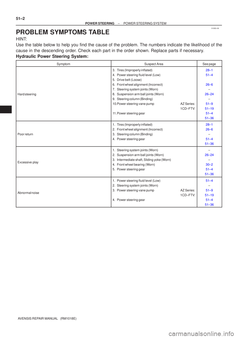
PROBLEM SYMPTOMS TABLE
HINT:
Use the table below to help you find the cause of the problem. The numbers \
indicate the likelihood of the
cause in the descending order. Check each part in the order shown. Replace parts if necessary.
Hydraulic Power Steering System:
SymptomSuspect AreaSee page
Hard steering
3. Tires (Improperly inflated)
4. Power steering fluid level (Low)
5. Drive belt (Loose)
6. Front wheel alignment (Incorrect)
7. Steering system joints (Worn)
8. Suspension arm ball joints (Worn)
9. Steering column (Binding)
10.Power steering vane pump AZ Series: 1CD±FTV:
11. Power steering gear28±1
51±4
26±6 ±
26±24 ±
51±9
51±19 51±4
51±36
Poor return
1. Tires (Improperly inflated)
2. Front wheel alignment (Incorrect)
3. Steering column (Binding)
4. Power steering gear28±1
26±6 ±
51±4
51±36
Excessive play
1. Steering system joints (Worn)
2. Suspension arm ball joints (Worn)
3. Intermediate shaft, Sliding yoke (Worn)
4. Front wheel bearing (Worn)
5. Power steering gear±
26±24 ±
30±2
51±4
51±36
Abnormal noise
1. Power steering fluid level (Low)
2. Steering system joints (Worn)
3. Power steering vane pump AZ Series: 1CD±FTV:
4. Power steering gear51±4
±
51±9
51±19 51±4
51±36
Page 2799 of 5135
±
POWER STEERING POWER STEERING SYSTEM
51±3
AVENSIS REPAIR MANUAL (RM1018E)
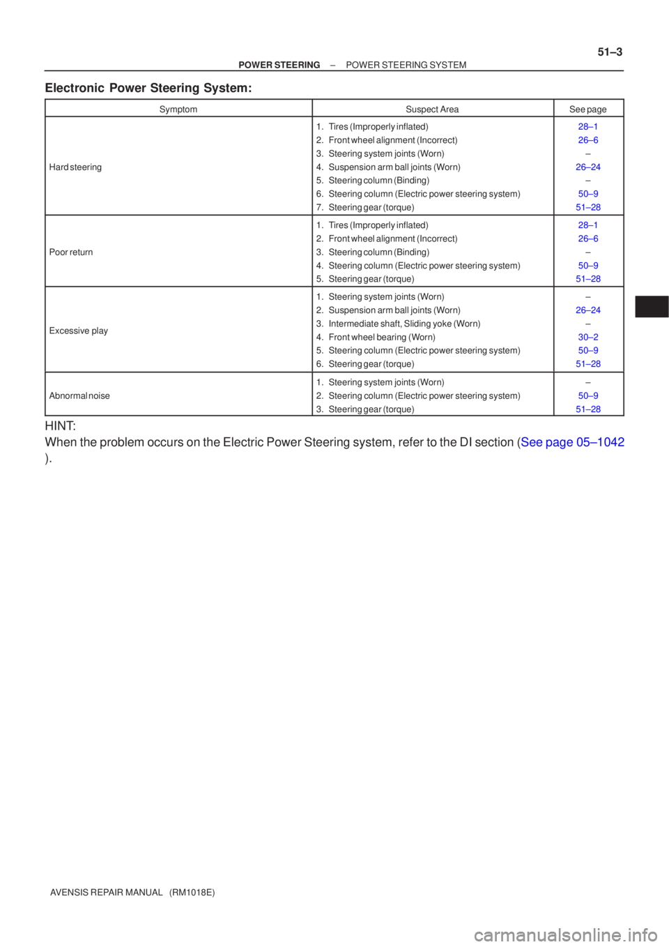
Electronic Power Steering System:
SymptomSuspect AreaSee page
Hard steering
1. Tires (Improperly inflated)
2. Front wheel alignment (Incorrect)
3. Steering system joints (Worn)
4. Suspension arm ball joints (Worn)
5. Steering column (Binding)
6. Steering column (Electric power steering system)
7. Steering gear (torque)28±1
26±6
±
26±24 ±
50±9
51±28
Poor return
1. Tires (Improperly inflated)
2. Front wheel alignment (Incorrect)
3. Steering column (Binding)
4. Steering column (Electric power steering system)
5. Steering gear (torque)28±1
26±6 ±
50±9
51±28
Excessive play
1. Steering system joints (Worn)
2. Suspension arm ball joints (Worn)
3. Intermediate shaft, Sliding yoke (Worn)
4. Front wheel bearing (Worn)
5. Steering column (Electric power steering system)
6. Steering gear (torque)±
26±24 ±
30±2
50±9
51±28
Abnormal noise
1. Steering system joints (Worn)
2. Steering column (Electric power steering system)
3. Steering gear (torque)±
50±9
51±28
HINT:
When the problem occurs on the Electric Power Steering system, refer to \
the DI section (See page 05±1042
).
Page 2820 of 5135
5000D±14
50±2
±
STEERING COLUMN STEERING SYSTEM
AVENSIS REPAIR MANUAL (RM1018E)
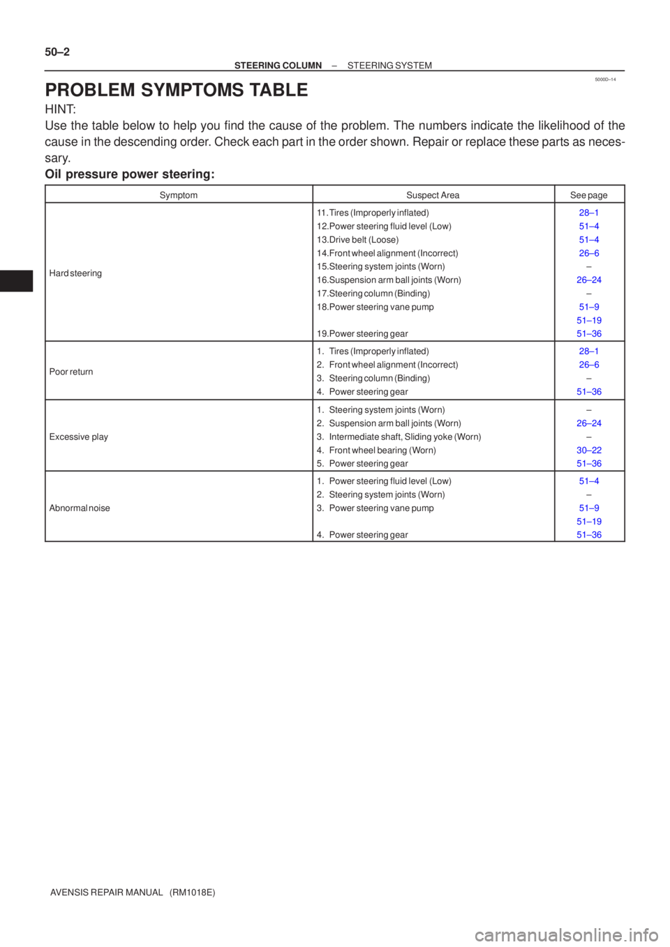
PROBLEM SYMPTOMS TABLE
HINT:
Use the table below to help you find the cause of the problem. The numbers \
indicate the likelihood of the
cause in the descending order. Check each part in the order shown. Repair or replace these parts as n\
eces-
sary.
Oil pressure power steering:
SymptomSuspect AreaSee page
Hard steering
11. Tires (Improperly inflated)
12.Power steering fluid level (Low)
13.Drive belt (Loose)
14.Front wheel alignment (Incorrect)
15.Steering system joints (Worn)
16.Suspension arm ball joints (Worn)
17.Steering column (Binding)
18.Power steering vane pump
19.Power steering gear28±1
51±4
51±4
26±6 ±
26±24 ±
51±9
51±19
51±36
Poor return
1. Tires (Improperly inflated)
2. Front wheel alignment (Incorrect)
3. Steering column (Binding)
4. Power steering gear28±1
26±6 ±
51±36
Excessive play
1. Steering system joints (Worn)
2. Suspension arm ball joints (Worn)
3. Intermediate shaft, Sliding yoke (Worn)
4. Front wheel bearing (Worn)
5. Power steering gear±
26±24 ±
30±22
51±36
Abnormal noise
1. Power steering fluid level (Low)
2. Steering system joints (Worn)
3. Power steering vane pump
4. Power steering gear51±4 ±
51±9
51±19
51±36
Page 2821 of 5135
±
STEERING COLUMN STEERING SYSTEM
50±3
AVENSIS REPAIR MANUAL (RM1018E)
Electric power steering:
SymptomSuspect AreaSee page
Hard steering
1. Tires (Improperly inflated)
2. Front wheel alignment (Incorrect)
3. Steering system joints (Worn)
4. Suspension arm ball joints (Worn)
5. Steering column (Binding)
6. Steering column (Electric power steering)28±1
26±6
±
26±24 ±
50±9
Poor return
1. Tires (Improperly inflated)
2. Front wheel alignment (Incorrect)
3. Steering column (Binding)
4. Steering column (Electric power steering)28±1
26±6 ±
50±9
Excessive play
1. Steering system joints (Worn)
2. Suspension arm ball joints (Worn)
3. Intermediate shaft, Sliding yoke (Worn)
4. Front wheel bearing (Worn)
5. Steering column (Electric power steering)±
26±24 ±
30±22 50±9
Abnormal noise1. Steering system joints (Worn)
2. Steering column (Electric power steering)±
50±9
HINT:
When the problem occurs on the Electric Power Steering system, refer to \
the DI section (See page 05±1042
).
Page 2844 of 5135
�����\b�����D30389
AZ Series:1CD±FTV:
No.1 Engine Hanger
No.2 Engine Hanger
No.1 Engine Hanger
No.2 Engine Hanger
No.1 Engine
Hanger UPR
D29969
C94595
51±38
±
POWER STEERING RACK & PINION POWER STEERING GEAR ASSY
AVENSIS REPAIR MANUAL (RM1018E)
15.SEPARATE FRONT SUSPENSION ARM SUB±ASSY LOWER NO.1 LH (See page 30±6)
16. SEPARATE FRONT SUSPENSION ARM SUB±ASSY LOWER NO.1 RH
HINT:
Perform the same procedure on the other side.
17. REMOVE HOOD SUB±ASSY
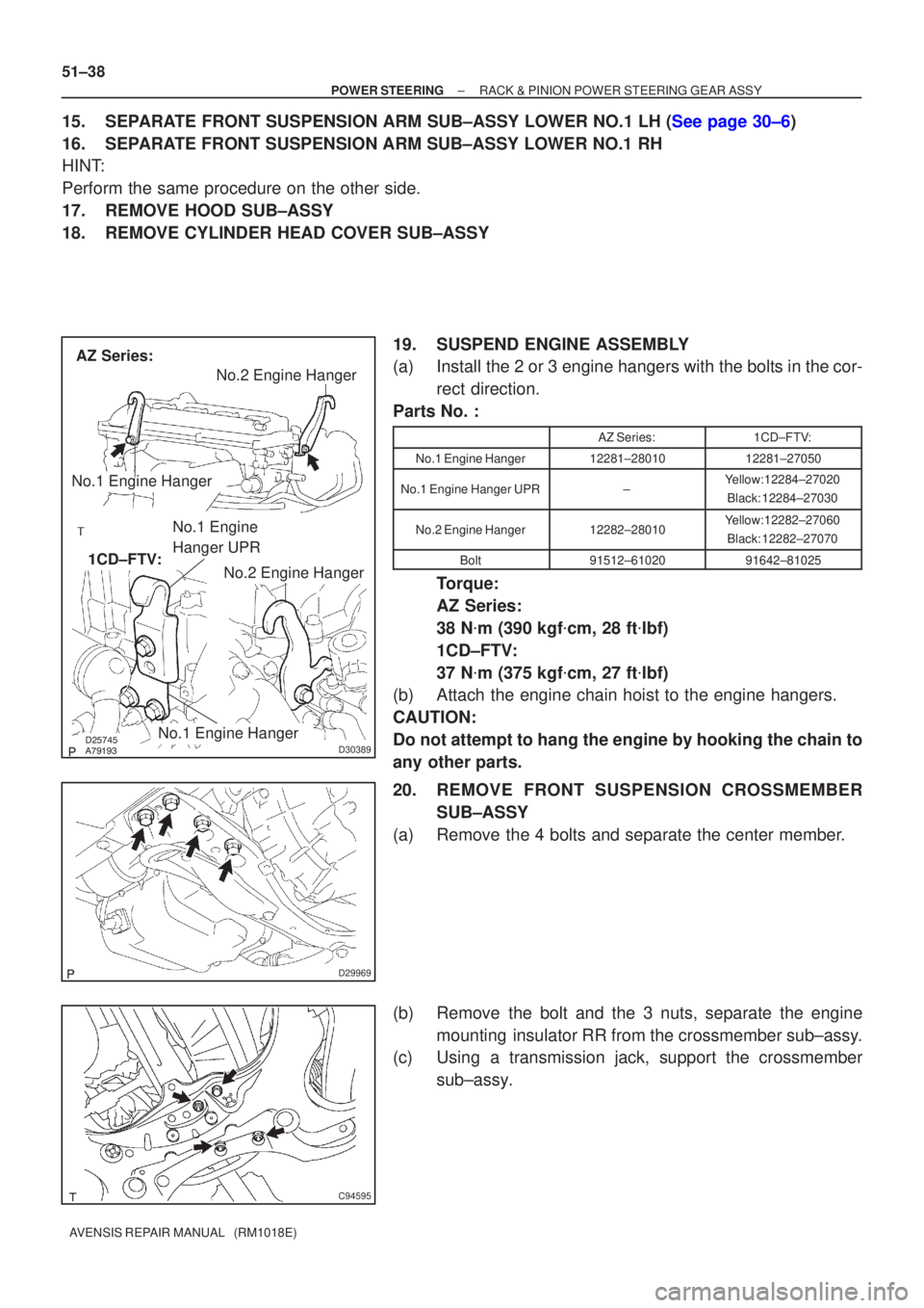
18. REMOVE CYLINDER HEAD COVER SUB±ASSY 19. SUSPEND ENGINE ASSEMBLY
(a) Install the 2 or 3 engine hangers with the bolts in the cor-rect direction.
Parts No. :
AZ Series:1CD±FTV:
No.1 Engine Hanger12281±2801012281±27050
No.1 Engine Hanger UPR±Yellow: 12284±27020
Black: 12284±27030
No.2 Engine Hanger12282±28010Yellow: 12282±27060Black: 12282±27070
Bolt91512±6102091642±81025
Torque:
AZ Series:
38 N �m (390 kgf �cm, 28 ft �lbf)
1CD±FTV:
37 N �m (375 kgf �cm, 27 ft �lbf)
(b) Attach the engine chain hoist to the engine hangers.
CAUTION:
Do not attempt to hang the engine by hooking the chain to
any other parts.
20. REMOVE FRONT SUSPENSION CROSSMEMBER
SUB±ASSY
(a) Remove the 4 bolts and separate the center member.
(b) Remove the bolt and the 3 nuts, separate the engine mounting insulator RR from the crossmember sub±assy.
(c) Using a transmission jack, support the crossmember
sub±assy.
Page 2849 of 5135
C94598
C94596
A
BB
B
LH:
C94597
A
BB
B
RH:
C94595
D29969
A
B
A
B
± POWER STEERINGRACK & PINION POWER STEERING GEAR ASSY
51±43
AVENSIS REPAIR MANUAL (RM1018E)
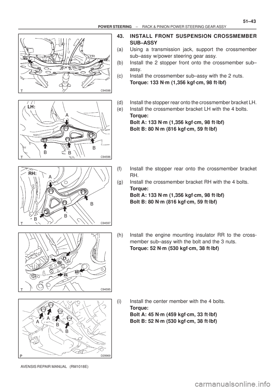
43. INSTALL FRONT SUSPENSION CROSSMEMBER
SUB±ASSY
(a) Using a transmission jack, support the crossmember
sub±assy w/power steering gear assy.
(b) Install the 2 stopper front onto the crossmember sub±
assy.
(c) Install the crossmember sub±assy with the 2 nuts.
Torque: 133 N�m (1,356 kgf�cm, 98 ft�lbf)
(d) Install the stopper rear onto the crossmember bracket LH.
(e) Install the crossmember bracket LH with the 4 bolts.
Torque:
Bolt A: 133 N�m (1,356 kgf�cm, 98 ft�lbf)
Bolt B: 80 N�m (816 kgf�cm, 59 ft�lbf)
(f) Install the stopper rear onto the crossmember bracket
RH.
(g) Install the crossmember bracket RH with the 4 bolts.
Torque:
Bolt A: 133 N�m (1,356 kgf�cm, 98 ft�lbf)
Bolt B: 80 N�m (816 kgf�cm, 59 ft�lbf)
(h) Install the engine mounting insulator RR to the cross-
member sub±assy with the bolt and the 3 nuts.
Torque: 52 N�m (530 kgf�cm, 38 ft�lbf)
(i) Install the center member with the 4 bolts.
Torque:
Bolt A: 45 N�m (459 kgf�cm, 33 ft�lbf)
Bolt B: 52 N�m (530 kgf�cm, 38 ft�lbf)
Page 2850 of 5135
D29968
RHD:
LHD:
Fulcrum Length
Fulcrum Length
SST(s)
SST(s)
D29967
RHD:
LHD:
Fulcrum LengthFulcrum
Length
SST(s)
SST(s)
51±44
±
POWER STEERING RACK & PINION POWER STEERING GEAR ASSY
AVENSIS REPAIR MANUAL (RM1018E)
44.INSTALL FRONT SUSPENSION ARM SUB±ASSY LOWER NO.1 LH (See page 30±6)
45. INSTALL FRONT SUSPENSION ARM SUB±ASSY LOWER NO.1 RH
HINT:
Perform the same procedure on the other side.
46.INSTALL FRONT STABILIZER LINK ASSY LH (See page 30±6)
47. INSTALL FRONT STABILIZER LINK ASSY RH
HINT:
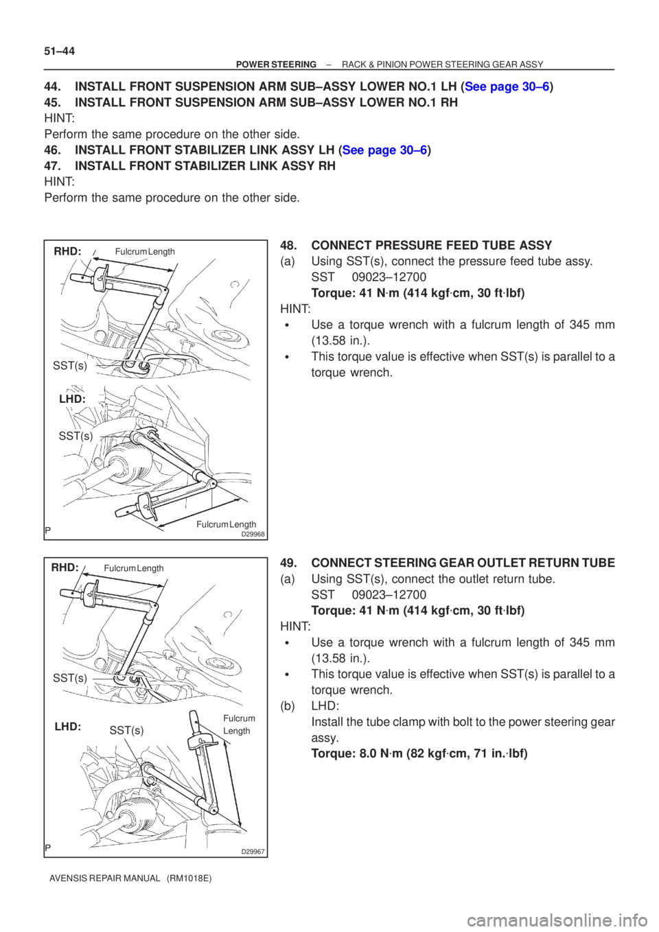
Perform the same procedure on the other side. 48. CONNECT PRESSURE FEED TUBE ASSY
(a) Using SST(s), connect the pressure feed tube assy.SST 09023±12700
Torque: 41 N �m (414 kgf �cm, 30 ft �lbf)
HINT:
�Use a torque wrench with a fulcrum length of 345 mm
(13.58 in.).
�This torque value is effective when SST(s) is parallel to a
torque wrench.
49. CONNECT STEERING GEAR OUTLET RETURN TUBE
(a) Using SST(s), connect the outlet return tube. SST 09023±12700
Torque: 41 N �m (414 kgf �cm, 30 ft �lbf)
HINT:
�Use a torque wrench with a fulcrum length of 345 mm
(13.58 in.).
�This torque value is effective when SST(s) is parallel to a
torque wrench.
(b) LHD: Install the tube clamp with bolt to the power steering gear
assy.
Torque: 8.0 N �m (82 kgf �cm, 71 in. �lbf)
Page 2852 of 5135
510DK±02
D29958
LHD:
Pressure Feed
Tube Assy8.0 (82, 71 in.�lbf)
Steering Gear Outlet
Return Tube
44.1 (450, 33)
*41 (414, 30)
Steering Intermediate Shaft Assy No.2
35 (360, 26)
Steering Intermediate Shaft
Column Hole Cover
Silencer Sheet
Clip
Steering Gear Outlet Return Tube
Pressure Feed Tube Assy Steering Column Hole
Cover Sub±assy No.1
�Cotter Pin
Rack & Pinion Power
Steering Gear Assy
Stopper Rear
80 (816, 59)
80 (816, 59)
133 (1,356, 98)
Front Stabilizer
Link Assy RH
Stopper
Front
133 (1,356, 98)
89 (908, 66)
74 (755, 55)
Front Stabilizer Link Assy LH
Stopper Rear
Crossmember
Bracket LH
80 (816, 59)
133 (1,356, 98)
80 (816, 59)
N�m (kgf�cm, ft�lbf): Specified torque � Non±reusable part
* For use with SST(s)
52 (530, 38)
133 (1,356, 98)
52 (530, 38)
Center Member
74 (755, 55)49 (500, 36)
Front Suspension
Crossmember Sub±assy
Stopper Front
49 (500, 36)
35 (360, 26)
89 (908, 66)
Engine Under Cover LH Engine Under
Cover RH
45 (459, 33)
49 (500, 36)49 (500, 36)
49 (500, 36)
44.1 (450, 33)
*41 (414, 30)
44.1 (450, 33)
*41 (414, 30)
51±34
± POWER STEERINGRACK & PINION POWER STEERING GEAR ASSY
AVENSIS REPAIR MANUAL (RM1018E)
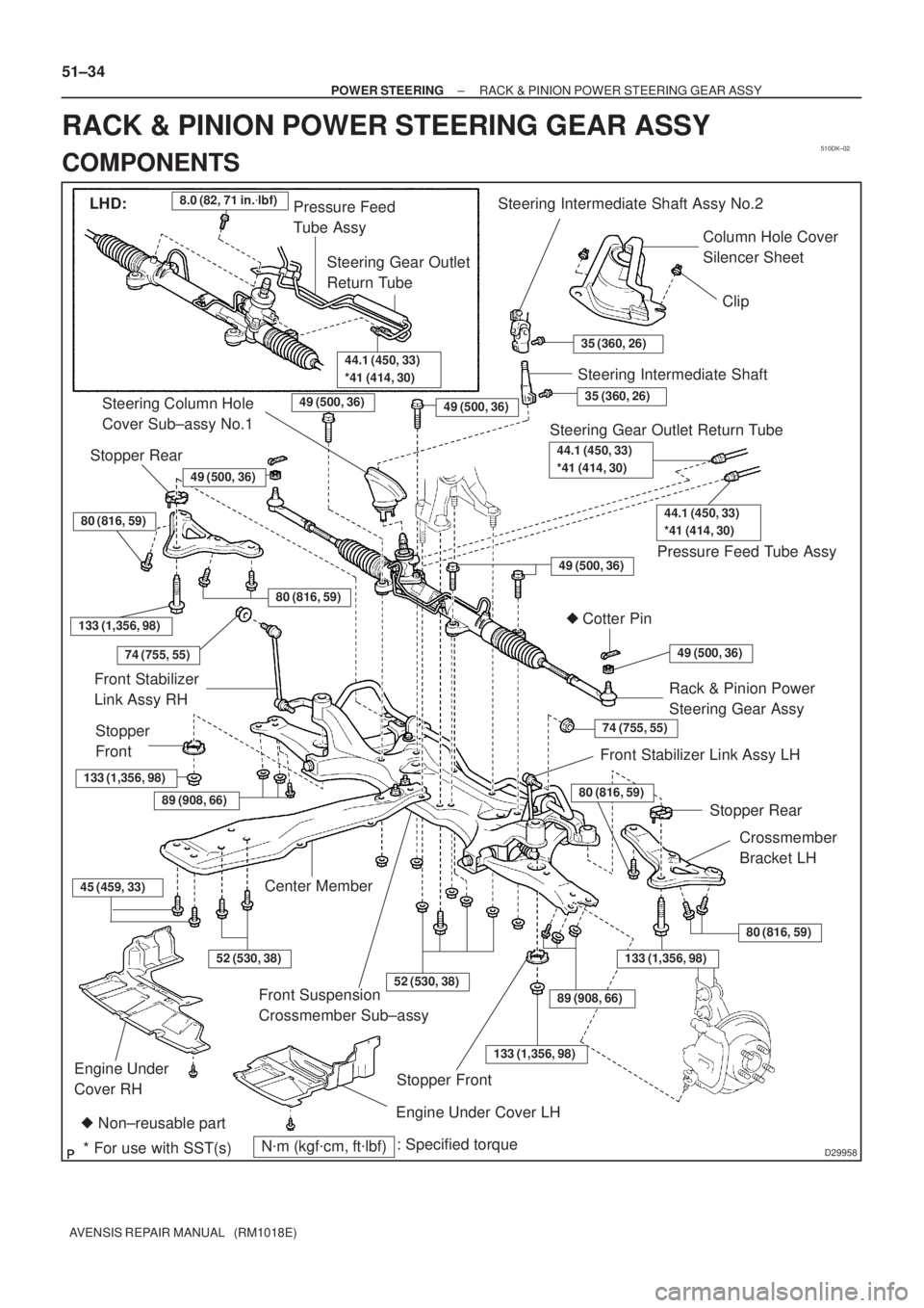
RACK & PINION POWER STEERING GEAR ASSY
COMPONENTS