Page 4709 of 5135
A93083
Cooler Bracket
(LHD Steering Position Type)
Oil Reservoir
Bracket No. 1Heater Outlet Water Hose
Heater Inlet Water Hose
Steering Intermediate
Shaft Assy No. 2
Column Hole Cover Silencer Sheet
Front Stabilizer Link Assy
Front Axle Assy
35 (360, 26)
7.0 (71, 62 in.�lbf)
74 (755, 55)
216 (2,203,159 )
89 (908, 66)
N·m (kgf·cm, ft·lbf)
: Specified torque
zNon−reusable partzFront Axle Hub Nut
Tie Rod End Sub−assy
8.0 (82, 71 in.�lbf)
8.0 (82, 71 in.�lbf)
zCotter Pin
49 (500, 36)
Front Suspension Arm
Sub−assy Lower No. 1
14−14
− ENGINE MECHANICALPARTIAL ENGINE ASSY (2AZ−FSE)
AVENSIS Supplement (RM1045E)
Page 4710 of 5135
A93082
87 (887, 64)
37 (377, 27)
52 (530, 38)
87 (887, 64)52 (530, 38)
52 (530, 38)
52 (530, 38)52 (530, 38)
52 (530, 38)
133 (1,356, 83)
80 (816, 59)
80 (816, 59)
133 (1,356, 83)
45 (459, 33)
133 (1,356, 83)
Engine Mounting Bracket No. 2 RH
Transverse Engine
Engine Mounting Insulator
Front Suspension Brace RH
Front Suspension
Brace LH
Front Drive Shaft Assy RH
Front Drive Shaft Assy LH Engine Assembly
with Transaxle
Front Suspension Crossmember
w/ Center Member
N·m (kgf·cm, ft·lbf)
: Specified torque
Vane Pump Assy
113 (1,152, 83)
87 (887, 64)
x2
− ENGINE MECHANICALPARTIAL ENGINE ASSY (2AZ−FSE)
14−15
AVENSIS Supplement (RM1045E)
Page 4732 of 5135
F40217
SSTTurn
Hold
C80293
D27403
F40148SST
− DRIVE SHAFT / PROPELLER SHAFTFRONT DRIVE SHAFT (2AZ−FSE)
30−5
AVENSIS Supplement (RM1045E)
7. SEPARATE TIE ROD END SUB−ASSY LH
(a) Remove the cotter pin and nut.
(b) Using SST, separate the tie rod end sub−assy LH from the
steering knuckle.
SST 09628−62011
8. SEPARATE FRONT SUSPENSION ARM SUB−ASSY
LOWER NO.1LH
(a) Remove the bolt and 2 nuts, and separate the front sus-
pension arm sub−assy lower No.1LH from the lower ball
joint.
9. SEPARATE FRONT AXLE ASSY LH
(a) Using a plastic hammer, separate the front drive shaft
assy LH from the axle hub.
NOTICE:
Be careful not to damage the boot and speed sensor rotor.
10. REMOVE FRONT DRIVE SHAFT ASSY LH
(a) Using SST, remove the front drive shaft assy LH.
SST 09520−01010, 09520−24010 (09520−32040)
NOTICE:
SBe careful not to damage the oil seal, boot and dust
cover.
SBe careful not to drop the drive shaft assy.
Page 4742 of 5135

C81796F45254
(A)
C83851
C83155
C80293
− DRIVE SHAFT / PROPELLER SHAFTFRONT DRIVE SHAFT (2AZ−FSE)
30−15
AVENSIS Supplement (RM1045E)
HINT:
For dimension (A), refer to the following table.
Drive shaft typeDimension (A) mm (in.)
LH546.1(21.50)�á5.0 (0.20)
RH884.0 (34.80)�á5.0 (0.20)
41. INSTALL FRONT DRIVE SHAFT ASSY LH
(a) Coat the inboard joint shaft assy LH spline with gear oil.
(b) Align the shaft splines and install the drive shaft assy LH
with a brass bar and hammer.
NOTICE:
SSet the snap ring with the opening side facing down-
wards.
SBe careful not to damage the oil seal, boot and dust
cover.
42. INSTALL FRONT DRIVE SHAFT ASSY RH (RH DRIVE
SHAFT)
(a) Coat the inboard joint shaft assy RH spline with gear oil.
(b) Align the shaft splines and install the drive shaft assy RH
with the 2 bolts.
Torque: 64 N�m (650 kgf�cm, 47 ft�lbf)
NOTICE:
Do not damage the oil seal, boot and dust cover.
43. INSTALL FRONT AXLE ASSY LH
(a) Install the drive shaft assy LH to the front axle assy LH.
NOTICE:
SBe careful not to damage the outboard joint boot.
SBe careful not to damage the speed sensor rotor.
44. INSTALL FRONT SUSPENSION ARM SUB−ASSY
LOWER NO.1LH
(a) Install the lower ball joint to the front suspension arm sub−
assy lower No.1LH with the bolt and 2 nuts.
Torque: 89 N�m (908 kgf�cm, 66 ft�lbf)
Page 5070 of 5135

A64005
A76715
– ENGINE MECHANICALPARTIAL ENGINE ASSY (1ZZ–FE/3ZZ–FE)(From
February, 2004)14–13
AVENSIS REPAIR MANUAL SUPPLEMENT
(RM1098E)
49. REMOVE FRONT AXLE HUB RH NUT
SST 09930–00010
HINT:
Perform the same procedure as above on the opposite side.
50. SEPARATE TIE ROD END SUB–ASSY LH (See Pub. No. RM1018E on page 30–6)
SST 09628–62011
51. SEPARATE TIE ROD END SUB–ASSY RH
SST 09628–62011
HINT:
Perform the same procedure as above on the opposite side.
52. SEPARATE FRONT STABILIZER LINK ASSY LH (See Pub. No. RM1018E on page 30–6)
53. SEPARATE FRONT STABILIZER LINK ASSY RH
HINT:
Perform the same procedure as above on the opposite side.
54. SEPARATE FRONT SUSPENSION ARM SUB–ASSY LOWER NO.1 LH
(See Pub. No. RM1018E on page 30–6)
55. SEPARATE FRONT SUSPENSION ARM SUB–ASSY LOWER NO.1 RH
HINT:
Perform the same procedure as above on the opposite side.
56. SEPARATE FRONT AXLE ASSY LH (See Pub. No. RM1018E on page 30–6)
57. SEPARATE FRONT AXLE ASSY RH
HINT:
Perform the same procedure as above on the opposite side.
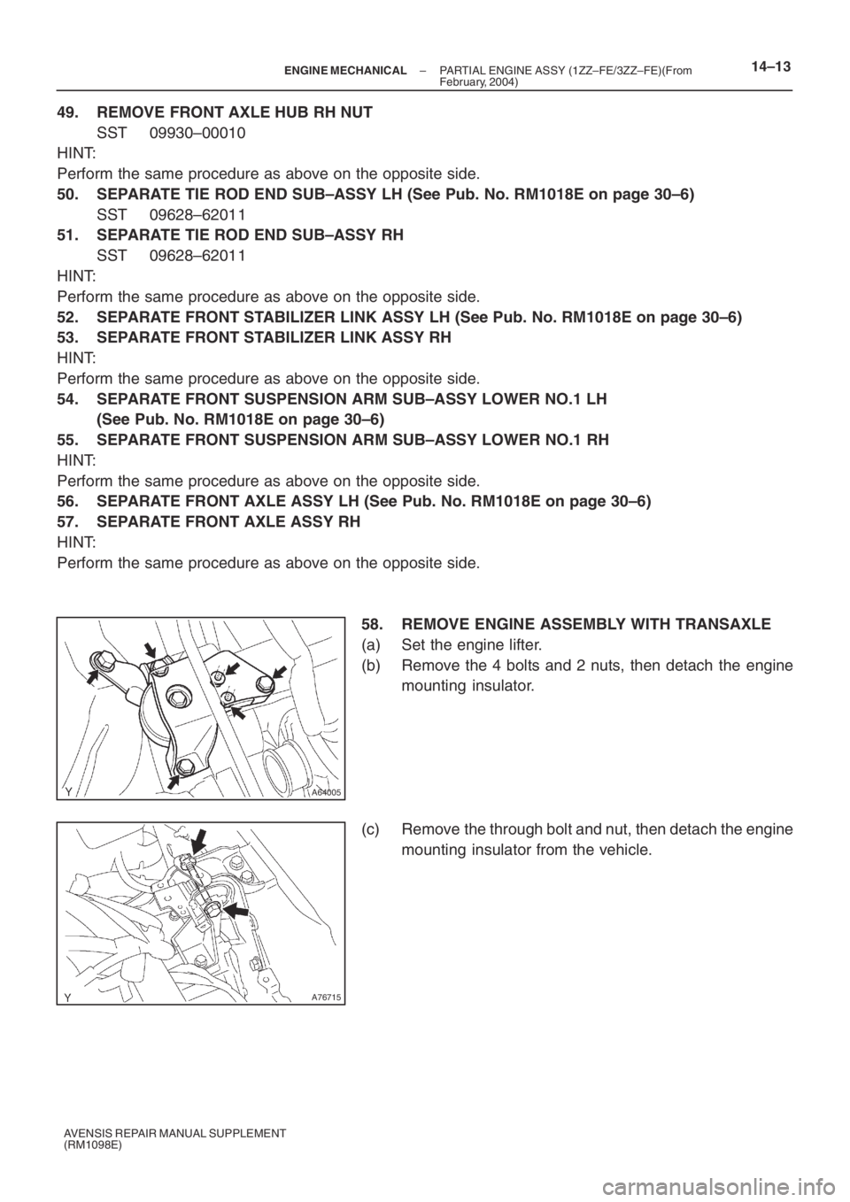
58. REMOVE ENGINE ASSEMBLY WITH TRANSAXLE
(a) Set the engine lifter.
(b) Remove the 4 bolts and 2 nuts, then detach the engine
mounting insulator.
(c) Remove the through bolt and nut, then detach the engine
mounting insulator from the vehicle.
Page 5071 of 5135
A76717
A76716
A62830Front SideRear Side
A76718
14–14– ENGINE MECHANICALPARTIAL ENGINE ASSY (1ZZ–FE/3ZZ–FE)(From
February, 2004)
AVENSIS REPAIR MANUAL SUPPLEMENT
(RM1098E)
(d) Remove the 2 bolts and 2 nuts as shown in the illustration.
(e) Remove the 8 bolts and front suspension member brace
rear RH and LH.
(f) Carefully remove the engine with transaxle from the en-
gine compartment.
(g) Install the engine hanger No. 1 (12281–15040) and bolt
(91512–B1016).
Torque: 38 N⋅m (387 kgf⋅cm, 28 ft⋅lbf)
(h) Install the engine hanger (12281–22021) and bolt
(91512–B1016).
Torque: 38 N⋅m (387 kgf⋅cm, 28 ft⋅lbf)
HINT:
Securely install the front engine hanger (12281–22021) and
rear engine hanger No. 1 (12281–15040) onto the engine as-
sembly.
(i) Attach the engine sling, then hang the engine with the
chain block.
59. REMOVE FRONT SUSPENSION CROSSMEMBER
W/CENTER MEMBER
(a) Remove the through bolt and nut, then detach the engine
mounting insulator FR from the engine mounting bracket.
Page 5072 of 5135

A76719
A62838SST
A62838SST
A76713
– ENGINE MECHANICALPARTIAL ENGINE ASSY (1ZZ–FE/3ZZ–FE)(From
February, 2004)14–15
AVENSIS REPAIR MANUAL SUPPLEMENT
(RM1098E)
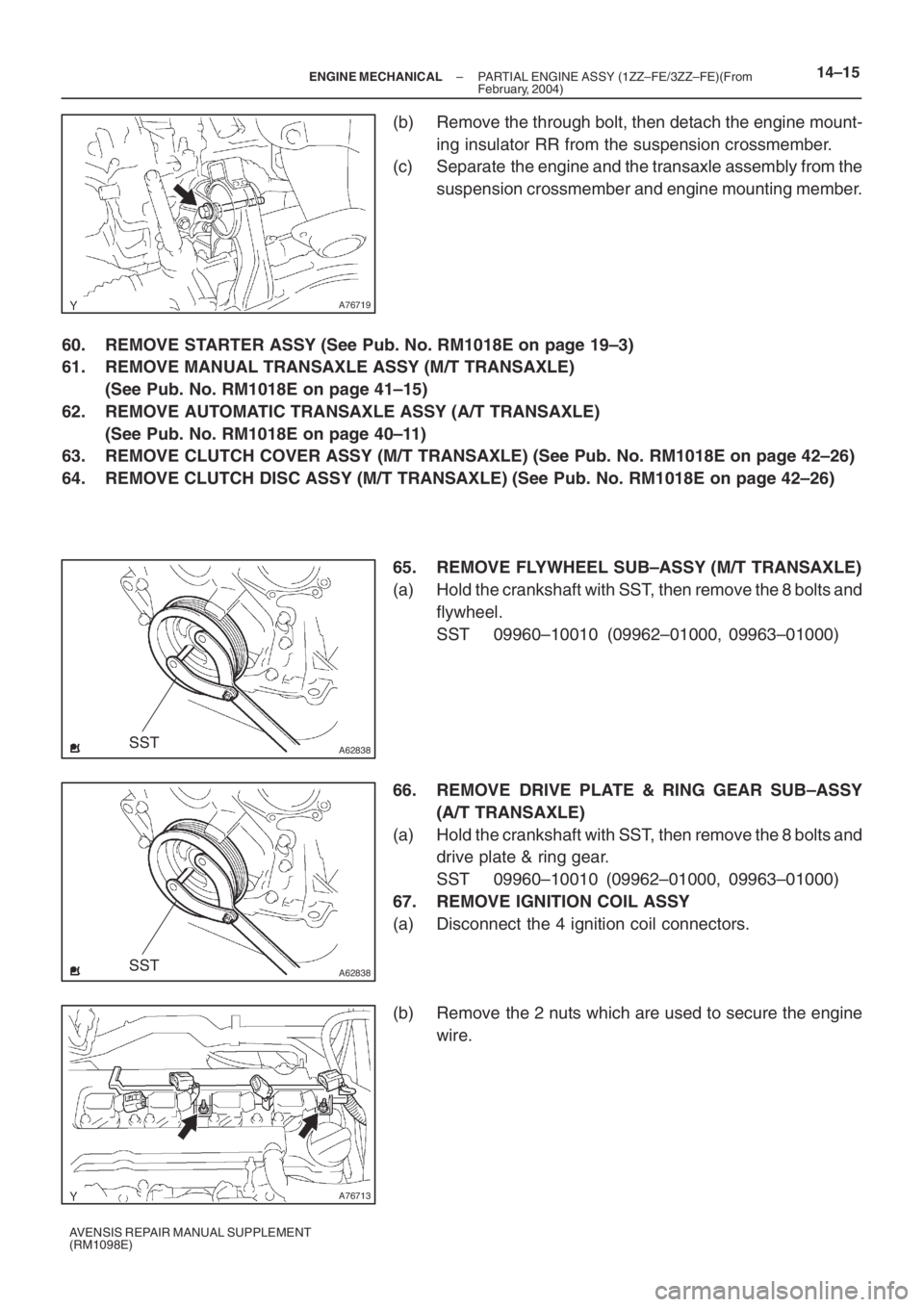
(b) Remove the through bolt, then detach the engine mount-
ing insulator RR from the suspension crossmember.
(c) Separate the engine and the transaxle assembly from the
suspension crossmember and engine mounting member.
60. REMOVE STARTER ASSY (See Pub. No. RM1018E on page 19–3)
61. REMOVE MANUAL TRANSAXLE ASSY (M/T TRANSAXLE)
(See Pub. No. RM1018E on page 41–15)
62. REMOVE AUTOMATIC TRANSAXLE ASSY (A/T TRANSAXLE)
(See Pub. No. RM1018E on page 40–11)
63. REMOVE CLUTCH COVER ASSY (M/T TRANSAXLE) (See Pub. No. RM1018E on page 42–26)
64. REMOVE CLUTCH DISC ASSY (M/T TRANSAXLE) (See Pub. No. RM1018E on page 42–26)
65. REMOVE FLYWHEEL SUB–ASSY (M/T TRANSAXLE)
(a) Hold the crankshaft with SST, then remove the 8 bolts and
flywheel.
SST 09960–10010 (09962–01000, 09963–01000)
66. REMOVE DRIVE PLATE & RING GEAR SUB–ASSY
(A/T TRANSAXLE)
(a) Hold the crankshaft with SST, then remove the 8 bolts and
drive plate & ring gear.
SST 09960–10010 (09962–01000, 09963–01000)
67. REMOVE IGNITION COIL ASSY
(a) Disconnect the 4 ignition coil connectors.
(b) Remove the 2 nuts which are used to secure the engine
wire.
Page 5081 of 5135

A76719
A76718
A76717
A76717
A
B
A
B 14–24
– ENGINE MECHANICALPARTIAL ENGINE ASSY (1ZZ–FE/3ZZ–FE)(From
February, 2004)
AVENSIS REPAIR MANUAL SUPPLEMENT
(RM1098E)
114. INSTALL CLUTCH DISC ASSY (M/T TRANSAXLE) (See Pub. No. RM1018E on page 42–26)
SST 09301–00210
115. INSTALL CLUTCH COVER ASSY (M/T TRANSAXLE) (See Pub. No. RM1018E on page 42–26)
SST 09301–00210
116. INSTALL MANUAL TRANSAXLE ASSY (M/T TRANSAXLE)
(See Pub. No. RM1018E on page 41–15)
117. INSTALL AUTOMATIC TRANSAXLE ASSY (A/T TRANSAXLE)
(See Pub. No. RM1018E on page 40–11)
118. INSTALL STARTER ASSY (See Pub. No. RM1018E on page 19–3)
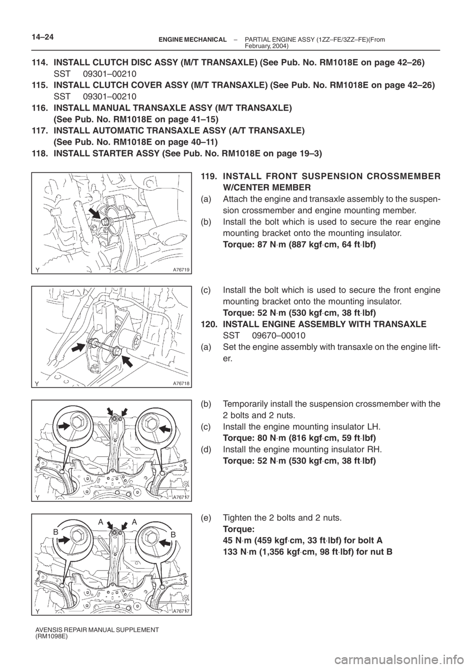
119. INSTALL FRONT SUSPENSION CROSSMEMBER
W/CENTER MEMBER
(a) Attach the engine and transaxle assembly to the suspen-
sion crossmember and engine mounting member.
(b) Install the bolt which is used to secure the rear engine
mounting bracket onto the mounting insulator.
Torque: 87 N⋅m (887 kgf⋅cm, 64 ft⋅lbf)
(c) Install the bolt which is used to secure the front engine
mounting bracket onto the mounting insulator.
Torque: 52 N⋅m (530 kgf⋅cm, 38 ft⋅lbf)
120. INSTALL ENGINE ASSEMBLY WITH TRANSAXLE
SST 09670–00010
(a) Set the engine assembly with transaxle on the engine lift-
er.
(b) Temporarily install the suspension crossmember with the
2 bolts and 2 nuts.
(c) Install the engine mounting insulator LH.
Torque: 80 N⋅m (816 kgf⋅cm, 59 ft⋅lbf)
(d) Install the engine mounting insulator RH.
Torque: 52 N⋅m (530 kgf⋅cm, 38 ft⋅lbf)
(e) Tighten the 2 bolts and 2 nuts.
Torque:
45 N⋅m (459 kgf⋅cm, 33 ft⋅lbf) for bolt A
133 N⋅m (1,356 kgf⋅cm, 98 ft⋅lbf) for nut B