Page 2696 of 5135
D30861
D30351
G20928
D25738
C85797
40±28
± AUTOMATIC TRANSMISSION / TRANSAUTOMATIC TRANSAXLE ASSY (U241E)
AVENSIS REPAIR MANUAL (RM1018E)
29. REMOVE TRANSVERSE ENGINE ENGINE
MOUNTING INSULATOR
(a) Remove the 4 bolts, nut and engine mounting insulator
LH.
30. REMOVE TRANSVERSE ENGINE ENGINE
MOUNTING BRACKET
(a) Remove the 3 bolts and engine mounting bracket LH from
the automatic transaxle.
31. REMOVE TRANSVERSE ENGINE ENGINE
MOUNTING INSULATOR
(a) Remove the bolt and separate the hose clamp from the
engine mounting insulator RR.
(b) Remove the bolt from the engine mounting bracket RR.
(c) Remove the 3 nuts, bolt and engine mounting insulator
RR from suspension member.
32. SEPARATE TRANSVERSE ENGINE ENGINE
MOUNTING INSULATOR
(a) Remove the bolt and nut from the engine mounting brack-
et FR.
Page 2710 of 5135
D31010
D30349
D30350
C87421
D25738
40±14
± AUTOMATIC TRANSMISSION / TRANSAUTOMATIC TRANSAXLE ASSY (U341E)
AVENSIS REPAIR MANUAL (RM1018E)
28. REMOVE TRANSVERSE ENGINE ENGINE
MOUNTING INSULATOR
(a) Remove the bolt and disconnect the wire harness clamp
bracket.
(b) Remove the 4 bolts, nut and engine mounting insulator
LH.
29. REMOVE TRANSVERSE ENGINE ENGINE
MOUNTING BRACKET
(a) Remove the 3 bolts and engine mounting bracket LH.
30. REMOVE TRANSVERSE ENGINE ENGINE
MOUNTING INSULATOR
(a) Remove the bolt from the engine mounting bracket RR.
(b) Remove the 3 nuts, bolt and engine mounting insulator
RR from the suspension member.
Page 2772 of 5135
A79193Engine Hanger No.1
Engine Hanger No.2
Engine Hanger No.1 UPR
D30072
D30073
±
MANUAL TRANSMISSION/TRANSAXLE MANUAL TRANSAXLE ASSY (1CD±FTV)
41±35
AVENSIS REPAIR MANUAL (RM1018E)
30.DISCONNECT STEERING GEAR OUTLET RETURN TUBE (See page 51±36)
SST 09023±12700
31.DISCONNECT PRESSURE FEED TUBE ASSY (See page 51±36)
SST 09023±12700
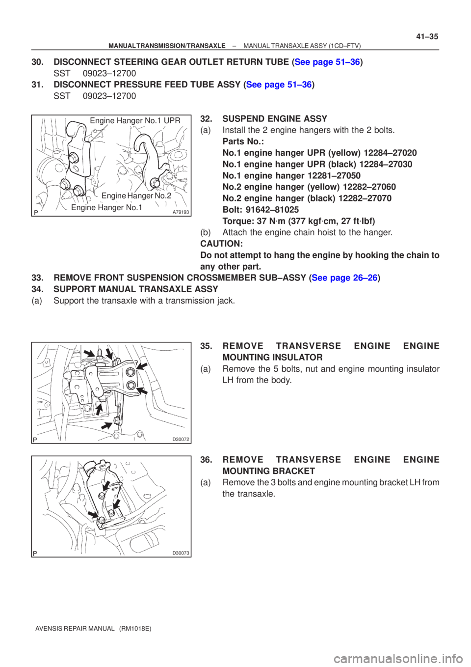
32. SUSPEND ENGINE ASSY
(a) Install the 2 engine hangers with the 2 bolts.Parts No.:
No.1 engine hanger UPR (yellow) 12284±27020
No.1 engine hanger UPR (black) 12284±27030
No.1 engine hanger 12281±27050
No.2 engine hanger (yellow) 12282±27060
No.2 engine hanger (black) 12282±27070
Bolt: 91642±81025
Torque: 37 N �m (377 kgf �cm, 27 ft �lbf)
(b) Attach the engine chain hoist to the hanger.
CAUTION:
Do not attempt to hang the engine by hooking the chain to
any other part.
33.REMOVE FRONT SUSPENSION CROSSMEMBER SUB±ASSY (See page 26±26)
34. SUPPORT MANUAL TRANSAXLE ASSY
(a) Support the transaxle with a transmission jack.
35. REMOVE TRANSVERSE ENGINE ENGINEMOUNTING INSULATOR
(a) Remove the 5 bolts, nut and engine mounting insulator LH from the body.
36. REMOVE TRANSVERSE ENGINE ENGINE MOUNTING BRACKET
(a) Remove the 3 bolts and engine mounting bracket LH from
the transaxle.
Page 2775 of 5135
G24413
G24412
AB
D26905
41±38
±
MANUAL TRANSMISSION/TRANSAXLE MANUAL TRANSAXLE ASSY (1CD±FTV)
AVENSIS REPAIR MANUAL (RM1018E)
47.INSTALL FRONT SUSPENSION CROSSMEMBER SUB±ASSY (See page 26±26) SST 09670±00010
48.CONNECT PRESSURE FEED TUBE ASSY (See page 51±36)
SST 09023±12700
49.CONNECT STEERING GEAR OUTLET RETURN TUBE (See page 51±36) SST 09023±12700
50. INSTALL HEIGHT CONTROL SENSOR SUB±ASSY FR RH (W/ DISCHARGE HEAD LAMP)
(See page 65±28)
51.INSTALL FRONT DRIVE SHAFT ASSY LH (See page 30±6)
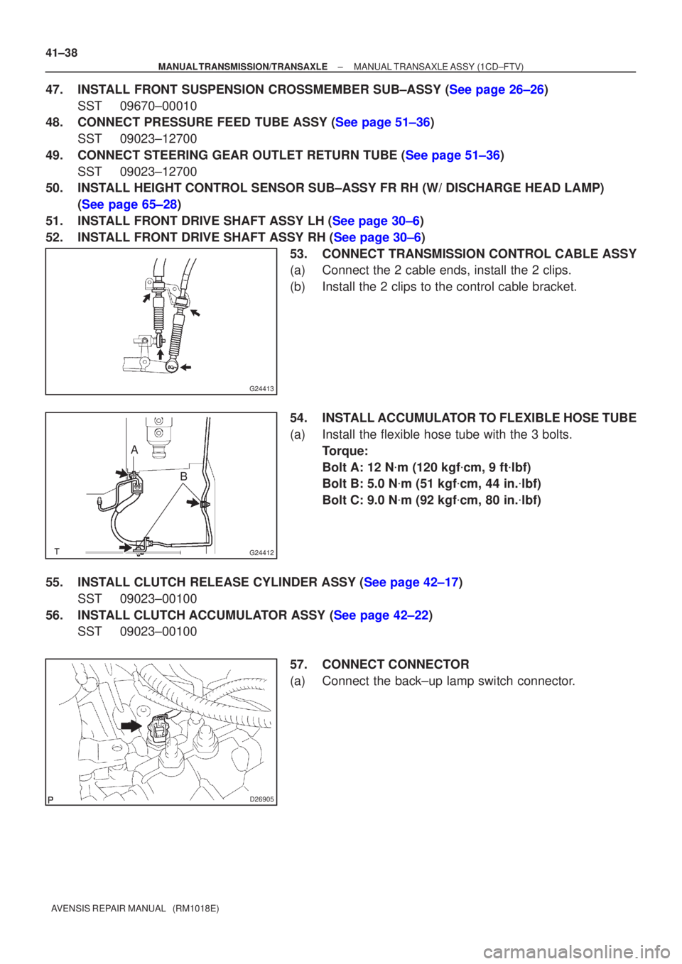
52.INSTALL FRONT DRIVE SHAFT ASSY RH (See page 30±6) 53. CONNECT TRANSMISSION CONTROL CABLE ASSY
(a) Connect the 2 cable ends, install the 2 clips.
(b) Install the 2 clips to the control cable bracket.
54. INSTALL ACCUMULATOR TO FLEXIBLE HOSE TUBE
(a) Install the flexible hose tube with the 3 bolts.Torque:
Bolt A: 12 N �m (120 kgf �cm, 9 ft �lbf)
Bolt B: 5.0 N �m (51 kgf �cm, 44 in. �lbf)
Bolt C: 9.0 N �m (92 kgf �cm, 80 in. �lbf)
55.INSTALL CLUTCH RELEASE CYLINDER ASSY (See page 42±17) SST 09023±00100
56.INSTALL CLUTCH ACCUMULATOR ASSY (See page 42±22) SST 09023±00100
57. CONNECT CONNECTOR
(a) Connect the back±up lamp switch connector.
Page 2782 of 5135
D25745
No.1 Engine Hanger No.2 Engine Hanger
D30067
D30077
D25747
41±26
±
MANUAL TRANSMISSION/TRANSAXLE MANUAL TRANSAXLE ASSY (1AZ±FE/1AZ±FSE)
AVENSIS REPAIR MANUAL (RM1018E)
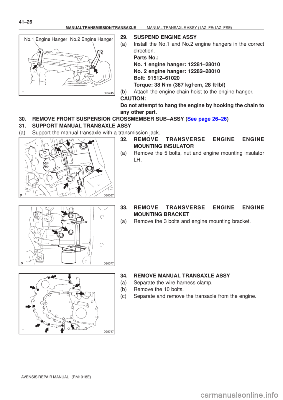
29. SUSPEND ENGINE ASSY
(a) Install the No.1 and No.2 engine hangers in the correct direction.
Parts No.:
No. 1 engine hanger: 12281±28010
No. 2 engine hanger: 12282±28010
Bolt: 91512±61020
Torque: 38 N �m (387 kgf �cm, 28 ft �lbf)
(b) Attach the engine chain hoist to the engine hanger.
CAUTION:
Do not attempt to hang the engine by hooking the chain to
any other part.
30.REMOVE FRONT SUSPENSION CROSSMEMBER SUB±ASSY (See page 26±26)
31. SUPPORT MANUAL TRANSAXLE ASSY
(a) Support the manual transaxle with a transmission jack. 32. REMOVE TRANSVERSE ENGINE ENGINE
MOUNTING INSULATOR
(a) Remove the 5 bolts, nut and engine mounting insulator LH.
33. REMOVE TRANSVERSE ENGINE ENGINE MOUNTING BRACKET
(a) Remove the 3 bolts and engine mounting bracket.
34. REMOVE MANUAL TRANSAXLE ASSY
(a) Separate the wire harness clamp.
(b) Remove the 10 bolts.
(c) Separate and remove the transaxle from the engine.
Page 2784 of 5135
D30076
D25747
AB
C
BA
D30077
D30067
A
A
A
A
B
41±28
±
MANUAL TRANSMISSION/TRANSAXLE MANUAL TRANSAXLE ASSY (1AZ±FE/1AZ±FSE)
AVENSIS REPAIR MANUAL (RM1018E)
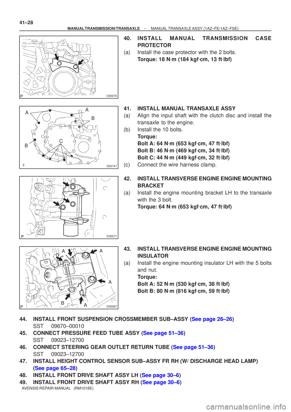
40. INSTALL MANUAL TRANSMISSION CASE PROTECTOR
(a) Install the case protector with the 2 bolts.
Torque: 18 N �m (184 kgf �cm, 13 ft �lbf)
41. INSTALL MANUAL TRANSAXLE ASSY
(a) Align the input shaft with the clutch disc and install the transaxle to the engine.
(b) Install the 10 bolts. Torque:
Bolt A: 64 N �m (653 kgf �cm, 47 ft �lbf)
Bolt B: 46 N �m (469 kgf �cm, 34 ft �lbf)
Bolt C: 44 N �m (449 kgf �cm, 32 ft �lbf)
(c) Connect the wire harness clamp.
42. INSTALL TRANSVERSE ENGINE ENGINE MOUNTING BRACKET
(a) Install the engine mounting bracket LH to the transaxle with the 3 bolt.
Torque: 64 N �m (653 kgf �cm, 47 ft �lbf)
43. INSTALL TRANSVERSE ENGINE ENGINE MOUNTING INSULATOR
(a) Install the engine mounting insulator LH with the 5 bolts and nut.
Torque:
Bolt A: 52 N �m (530 kgf �cm, 38 ft �lbf)
Bolt B: 80 N �m (816 kgf �cm, 59 ft �lbf)
44.INSTALL FRONT SUSPENSION CROSSMEMBER SUB±ASSY (See page 26±26) SST 09670±00010
45.CONNECT PRESSURE FEED TUBE ASSY (See page 51±36)
SST 09023±12700
46.CONNECT STEERING GEAR OUTLET RETURN TUBE (See page 51±36) SST 09023±12700
47. INSTALL HEIGHT CONTROL SENSOR SUB±ASSY FR RH (W/ DISCHARGE HEAD LAMP)
(See page 65±28)
48.INSTALL FRONT DRIVE SHAFT ASSY LH (See page 30±6)
49.INSTALL FRONT DRIVE SHAFT ASSY RH (See page 30±6)
Page 2791 of 5135
D25320
No.2 Engine Hanger
No.1 Engine Hanger
Front: Rear:
D30483
D30484
C70065
±
MANUAL TRANSMISSION/TRANSAXLE MANUAL TRANSAXLE ASSY (1ZZ±FE/3ZZ±FE)
41±17
AVENSIS REPAIR MANUAL (RM1018E)
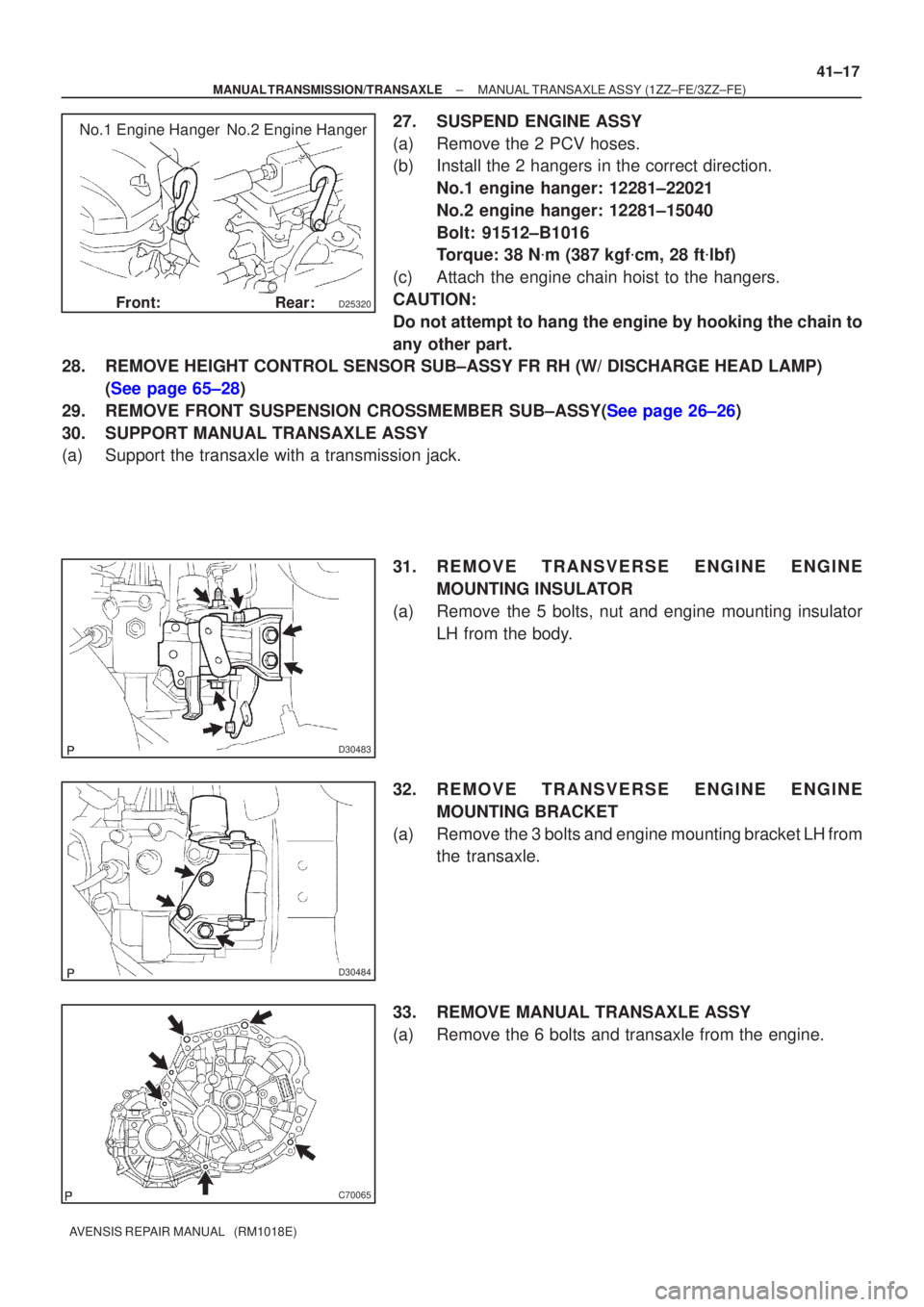
27. SUSPEND ENGINE ASSY
(a) Remove the 2 PCV hoses.
(b) Install the 2 hangers in the correct direction.
No.1 engine hanger: 12281±22021
No.2 engine hanger: 12281±15040
Bolt: 91512±B1016
Torque: 38 N �m (387 kgf �cm, 28 ft �lbf)
(c) Attach the engine chain hoist to the hangers.
CAUTION:
Do not attempt to hang the engine by hooking the chain to
any other part.
28. REMOVE HEIGHT CONTROL SENSOR SUB±ASSY FR RH (W/ DISCHARGE HEAD LAMP)\
(See page 65±28)
29.REMOVE FRONT SUSPENSION CROSSMEMBER SUB±ASSY(See page 26±26)
30. SUPPORT MANUAL TRANSAXLE ASSY
(a) Support the transaxle with a transmission jack.
31. REMOVE TRANSVERSE ENGINE ENGINEMOUNTING INSULATOR
(a) Remove the 5 bolts, nut and engine mounting insulator LH from the body.
32. REMOVE TRANSVERSE ENGINE ENGINE MOUNTING BRACKET
(a) Remove the 3 bolts and engine mounting bracket LH from the transaxle.
33. REMOVE MANUAL TRANSAXLE ASSY
(a) Remove the 6 bolts and transaxle from the engine.
Page 2793 of 5135
D30484
D30483
A
A
A
A
B
D11561
(a)
(c)
(b)(a)
G24210
±
MANUAL TRANSMISSION/TRANSAXLE MANUAL TRANSAXLE ASSY (1ZZ±FE/3ZZ±FE)
41±19
AVENSIS REPAIR MANUAL (RM1018E)
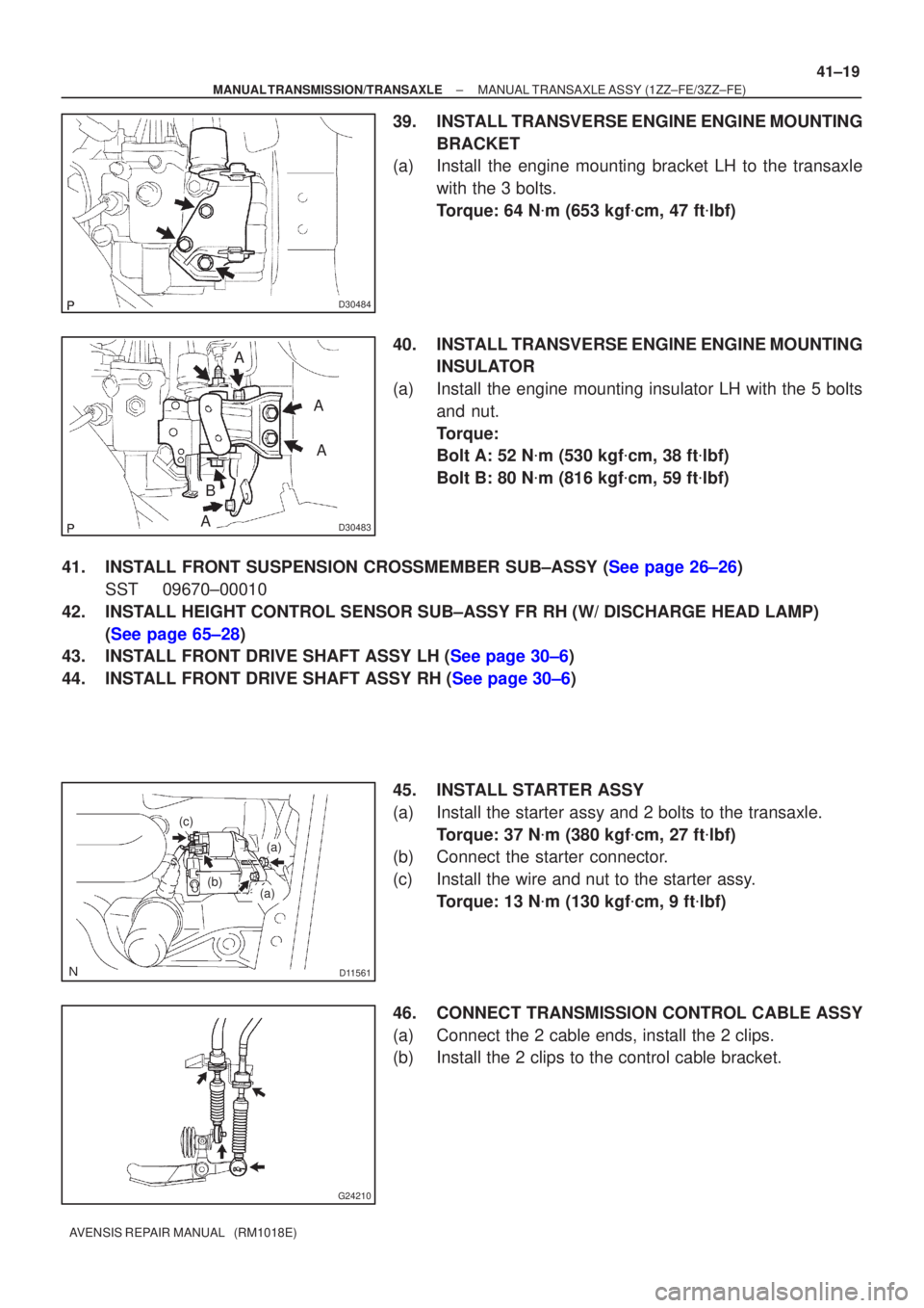
39. INSTALL TRANSVERSE ENGINE ENGINE MOUNTING
BRACKET
(a) Install the engine mounting bracket LH to the transaxle
with the 3 bolts.
Torque: 64 N �m (653 kgf �cm, 47 ft �lbf)
40. INSTALL TRANSVERSE ENGINE ENGINE MOUNTING INSULATOR
(a) Install the engine mounting insulator LH with the 5 bolts and nut.
Torque:
Bolt A: 52 N �m (530 kgf �cm, 38 ft �lbf)
Bolt B: 80 N �m (816 kgf �cm, 59 ft �lbf)
41.INSTALL FRONT SUSPENSION CROSSMEMBER SUB±ASSY (See page 26±26) SST 09670±00010
42. INSTALL HEIGHT CONTROL SENSOR SUB±ASSY FR RH (W/ DISCHARGE HEAD LAMP) (See page 65±28)
43.INSTALL FRONT DRIVE SHAFT ASSY LH (See page 30±6)
44.INSTALL FRONT DRIVE SHAFT ASSY RH (See page 30±6)
45. INSTALL STARTER ASSY
(a) Install the starter assy and 2 bolts to the transaxle.Torque: 37 N �m (380 kgf �cm, 27 ft �lbf)
(b) Connect the starter connector.
(c) Install the wire and nut to the starter assy.
Torque: 13 N �m (130 kgf �cm, 9 ft �lbf)
46. CONNECT TRANSMISSION CONTROL CABLE ASSY
(a) Connect the 2 cable ends, install the 2 clips.
(b) Install the 2 clips to the control cable bracket.