Page 2537 of 5135

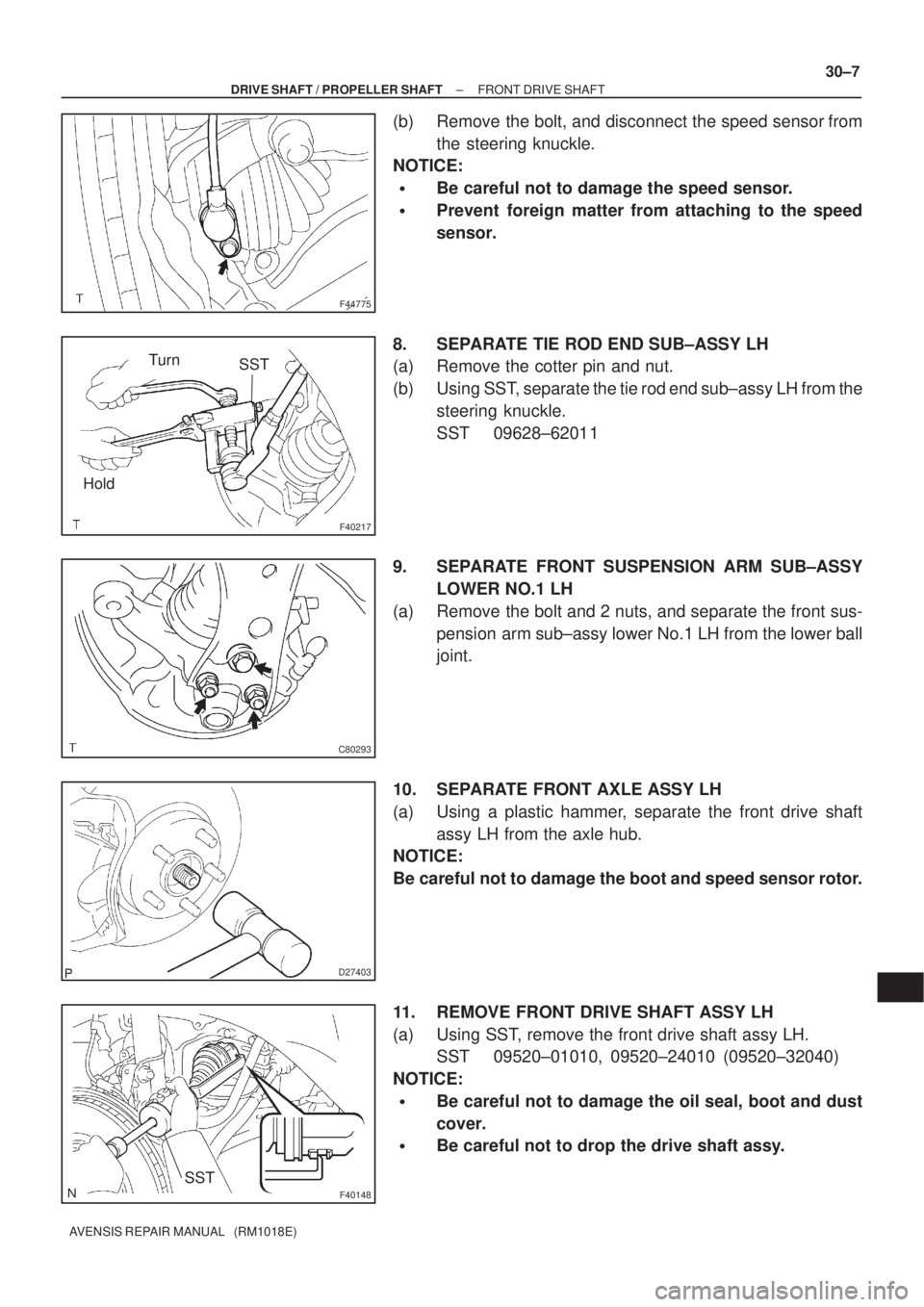
F44775
F40217
SSTTurn
Hold
C80293
D27403
F40148SST
± DRIVE SHAFT / PROPELLER SHAFTFRONT DRIVE SHAFT
30±7
AVENSIS REPAIR MANUAL (RM1018E)
(b) Remove the bolt, and disconnect the speed sensor from
the steering knuckle.
NOTICE:
�Be careful not to damage the speed sensor.
�Prevent foreign matter from attaching to the speed
sensor.
8. SEPARATE TIE ROD END SUB±ASSY LH
(a) Remove the cotter pin and nut.
(b) Using SST, separate the tie rod end sub±assy LH from the
steering knuckle.
SST 09628±62011
9. SEPARATE FRONT SUSPENSION ARM SUB±ASSY
LOWER NO.1 LH
(a) Remove the bolt and 2 nuts, and separate the front sus-
pension arm sub±assy lower No.1 LH from the lower ball
joint.
10. SEPARATE FRONT AXLE ASSY LH
(a) Using a plastic hammer, separate the front drive shaft
assy LH from the axle hub.
NOTICE:
Be careful not to damage the boot and speed sensor rotor.
11. REMOVE FRONT DRIVE SHAFT ASSY LH
(a) Using SST, remove the front drive shaft assy LH.
SST 09520±01010, 09520±24010 (09520±32040)
NOTICE:
�Be careful not to damage the oil seal, boot and dust
cover.
�Be careful not to drop the drive shaft assy.
Page 2549 of 5135

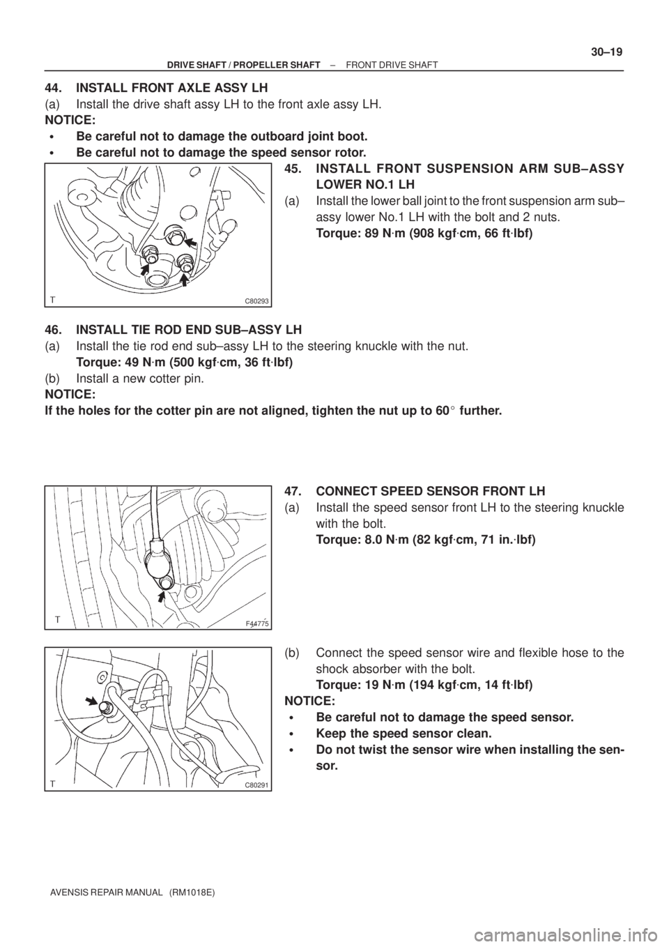
C80293
F44775
C80291
± DRIVE SHAFT / PROPELLER SHAFTFRONT DRIVE SHAFT
30±19
AVENSIS REPAIR MANUAL (RM1018E)
44. INSTALL FRONT AXLE ASSY LH
(a) Install the drive shaft assy LH to the front axle assy LH.
NOTICE:
�Be careful not to damage the outboard joint boot.
�Be careful not to damage the speed sensor rotor.
45. INSTALL FRONT SUSPENSION ARM SUB±ASSY
LOWER NO.1 LH
(a) Install the lower ball joint to the front suspension arm sub±
assy lower No.1 LH with the bolt and 2 nuts.
Torque: 89 N�m (908 kgf�cm, 66 ft�lbf)
46. INSTALL TIE ROD END SUB±ASSY LH
(a) Install the tie rod end sub±assy LH to the steering knuckle with the nut.
Torque: 49 N�m (500 kgf�cm, 36 ft�lbf)
(b) Install a new cotter pin.
NOTICE:
If the holes for the cotter pin are not aligned, tighten the nut up to 60� further.
47. CONNECT SPEED SENSOR FRONT LH
(a) Install the speed sensor front LH to the steering knuckle
with the bolt.
Torque: 8.0 N�m (82 kgf�cm, 71 in.�lbf)
(b) Connect the speed sensor wire and flexible hose to the
shock absorber with the bolt.
Torque: 19 N�m (194 kgf�cm, 14 ft�lbf)
NOTICE:
�Be careful not to damage the speed sensor.
�Keep the speed sensor clean.
�Do not twist the sensor wire when installing the sen-
sor.
Page 2551 of 5135
300JW±01
F44751
N�m (kgf�cm, ft�lbf) : Specified torque
Non±reusable parts �Front Suspension
Arm Sub±assy No.1 LH
89 (908, 66)
19 (194, 14)
74 (755, 55)
64 (650, 47)
49 (500, 36)
216 (2,200, 159)�
Front Axle Hub LH Nut Flexible Hose
Tie Rod End Sub±assy�Cotter Pin �Front Drive Shaft RH
Hole Snap Ring Front Drive Shaft Assy RH
Front Drive Shaft Assy RH 1AZ±FSE/
1AZ±FE/
1CD±FTV:
Speed Sensor Front LH
8.0 (82, 71 in.�lbf)
Front Drive Shaft Assy LH
Front Stabilizer Link Assy LH
3ZZ±FE/
1ZZ±FE:
64 (650, 47)
Front Drive Shaft Assy LH
3ZZ±FE/
1ZZ±FE/
1AZ±FSE (AT)/
1AZ±FE (AT):
1AZ±FSE (MT)/
1AZ±FE (MT)/
1CD±FTV:
�Front Drive Shaft LH
Hole Snap Ring
�Front Drive Shaft LH
Hole Snap Ring
± DRIVE SHAFT / PROPELLER SHAFTFRONT DRIVE SHAFT
30±3
AVENSIS REPAIR MANUAL (RM1018E)
FRONT DRIVE SHAFT
COMPONENTS
Page 2555 of 5135
3005C±02
±
DRIVE SHAFT / PROPELLER SHAFT DRIVE SHAFT, PROPELLER SHAFT, AXLE
30±1
AVENSIS REPAIR MANUAL (RM1018E)
DRIVE SHAFT, PROPELLER SHAFT, AXLE
PROBLEM SYMPTOMS TABLE
Use the table below to help you find the cause of the problem. The numbers \
indicate the priority of
the likely cause of the problem. Check each part in order. If necessary, replace these parts.
SymptomSuspect AreaSee page
Wander
5. Wheel
6. Front wheel alignment
7. Rear wheel alignment
8. Hub bearing (Worn)
9. Front shock absorber
10.Rear shock absorber28±1
26±6
27±4
30±2
26±10
27±8
Front wheel shimmy
1. Wheel (Imbalance)
2. Hub bearing (Worn)
3. Lower suspension arm ATM:
4. Lower suspension arm MTM:
5. Lower ball joint (Worm)
6. Front shock absorber28±1
30±2
26±16
26±21
26±24
26±10
Noise (Front)
1. Front drive shaft
2. Front shock absorber
3. Hub bearing (Worn)
4. Lower ball joint (Worm)30±6
26±10 30±2
26±24
Noise (Rear)1. Hub bearing (Worn)
2. Rear shock absorber30±2
27±8
Page 2558 of 5135

270E6±01
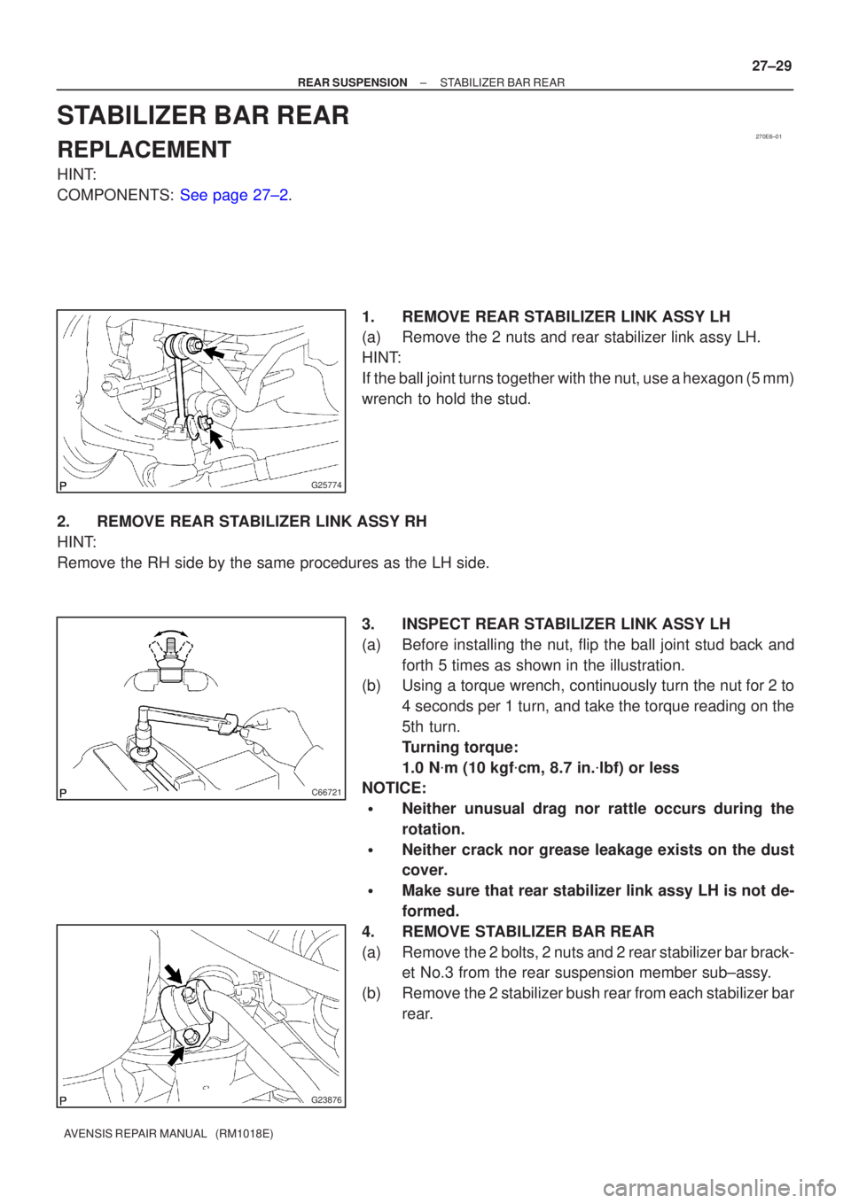
G25774
C66721
G23876
±
REAR SUSPENSION STABILIZER BAR REAR
27±29
AVENSIS REPAIR MANUAL (RM1018E)
STABILIZER BAR REAR
REPLACEMENT
HINT:
COMPONENTS: See page 27±2.
1. REMOVE REAR STABILIZER LINK ASSY LH
(a) Remove the 2 nuts and rear stabilizer link assy LH.
HINT:
If the ball joint turns together with the nut, use a hexagon (5 mm)
wrench to hold the stud.
2. REMOVE REAR STABILIZER LINK ASSY RH
HINT:
Remove the RH side by the same procedures as the LH side. 3. INSPECT REAR STABILIZER LINK ASSY LH
(a) Before installing the nut, flip the ball joint stud back andforth 5 times as shown in the illustration.
(b) Using a torque wrench, continuously turn the nut for 2 to
4 seconds per 1 turn, and take the torque reading on the
5th turn.
Turning torque:
1.0 N�m (10 kgf �cm, 8.7 in. �lbf) or less
NOTICE:
�Neither unusual drag nor rattle occurs during the
rotation.
�Neither crack nor grease leakage exists on the dust
cover.
�Make sure that rear stabilizer link assy LH is not de-
formed.
4. REMOVE STABILIZER BAR REAR
(a) Remove the 2 bolts, 2 nuts and 2 rear stabilizer bar brack- et No.3 from the rear suspension member sub±assy.
(b) Remove the 2 stabilizer bush rear from each stabilizer bar rear.
Page 2559 of 5135
G23878
Inner side
Stopper Ring
G23876
G25774
27±30
±
REAR SUSPENSION STABILIZER BAR REAR
AVENSIS REPAIR MANUAL (RM1018E)
5. INSTALL STABILIZER BAR REAR
(a) Install the 2 stabilizer bush rear to each stabilizer bar rear.
HINT:
Install the stabilizer bush rear to the outer side of the stopper
ring on the stabilizer bar.
(b) Install the stabilizer bar rear and 2 rear stabilizer bar bracket No.3 with 2 bolts and 2 nuts.
Torque: 35 N �m (357 kgf �cm, 26 ft �lbf)
6. INSTALL REAR STABILIZER LINK ASSY LH
(a) Install the rear stabilizer link assy LH with the 2 nuts. Torque: 44 N �m (449 kgf �cm, 32 ft �lbf)
HINT:
If the ball joint turns together with the nut, use a hexagon (5 mm)
wrench to hold the stud.
7. INSTALL REAR STABILIZER LINK ASSY RH
HINT:
Install the RH side by the same procedures as the LH side.
8.INSPECT AND ADJUST REAR WHEEL ALIGNMENT (See page 27±4)
Page 2560 of 5135
270E5±01
G25775
G21542
G23879
Matchmarks
G23879
Matchmarks
±
REAR SUSPENSION UPPER CONTROL ARM ASSY
27±27
AVENSIS REPAIR MANUAL (RM1018E)
UPPER CONTROL ARM ASSY
REPLACEMENT
HINT:
COMPONENTS: See page 27±2.
1. REMOVE REAR WHEEL
2. REMOVE UPPER CONTROL ARM ASSY
(a) Support the rear suspension arm assy No.1 LH.
(b) Remove the bolt and nut, separate the upper control armassy.
NOTICE:
When removing the bolt, hold the nut not to rotate.
(c) Place matchmarks on the camber adjust cam assy, cam- ber adjust cam No.2 and rear suspension member sub±
assy.
(d) Remove the nut, camber adjust cam assy and camber ad-
just cam No.2.
3. INSTALL UPPER CONTROL ARM ASSY
(a) Install the camber adjust cam assy from the front side of the vehicle, and temporarily fix it with the nut and the cam-
ber adjust cam No.2.
Page 2561 of 5135
G21542
G21542
G23879
Matchmarks
27±28
±
REAR SUSPENSION UPPER CONTROL ARM ASSY
AVENSIS REPAIR MANUAL (RM1018E)
(b) Install the upper control arm assy, and temporarily tighten the bolt and nut.
4. INSTALL REAR WHEEL Torque: 103 N �m (1,050 kgf �cm, 76 ft �lbf)
5.STABILIZE SUSPENSION (See page 27±8)
6. FULLY TIGHTEN UPPER CONTROL ARM ASSY
NOTICE:
Be sure to empty the vehicle when fully tightening the bolt
and nut.
(a) Fully tighten the bolt and nut.Torque: 74 N �m (755 kgf �cm, 55 ft �lbf)
NOTICE:
When instaling the bolt, hold the nut not to rotate.
(b) Align the matchmarks, and fully tighten the nut. Torque: 74 N �m (755 kgf �cm, 55 ft �lbf)
7.INSPECT AND ADJUST REAR WHEEL ALIGNMENT (See page 27±4)