Page 4043 of 5135

−
SERVICE SPECIFICATIONS ENGINE MECHANICAL
03−1 7
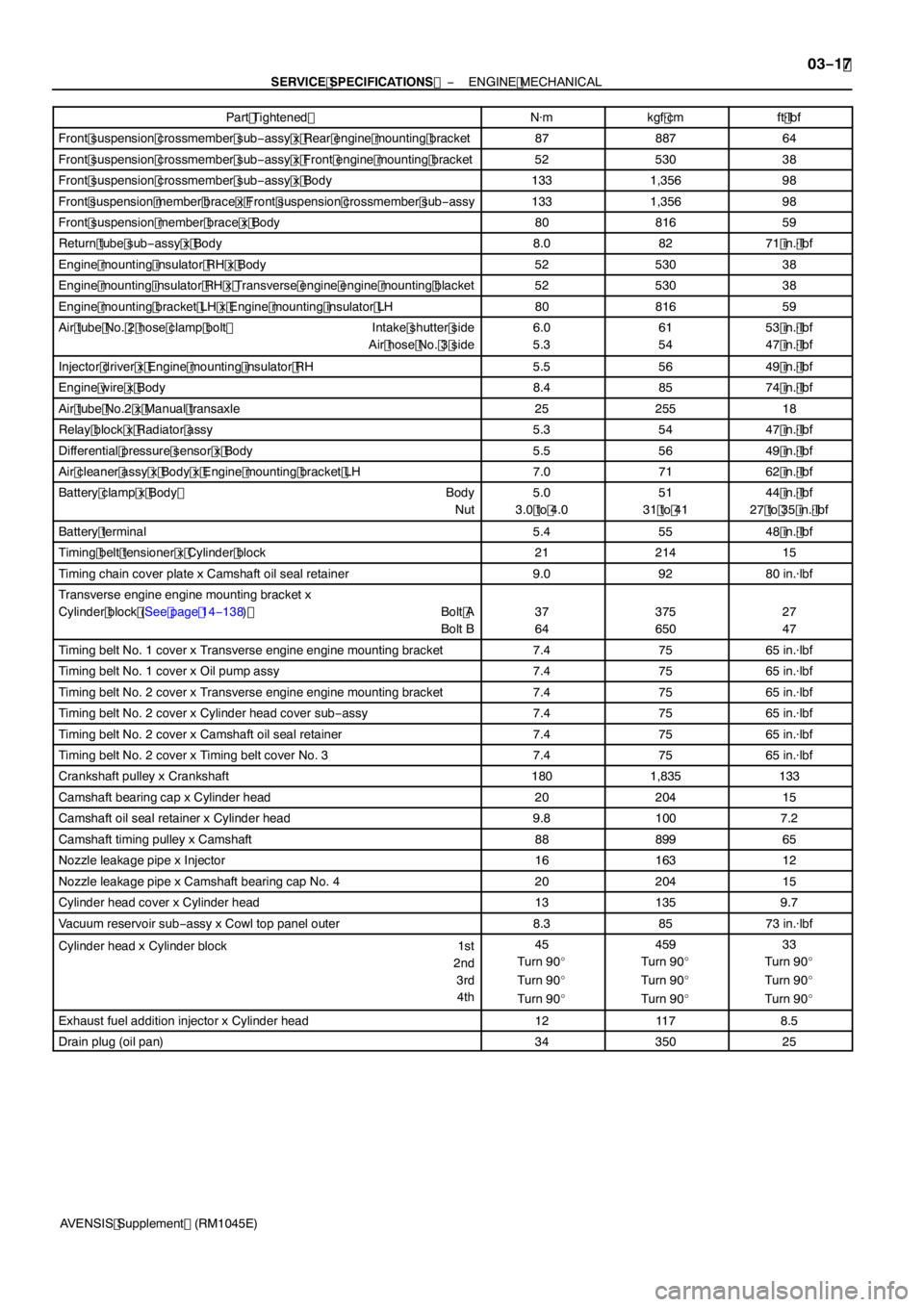
AVENSIS Supplement (RM1045E) Part Tightened
ft �lbf
kgf �cm
N �m
Front suspension crossmember sub −assy x Rear engine mounting bracket8788764
Front suspension crossmember sub −assy x Front engine mounting bracket5253038
Front suspension crossmember sub −assy x Body1331,35698
Front suspension member brace x Front suspension crossmember sub −assy1331,35698
Front suspension member brace x Body8081659
Return tube sub −assy x Body8.08271 in. �lbf
Engine mounting insulator RH x Body5253038
Engine mounting insulator RH x Transverse engine engine mounting blacket5253038
Engine mounting bracket LH x Engine mounting insulator LH8081659
Air tube No. 2 hose clamp bolt Intake shutter side
Air hose No. 3 side6.0
5.361
5453 in. �lbf
47 in. �lbf
Injector driver x Engine mounting insulator RH5.55649 in. �lbf
Engine wire x Body8.48574 in. �lbf
Air tube No.2 x Manual transaxle2525518
Relay block x Radiator assy5.35447 in. �lbf
Differential pressure sensor x Body5.55649 in. �lbf
Air cleaner assy x Body x Engine mounting bracket LH7.07162 in. �lbf
Battery clamp x Body Body
Nut5.0
3.0 to 4.051
31 to 4144 in. �lbf
27 to 35 in. �lbf
Battery terminal5.45548 in. �lbf
Timing belt tensioner x Cylinder block2121415
Timing chain cover plate x Camshaft oil seal retainer9.09280 in. �lbf
Transverse engine engine mounting bracket x
Cylinder block (See page 14 −138) Bolt A
Bolt B
37
64375
65027
47
Timing belt No. 1 cover x Transverse engine engine mounting bracket7.47565 in.�lbf
Timing belt No. 1 cover x Oil pump assy7.47565 in. �lbf
Timing belt No. 2 cover x Transverse engine engine mounting bracket7.47565 in. �lbf
Timing belt No. 2 cover x Cylinder head cover sub −assy7.47565 in. �lbf
Timing belt No. 2 cover x Camshaft oil seal retainer7.47565 in. �lbf
Timing belt No. 2 cover x Timing belt cover No. 37.47565 in. �lbf
Crankshaft pulley x Crankshaft1801,835133
Camshaft bearing cap x Cylinder head2020415
Camshaft oil seal retainer x Cylinder head9.81007.2
Camshaft timing pulley x Camshaft8889965
Nozzle leakage pipe x Injector1616312
Nozzle leakage pipe x Camshaft bearing cap No. 42020415
Cylinder head cover x Cylinder head131359.7
Vacuum reservoir sub −assy x Cowl top panel outer8.38573 in. �lbf
Cylinder head x Cylinder block 1st
2nd3rd4th45
Turn 90 _
Turn 90 _
Turn 90 _459
Turn 90 _
Turn 90 _
Turn 90 _33
Turn 90 _
Turn 90 _
Turn 90 _
Exhaust fuel addition injector x Cylinder head1211 78.5
Drain plug (oil pan)3435025
Page 4179 of 5135
− DIAGNOSTICSSFI SYSTEM (2AZ−FSE)
05−185
AVENSIS Supplement (RM1045E)
DTC P0504 BRAKE SWITCH ”A”/”B” CORRELATION
CIRCUIT DESCRIPTION
In addition to turning on the stop lamps, the stop lamp switch signals are used for a variety of engine, trans-
mission, and suspension functions as well as being an input for diagnostic checks. It is important that the
switch operates properly, therefore this switch is designed with two complementary signal output: STP and
ST1−. The ECM analyzes these signal output to detect malfunctions in the stop lamp switch.
HINT:
Normal condition is as shown in the table.
SignalBrake pedal releasedIn transitionBrake pedal depressed
STPOFFONON
ST1−ONONOFF
DTC No.DTC Detection ConditionTrouble Area
P0504
Condition (a), (b) and (c) continue for 0.5 second or more:
(a) Ignition switch ON
(b) Brake pedal released
(c) STP signal is OFF when the ST1−signal is OFFSShort in stop lamp switch signal circuit
SStop lamp switch
SECM
05CJ5−02
Page 4652 of 5135

A79140
−
ENGINE MECHANICAL PARTIAL ENGINE ASSY (1CD −FTV)(From September,
2003)14 −11 1
AVENSIS Supplement (RM1045E)
30. REMOVE CLUTCH ACCUMULATOR ASSY (See Pub. No. RM1018E on page 42 −22)
SST 09023 −00100
31. REMOVE CLUTCH RELEASE CYLINDER ASSY (See Pub. No. RM1018E on page 42 −17)
32. REMOVE V (COOLER COMPRESSOR TO CRANKSHAFT PULLEY) BELT NO.1
(See Pub. No. RM1018E on page 14 −269)
33. SEPARATE COMPRESSOR AND MAGNETIC CLUTCH (W/ AIR CONDITIONING)
(See Pub. No. RM1018E on page 55 −86)
HINT:
Secure the hoses off to the side instead of detaching.
34. REMOVE FLOOR PANEL BRACE FRONT (See page 15 −6)
35. REMOVE EXHAUST PIPE ASSY FRONT (See page 15 −6)
36. SEPARATE RETURN TUBE SUB −ASSY
(a) Remove the 2 clamp bolts, then separate the return tube
sub−assembly.
37. SEPARATE VANE PUMP OIL RESERVOIR ASSY
38. REMOVE FRONT AXLE HUB LH NUT (See Pub. No. RM1018E on page 30 −6)
SST 09930 −00010
HINT:
Perform the same procedure as above on the opposite side.
39. SEPARATE TIE ROD END SUB −ASSY LH (See Pub. No. RM1018E on page 30 −6)
SST 09628 −62011
HINT:
Perform the same procedure as above on the opposite side.
40. SEPARATE FRONT STABILIZER LINK ASSY LH (See Pub. No. RM1018E on page 30 −6)
HINT:
Perform the same procedure as above on the opposite side.
41. REMOVE COLUMN HOLE COVER SILENCER SHEET
(a) Remove the 2 clips and column hole cover silencer sheet.
42. REMOVE STEERING COLUMN HOLE COVER SUB −ASSY NO.1
43. REMOVE STEERING INTERMEDIATE SHAFT ASSY NO.2 (See Pub. No. RM1018E on page 51 −36)
44. SEPARATE FRONT SUSPENSION ARM SUB −ASSY LOWER NO.1 LH
(See Pub. No. RM1018E on page 30 −6)
HINT:
Perform the same procedure as above on the opposite side.
45. SEPARATE FRONT AXLE ASSY LH (See Pub. No. RM1018E on page 30 −6)
HINT:
Perform the same procedure as above on the opposite side.
Page 4653 of 5135
A79184
A85928
A61177
A59793
A59792
14−11 2− ENGINE MECHANICALPARTIAL ENGINE ASSY (1CD−FTV)(From September,
2003)
AVENSIS Supplement (RM1045E)
46. REMOVE ENGINE ASSEMBLY WITH TRANSAXLE
(a) Disconnect the height control sensor connector (with dis-
charge head lamp).
(b) Set the engine lifter.
(c) Remove the 3 bolts, 3 nuts and engine mounting insulator
sub−assembly RH.
(d) Remove the through bolt and nut, then detach the engine
mounting insulator LH from the vehicle.
(e) Remove the 8 bolts and front suspension member brace
rear RH and LH.
(f) Remove the 2 bolts and 2 nuts.
(g) Carefully remove the engine together with the transaxle
from the vehicle.
Page 4654 of 5135

A85927
Engine Hanger No. 1 Upper
Engine Hanger No. 2
Engine Hanger No. 1
A61175
A62711
A79180
− ENGINE MECHANICALPARTIAL ENGINE ASSY (1CD−FTV)(From September,
2003)14−11 3
AVENSIS Supplement (RM1045E)
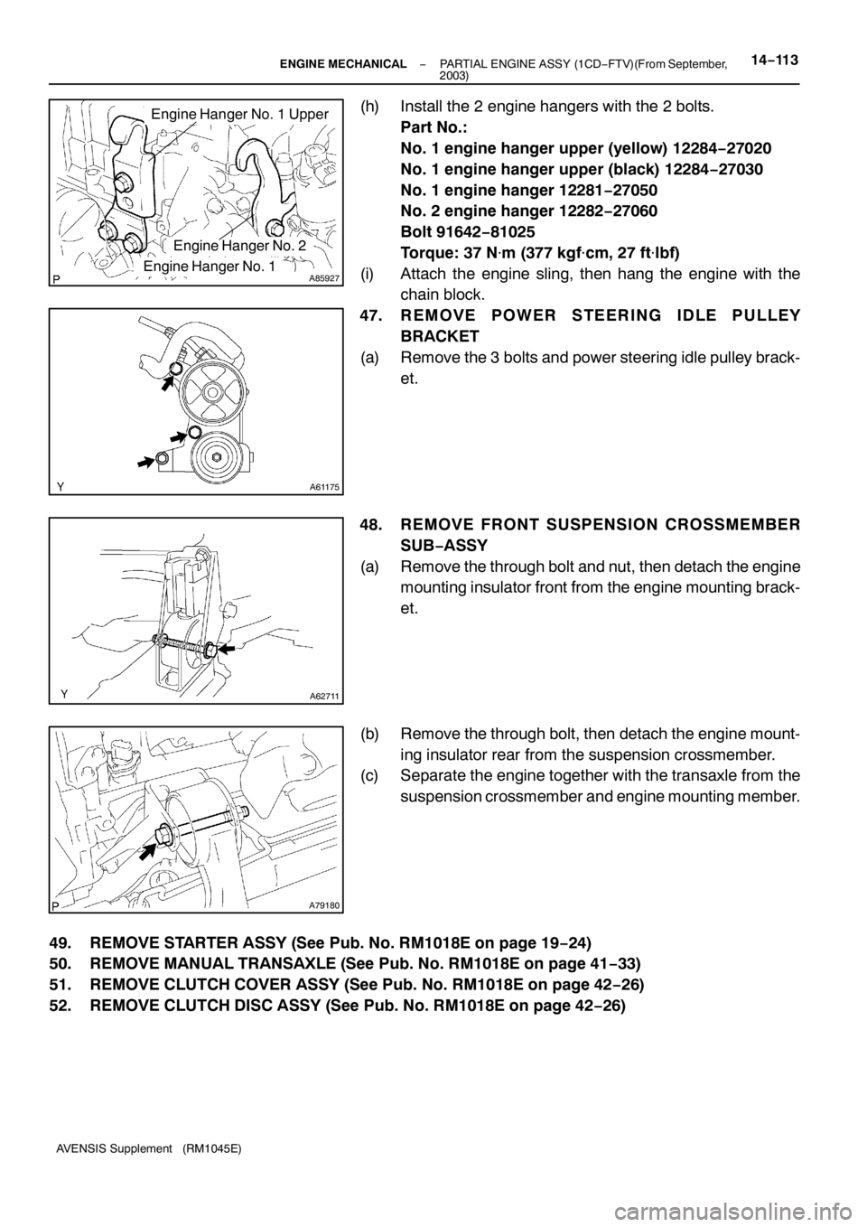
(h) Install the 2 engine hangers with the 2 bolts.
Part No.:
No. 1 engine hanger upper (yellow) 12284−27020
No. 1 engine hanger upper (black) 12284−27030
No. 1 engine hanger 12281−27050
No. 2 engine hanger 12282−27060
Bolt 91642−81025
Torque: 37 N�m (377 kgf�cm, 27 ft�lbf)
(i) Attach the engine sling, then hang the engine with the
chain block.
47. REMOVE POWER STEERING IDLE PULLEY
BRACKET
(a) Remove the 3 bolts and power steering idle pulley brack-
et.
48. REMOVE FRONT SUSPENSION CROSSMEMBER
SUB−ASSY
(a) Remove the through bolt and nut, then detach the engine
mounting insulator front from the engine mounting brack-
et.
(b) Remove the through bolt, then detach the engine mount-
ing insulator rear from the suspension crossmember.
(c) Separate the engine together with the transaxle from the
suspension crossmember and engine mounting member.
49. REMOVE STARTER ASSY (See Pub. No. RM1018E on page 19−24)
50. REMOVE MANUAL TRANSAXLE (See Pub. No. RM1018E on page 41−33)
51. REMOVE CLUTCH COVER ASSY (See Pub. No. RM1018E on page 42−26)
52. REMOVE CLUTCH DISC ASSY (See Pub. No. RM1018E on page 42−26)
Page 4671 of 5135

A79183
2
1
3
4
5
6
7
8
A79180
A62711
A61175
BA
A 14−130
− ENGINE MECHANICALPARTIAL ENGINE ASSY (1CD−FTV)(From September,
2003)
AVENSIS Supplement (RM1045E)
(d) Using a Torx socket wrench (T55), uniformly install and
tighten the 8 Torx screws in several steps in the sequence
shown in the illustration.
Torque: 71 N�m (720 kgf�cm, 52 ft�lbf)
184. INSTALL CLUTCH DISC ASSY (See Pub. No. RM1018E on page 42−26)
SST 09301−00210
185. INSTALL CLUTCH COVER ASSY (See Pub. No. RM1018E on page 42−26)
186. INSTALL MANUAL TRANSAXLE (See Pub. No. RM1018E on page 41−33)
187. INSTALL STARTER ASSY (See Pub. No. RM1018E on page 19−24)
188. INSTALL FRONT SUSPENSION CROSSMEMBER
SUB−ASSY
(a) Attach the engine together with the transaxle to the sus-
pension crossmember and engine mounting member.
(b) Install the bolt which secures the rear engine mounting
bracket to the mounting insulator.
Torque: 87 N�m (887 kgf�cm, 64 ft�lbf)
(c) Install the bolt which secures the front engine mounting
bracket to the mounting insulator.
Torque: 52 N�m (530 kgf�cm, 38 ft�lbf)
189. I N S TA L L P O W E R S T E E R I N G I D L E P U L L E Y
BRACKET
(a) Install the power steering idle pulley bracket with the 3
bolts.
Torque:
72 N�m (734 kgf�cm, 53 ft�lbf) for bolt A
39 N�m (398 kgf�cm, 29 ft�lbf) for bolt B
190. INSTALL ENGINE ASSEMBLY WITH TRANSAXLE
(a) Set the engine together with the transaxle on the engine
lifter.
Page 4672 of 5135
A59792
A61177
A85928
A59792
AA
BB
A59793
AA
BB
BBB
B
− ENGINE MECHANICALPARTIAL ENGINE ASSY (1CD−FTV)(From September,
2003)14−131
AVENSIS Supplement (RM1045E)
(b) Temporarily install the suspension crossmember with the
2 bolts and 2 nuts.
(c) Install the engine mounting insulator LH.
Torque: 80 N�m (816 kgf�cm, 59 ft�lbf)
(d) Install the engine mounting insulator RH.
Torque: 52 N�m (530 kgf�cm, 38 ft�lbf)
(e) Install the front suspension crossmember with the 2 bolts
and 2 nuts.
Torque:
45 N�m (459 kgf�cm, 33 ft�lbf) for bolt A
133 N�m (1,356 kgf�cm, 98 ft�lbf) for nut B
(f) Install the front suspension member brace LH and RH
with the 8 bolts.
Torque:
133 N�m (1,356 kgf�cm, 98 ft�lbf) for bolt A
80 N�m (816 kgf�cm, 59 ft�lbf) for bolt B
NOTICE:
After installing the crossmember, check that the position-
ing holes on the crossmember and vehicle are aligned.
Page 4673 of 5135

A93403
2to7mm
(0.0787 to
0.2756 in.)0to4mm
(0 to
0.1575 in.)
Intake Shutter Side:
Air Hose No. 3 Side:
4to12mm
(0.1575 to
0.4724 in.)
14
−132
−
ENGINE MECHANICAL PARTIAL ENGINE ASSY (1CD −FTV)(From September,
2003)
AVENSIS Supplement (RM1045E)
191. INSTALL FRONT AXLE ASSY LH (See Pub. No. RM1018E on page 30 −6)
HINT:
Perform the same procedure as above on the opposite side.
192. INSTALL FRONT SUSPENSION ARM SUB −ASSY LOWER NO.1 LH
(See Pub. No. RM1018E on page 30 −6)
HINT:
Perform the same procedure as above on the opposite side.
193. INSTALL STEERING INTERMEDIATE SHAFT ASSY NO.2
(See Pub. No. RM1018E on page 51 −36)
194. INSTALL FRONT STABILIZER LINK ASSY LH (See Pub. No. RM1018E on page 30 −6)
HINT:
Perform the same procedure as above on the opposite side.
195. INSTALL TIE ROD END SUB −ASSY LH (See Pub. No. RM1018E on page 30 −6)
HINT:
Perform the same procedure as above on the opposite side.
196. INSTALL FRONT AXLE HUB LH NUT (See Pub. No. RM1018E on page 30 −6)
HINT:
Perform the same procedure as above on the opposite side.
197. INSTALL RETURN TUBE SUB −ASSY
Torque: 8.0 N �m (82 kgf �cm, 71 in. �lbf)
198. INSTALL EXHAUST PIPE ASSY FRONT (See page 15 −6)
199. INSTALL FLOOR PANEL BRACE FRONT (See page 15 −6)
200. INSTALL COMPRESSOR AND MAGNETIC CLUTCH (W/ AIR CONDITIONING) (See Pub. No. RM1018E on page 55 −86)
201. ADJUST V (COOLER COMPRESSOR TO CRANKSHAFT PULLEY) BELT NO.1 (See Pub. No. RM1018E on page 14 −269)
202. INSTALL CLUTCH RELEASE CYLINDER ASSY (See Pub. No. RM1018E on page 42 −17)
203. INSTALL CLUTCH ACCUMULATOR ASSY (See Pub. No. RM1018E on page 42 −22)
SST 09023 −00100
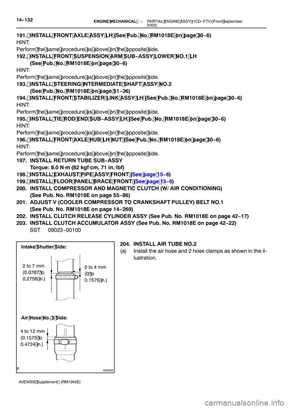
204. INSTALL AIR TUBE NO.2
(a) Install the air hose and 2 hose clamps as shown in the il-lustration.