Page 2756 of 5135

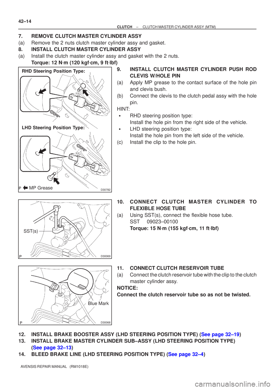
D30782
RHD Steering Position Type:
LHD Steering Position Type:
MP Grease
D30069
SST(s)
D30068
Blue Mark
42±14
±
CLUTCH CLUTCH MASTER CYLINDER ASSY (MTM)
AVENSIS REPAIR MANUAL (RM1018E)
7. REMOVE CLUTCH MASTER CYLINDER ASSY
(a) Remove the 2 nuts clutch master cylinder assy and gasket.
8. INSTALL CLUTCH MASTER CYLINDER ASSY
(a) Install the clutch master cylinder assy and gasket with the 2 nuts. Torque: 12 N �m (120 kgf �cm, 9 ft �lbf)
9. INSTALL CLUTCH MASTER CYLINDER PUSH ROD CLEVIS W/HOLE PIN
(a) Apply MP grease to the contact surface of the hole pin and clevis bush.
(b) Connect the clevis to the clutch pedal assy with the hole pin.
HINT:
�RHD steering position type:
Install the hole pin from the right side of the vehicle.
�LHD steering position type:
Install the hole pin from the left side of the vehicle.
(c) Install the clip to the hole pin.
10. CONNECT CLUTCH MASTER CYLINDER TO FLEXIBLE HOSE TUBE
(a) Using SST(s), connect the flexible hose tube. SST 09023±00100
Torque: 15 N �m (155 kgf �cm, 11 ft �lbf)
11. CONNECT CLUTCH RESERVOIR TUBE
(a) Connect the clutch reservoir tube with the clip to the clutch master cylinder assy.
NOTICE:
Connect the clutch reservoir tube so as not be twisted.
12.INSTALL BRAKE BOOSTER ASSY (LHD STEERING POSITION TYPE) (See page 32±19)
13. INSTALL BRAKE MASTER CYLINDER SUB±ASSY (LHD STEERING POSITION TYPE) (See page 32±13)
14.BLEED BRAKE LINE (LHD STEERING POSITION TYPE) (See page 32±4)
Page 2757 of 5135
±
CLUTCH CLUTCH MASTER CYLINDER ASSY (MTM)
42±15
AVENSIS REPAIR MANUAL (RM1018E)
15. BLEED CLUTCH PIPE LINE
(a) Fill the brake reservoir tank with the clutch fluid and bleed clutch sys\
tem.
Torque: 8.4 N �m (85 kgf �cm, 73 in. �lbf)
16. CHECK AND ADJUST BRAKE PEDAL HEIGHT (LHD STEERING POSITION TYPE) (See page 32±6)
17.INSPECT AND ADJUST CLUTCH PEDAL SUB±ASSY (See page 42±2)
18. CHECK BRAKE FLUID LEAKAGE (LHD STEERING POSITION TYPE)
19. CHECK CLUTCH FLUID LEAKAGE
20. CHECK FLUID LEVEL IN RESERVOIR
Page 2758 of 5135
4202V±03
D30477
LHD Steering Position Type:
RHD Steering PositionType:Clutch Master Cylinder To Flexible Hose Tube
Clutch Reservoir Tube
Clutch Master Cylinder
Push Rod Clevis w/ Hole Pin�Gasket
Clip
Clutch Master Cylinder Assy
Clutch Master Cylinder To Flexible Hose Tube
Clutch Reservoir Tube
Clutch Master Cylinder
Push Rod Clevis w/ Hole Pin
Clutch Master Cylinder AssyClip�Gasket
N�m (kgf�cm, ft�lbf) : Specified torque
Non±reusable part �
12 (120, 9)
12 (120, 9)
15 (155, 11)
15 (155, 11)
MP grease
42±12
± CLUTCHCLUTCH MASTER CYLINDER ASSY (MTM)
AVENSIS REPAIR MANUAL (RM1018E)
CLUTCH MASTER CYLINDER ASSY (MTM)
COMPONENTS
Page 2759 of 5135
4206D±01
D30782
RHD Steering Position Type:
LHD Steering Position Type:
D26300
LHD Steering
Position Type:RHD Steering
Position Type:
42±6
±
CLUTCH CLUTCH PEDAL SUB±ASSY (MTM)
AVENSIS REPAIR MANUAL (RM1018E)
REPLACEMENT
1. REMOVE INSTRUMENT PANEL SUB±ASSY LOWER (LHD STEERING POSITION TYPE) (See page 71±11)
2.REMOVE COMBINATION METER ASSY (RHD STEERING POSITION TYPE) (See page 71±21)
3. REMOVE CLUTCH PEDAL SPRING
4. REMOVE CLUTCH MASTER CYLINDER PUSH RODCLEVIS W/HOLE PIN
(a) Remove the clip and hole pin.
5. REMOVE CLUTCH PEDAL SUPPORT SUB±ASSY
(a) LHD steering position type: Remove the 2 nuts, bolt and clutch pedal support assy.
(b) RHD steering position type:
Remove the 2 bolts, 2 nuts and clutch pedal support assy.
Page 2760 of 5135
D30775
D30776
D30781
D30780
± CLUTCHCLUTCH PEDAL SUB±ASSY (MTM)
42±7
AVENSIS REPAIR MANUAL (RM1018E)
6. REMOVE TURN OVER SPRING SEAT COMPRESSION
SPRING (W/ TURN OVER)
(a) Mount the clutch pedal in a soft jaw vise.
(b) Using a screwdriver, remove the spring.
7. REMOVE CLUTCH PEDAL TURNOVER BUSH (W/
TURN OVER)
8. REMOVE CLUTCH PEDAL TURNOVER BUSH (W/
TURN OVER)
(a) Using a 8 mm hexagon wrench and a hammer, remove
the turn over bush.
9. REMOVE CLUTCH PEDAL SUB±ASSY
(a) Remove the bolt and nut.
(b) Remove the clutch pedal from the clutch pedal support.
10. REMOVE CLUTCH PEDAL PAD
11. REMOVE CLUTCH PEDAL BUSH
(a) Remove the 2 bushes from the clutch pedal.
Page 2761 of 5135
D30779
LHD Steering Position Type:
RHD Steering Position Type:
D30777
D30778MP Grease 42±8
± CLUTCHCLUTCH PEDAL SUB±ASSY (MTM)
AVENSIS REPAIR MANUAL (RM1018E)
12. REMOVE CLUTCH PEDAL NO.1 CUSHION
(a) LHD steering position type:
Using needle±nose pliers, remove the No.1 cushion from
the clutch pedal.
(b) RHD steering position type:
Using needle±nose pliers, remove the 2 No.1 cushions
from the clutch pedal.
13. REMOVE CLUTCH MASTER CYLINDER PUSH ROD
CLEVIS BUSH
(a) Using a 8 mm hexagon wrench and a hammer, remove
the clevis bush from the clutch pedal.
14. INSTALL CLUTCH MASTER CYLINDER PUSH ROD
CLEVIS BUSH
(a) Apply MP grease to the inside of a new clevis bush.
(b) Install the clevis bush to the clutch pedal.
HINT:
Install the clevis bush from the right side of the vehicle.
Page 2762 of 5135
D30779
LHD Steering Position Type:
RHD Steering Position Type:
D30780MP Grease
D30781
± CLUTCHCLUTCH PEDAL SUB±ASSY (MTM)
42±9
AVENSIS REPAIR MANUAL (RM1018E)
15. INSTALL CLUTCH PEDAL NO.1 CUSHION
(a) LHD steering position type:
Using needle±nose pliers, install the No.1 cushion to the
clutch pedal.
(b) RHD steering position type:
Using needle±nose pliers, install the 2 No.1 cushions to
the clutch pedal.
16. INSTALL CLUTCH PEDAL BUSH
(a) Apply MP grease to the inner, outer and end surface of 2
new bushes.
(b) Install the 2 bushes to the clutch pedal.
17. INSTALL CLUTCH PEDAL PAD
18. INSTALL CLUTCH PEDAL SUB±ASSY
(a) Install the clutch pedal to the clutch pedal support with the
bolt and nut.
Torque: 37 N�m (375 kgf�cm, 27 ft�lbf)
HINT:
Install the bolt from the right side of the vehicle.
Page 2763 of 5135

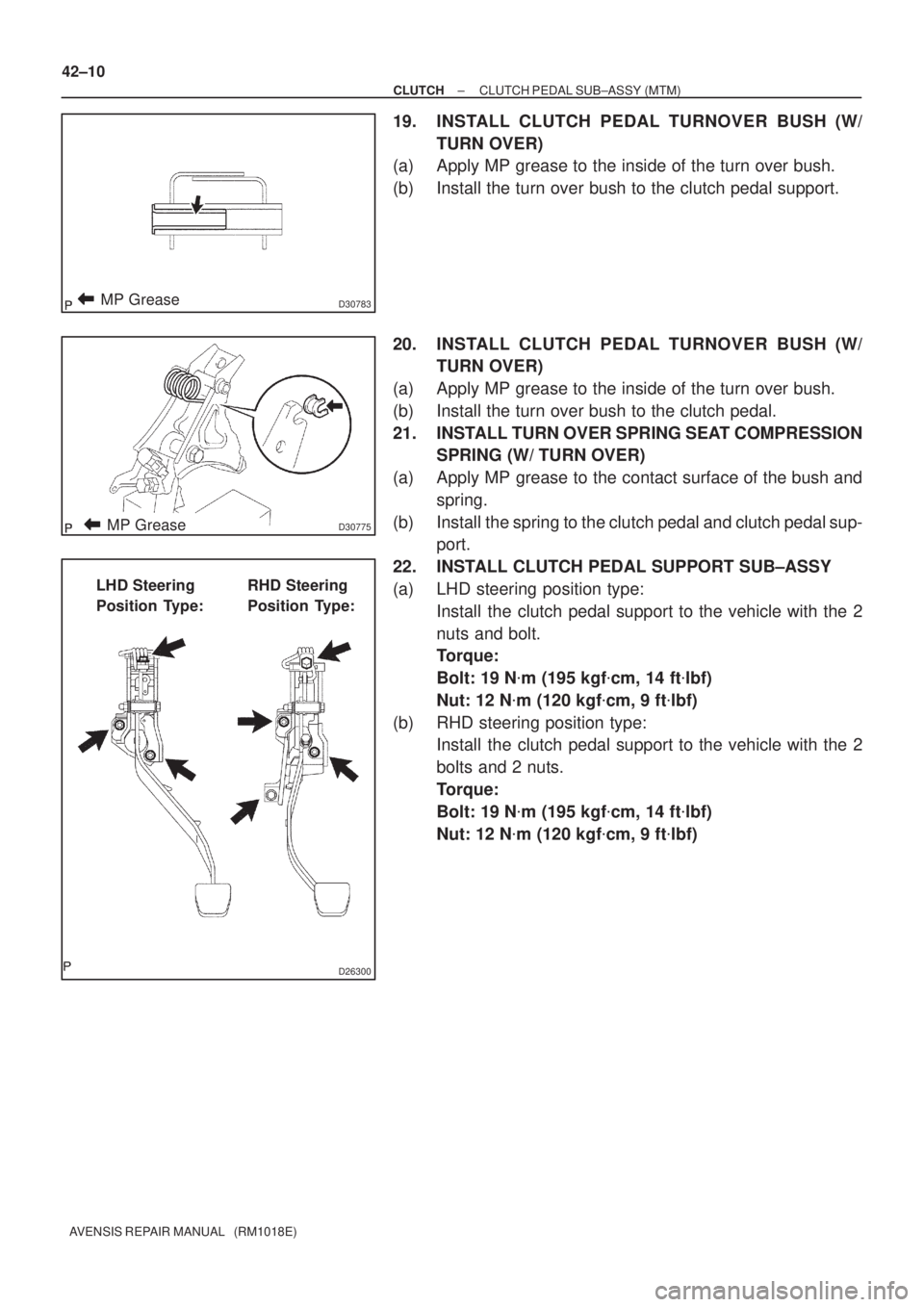
D30783MP Grease
D30775MP Grease
D26300
LHD Steering
Position Type:RHD Steering
Position Type: 42±10
± CLUTCHCLUTCH PEDAL SUB±ASSY (MTM)
AVENSIS REPAIR MANUAL (RM1018E)
19. INSTALL CLUTCH PEDAL TURNOVER BUSH (W/
TURN OVER)
(a) Apply MP grease to the inside of the turn over bush.
(b) Install the turn over bush to the clutch pedal support.
20. INSTALL CLUTCH PEDAL TURNOVER BUSH (W/
TURN OVER)
(a) Apply MP grease to the inside of the turn over bush.
(b) Install the turn over bush to the clutch pedal.
21. INSTALL TURN OVER SPRING SEAT COMPRESSION
SPRING (W/ TURN OVER)
(a) Apply MP grease to the contact surface of the bush and
spring.
(b) Install the spring to the clutch pedal and clutch pedal sup-
port.
22. INSTALL CLUTCH PEDAL SUPPORT SUB±ASSY
(a) LHD steering position type:
Install the clutch pedal support to the vehicle with the 2
nuts and bolt.
Torque:
Bolt: 19 N�m (195 kgf�cm, 14 ft�lbf)
Nut: 12 N�m (120 kgf�cm, 9 ft�lbf)
(b) RHD steering position type:
Install the clutch pedal support to the vehicle with the 2
bolts and 2 nuts.
Torque:
Bolt: 19 N�m (195 kgf�cm, 14 ft�lbf)
Nut: 12 N�m (120 kgf�cm, 9 ft�lbf)