Page 2323 of 5135
A79178
A78277
±
ENGINE MECHANICAL PARTIAL ENGINE ASSY(1CD±FTV)
14±287
AVENSIS REPAIR MANUAL (RM1018E)
24.SEPARATE TRANSMISSION CONTROL CABLE ASSY
(a)Remove the 2 clips and 2 washers, separate the control cable assy.
25.REMOVE INJECTOR DRIVER
(a)Remove the 2 nuts which is used to secure the injector driver.
(b)Disconnect the injector driver connector and the harness clamp.
(c)Remove the injector driver.
26.DISCONNECT ENGINE WIRE
(a)Remove the glove compartment door.
(b)Disconnect the engine wire from the ECM and the junc-
tion block.
(c)Pull out the engine wire.
(d)Disconnect the engine wire from engine room junction block.
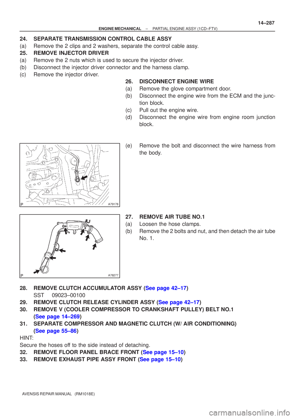
(e)Remove the bolt and disconnect the wire harness from the body.
27.REMOVE AIR TUBE NO.1
(a)Loosen the hose clamps.
(b)Remove the 2 bolts and nut, and then detach the air tube No. 1.
28.REMOVE CLUTCH ACCUMULATOR ASSY (See page 42±17) SST 09023±00100
29.REMOVE CLUTCH RELEASE CYLINDER ASSY (See page 42±17)
30. REMOVE V (COOLER COMPRESSOR TO CRANKSHAFT PULLEY) BELT NO.1
(See page 14±269)
31. SEPARATE COMPRESSOR AND MAGNETIC CLUTCH (W/ AIR CONDITIONING) (See page 55±86)
HINT:
Secure the hoses off to the side instead of detaching.
32.REMOVE FLOOR PANEL BRACE FRONT (See page 15±10)
33.REMOVE EXHAUST PIPE ASSY FRONT (See page 15±10)
Page 2326 of 5135
A62711
A79180
A61186
SST
14±290
±
ENGINE MECHANICAL PARTIAL ENGINE ASSY(1CD±FTV)
AVENSIS REPAIR MANUAL (RM1018E)
(i)Attach the engine sling and hang the engine with the chain block.
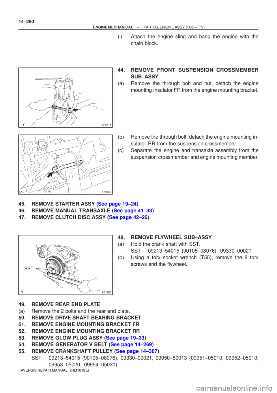
44.REMOVE FRONT SUSPENSION CROSSMEMBER SUB±ASSY
(a)Remove the through bolt and nut, detach the engine mounting insulator FR from the engine mounting bracket.
(b)Remove the through bolt, detach the engine mounting in- sulator RR from the suspension crossmember.
(c)Separate the engine and transaxle assembly from the suspension crossmember and engine mounting member.
45.REMOVE STARTER ASSY (See page 19±24)
46.REMOVE MANUAL TRANSAXLE (See page 41±33)
47.REMOVE CLUTCH DISC ASSY (See page 42±26) 48. REMOVE FLYWHEEL SUB±ASSY
(a) Hold the crank shaft with SST.SST 09213±54015 (90105±08076), 09330±00021
(b) Using a torx socket wrench (T55), remove the 8 torx
screws and the flywheel.
49. REMOVE REAR END PLATE
(a) Remove the 2 bolts and the rear end plate.
50. REMOVE DRIVE SHAFT BEARING BRACKET
51. REMOVE ENGINE MOUNTING BRACKET FR
52. REMOVE ENGINE MOUNTING BRACKET RR
53.REMOVE GLOW PLUG ASSY (See page 19±33)
54.REMOVE GENERATOR V BELT (See page 14±269)
55.REMOVE CRANKSHAFT PULLEY (See page 14±307) SST 09213±54015 (90105±08076), 09330±00021, 09950±50013 (0995\
1±05010, 09952±05010, 09953±05020, 09954±05031)
Page 2337 of 5135
A79183
2
1
3
4
5
6
7
8
A79180
A62711
A59792
±
ENGINE MECHANICAL PARTIAL ENGINE ASSY(1CD±FTV)
14±301
AVENSIS REPAIR MANUAL (RM1018E)
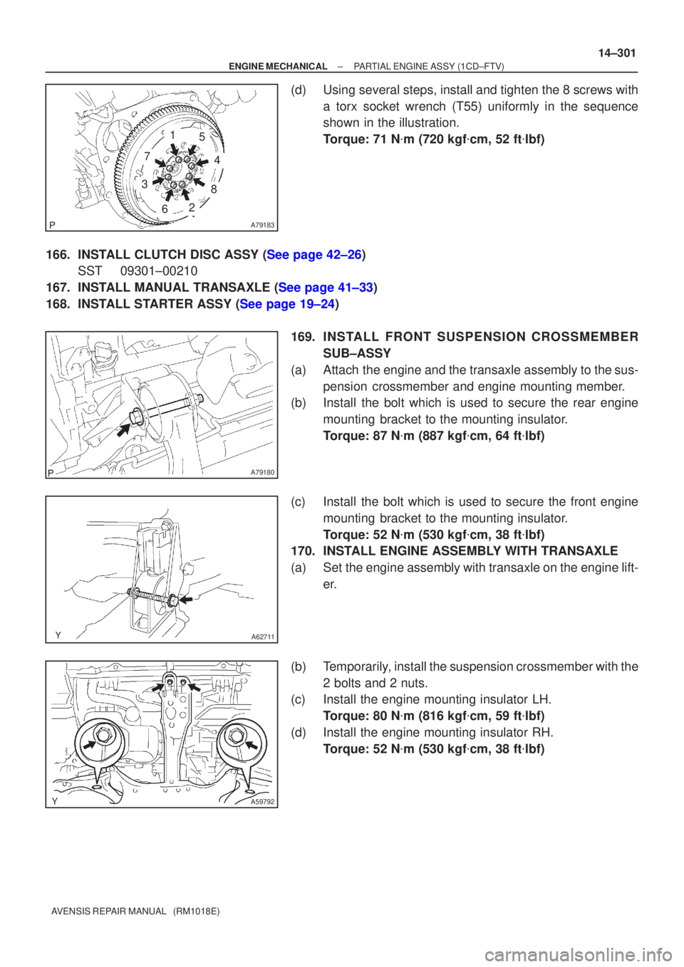
(d)Using several steps, install and tighten the 8 screws with
a torx socket wrench (T55) uniformly in the sequence
shown in the illustration.
Torque: 71 N �m (720 kgf �cm, 52 ft �lbf)
166.INSTALL CLUTCH DISC ASSY (See page 42±26) SST 09301±00210
167.INSTALL MANUAL TRANSAXLE (See page 41±33)
168.INSTALL STARTER ASSY (See page 19±24)
169. INS TALL FRO NT SUSPENSION CROSSMEMBER
SUB±ASSY
(a) Attach the engine and the transaxle assembly to the sus- pension crossmember and engine mounting member.
(b) Install the bolt which is used to secure the rear engine
mounting bracket to the mounting insulator.
Torque: 87 N �m (887 kgf �cm, 64 ft �lbf)
(c) Install the bolt which is used to secure the front engine mounting bracket to the mounting insulator.
Torque: 52 N �m (530 kgf �cm, 38 ft �lbf)
170. INSTALL ENGINE ASSEMBLY WITH TRANSAXLE
(a) Set the engine assembly with transaxle on the engine lift-
er.
(b) Temporarily, install the suspension crossmember with the 2 bolts and 2 nuts.
(c) Install the engine mounting insulator LH.
Torque: 80 N �m (816 kgf �cm, 59 ft �lbf)
(d) Install the engine mounting insulator RH. Torque: 52 N �m (530 kgf �cm, 38 ft �lbf)
Page 2338 of 5135
A59792
BB
AA
A59793
AA
BBBBB
B
14±302
±
ENGINE MECHANICAL PARTIAL ENGINE ASSY(1CD±FTV)
AVENSIS REPAIR MANUAL (RM1018E)
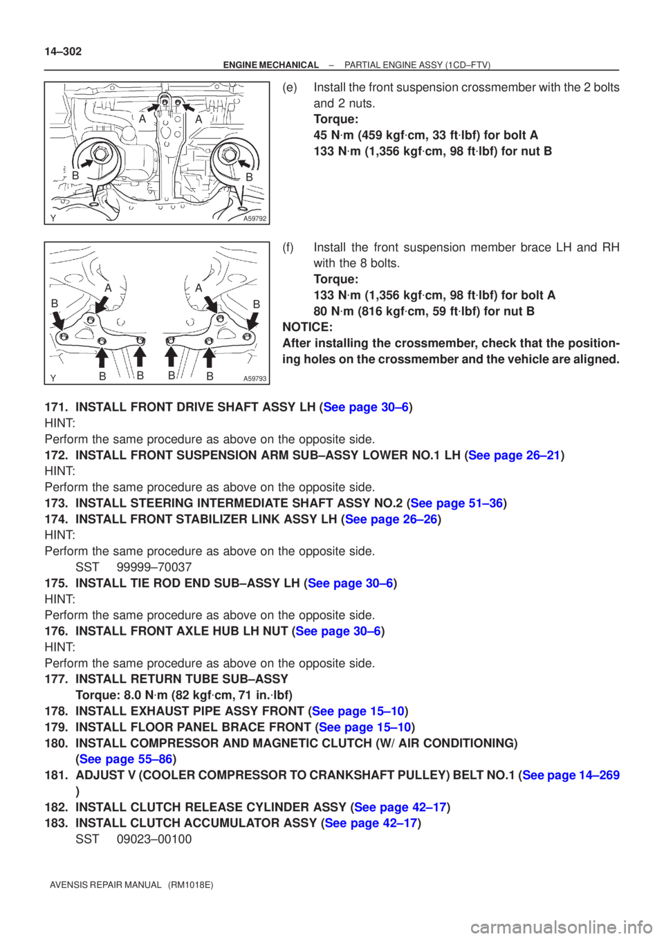
(e)Install the front suspension crossmember with the 2 bolts and 2 nuts.
Torque:
45 N�m (459 kgf �cm, 33 ft �lbf) for bolt A
133 N �m (1,356 kgf �cm, 98 ft �lbf) for nut B
(f)Install the front suspension member brace LH and RH with the 8 bolts.
Torque:
133 N �m (1,356 kgf �cm, 98 ft �lbf) for bolt A
80 N �m (816 kgf �cm, 59 ft �lbf) for nut B
NOTICE:
After installing the crossmember, check that the position-
ing holes on the crossmember and the vehicle are aligned.
171.INSTALL FRONT DRIVE SHAFT ASSY LH (See page 30±6)
HINT:
Perform the same procedure as above on the opposite side.
172.INSTALL FRONT SUSPENSION ARM SUB±ASSY LOWER NO.1 LH (See page 26±21)
HINT:
Perform the same procedure as above on the opposite side.
173.INSTALL STEERING INTERMEDIATE SHAFT ASSY NO.2 (See page 51±36)
174.INSTALL FRONT STABILIZER LINK ASSY LH (See page 26±26)
HINT:
Perform the same procedure as above on the opposite side. SST 99999±70037
175.INSTALL TIE ROD END SUB±ASSY LH (See page 30±6)
HINT:
Perform the same procedure as above on the opposite side.
176.INSTALL FRONT AXLE HUB LH NUT (See page 30±6)
HINT:
Perform the same procedure as above on the opposite side.
177. INSTALL RETURN TUBE SUB±ASSY Torque: 8.0 N �m (82 kgf �cm, 71 in. �lbf)
178.INSTALL EXHAUST PIPE ASSY FRONT (See page 15±10)
179.INSTALL FLOOR PANEL BRACE FRONT (See page 15±10)
180. INSTALL COMPRESSOR AND MAGNETIC CLUTCH (W/ AIR CONDITIONING) (See page 55±86)
181.ADJUST V (COOLER COMPRESSOR TO CRANKSHAFT PULLEY) BELT NO.1 (See page 14±269 )
182.INSTALL CLUTCH RELEASE CYLINDER ASSY (See page 42±17)
183.INSTALL CLUTCH ACCUMULATOR ASSY (See page 42±17) SST 09023±00100
Page 2340 of 5135
14±304
±
ENGINE MECHANICAL PARTIAL ENGINE ASSY (1CD±FTV)
AVENSIS REPAIR MANUAL (RM1018E)
191. INSTALL AIR CLEANER ASSY Torque: 7.0 N �m (71 kgf �cm, 62 in. �lbf)
192. INSTALL ENGINE COVER NO.1
Torque: 8.0 N �m (82 kgf �cm, 71 in. �lbf)
193.BLEED CLUTCH PIPE LINE (See page 42±17)
194. INSTALL FRONT WHEELS Torque: 103 N �m (1,050 kgf �cm, 76 ft �lbf)
195. ADD MANUAL TRANSAXLE OIL
196. ADD ENGINE OIL
197.ADD ENGINE COOLANT (See page 16±44)
198. CHECK CLUTCH FLUID LEAKAGE
199. CHECK FLUID LEVEL IN RESERVOIR
200. CHECK BRAKE FLUID LEAKAGE
201. CHECK FOR ENGINE OIL LEAKS
202.CHECK FOR FUEL LEAKS (See page 11±60)
203.CHECK FOR ENGINE COOLANT LEAKS (See page 16±44)
204. CHECK FOR EXHAUST GAS LEAKS
205.INSPECT AND ADJUST FRONT WHEEL ALIGNMENT (See page 26±6)
206.INSPECT ENGINE IDLE SPEED (See page 14±266)
207.CHECK ABS SPEED SENSOR SIGNAL (See page 05±756)
Page 2437 of 5135
190NO±01
A82615Terminal CTerminal 50
A82616Terminal C Terminal 50
A82617
Terminal C Terminal 50
± STARTING & CHARGINGSTARTING SYSTEM (1ZZ±FE/3ZZ±FE)
19±1
AVENSIS REPAIR MANUAL (RM1018E)
STARTING SYSTEM (1ZZ±FE/3ZZ±FE)
INSPECTION
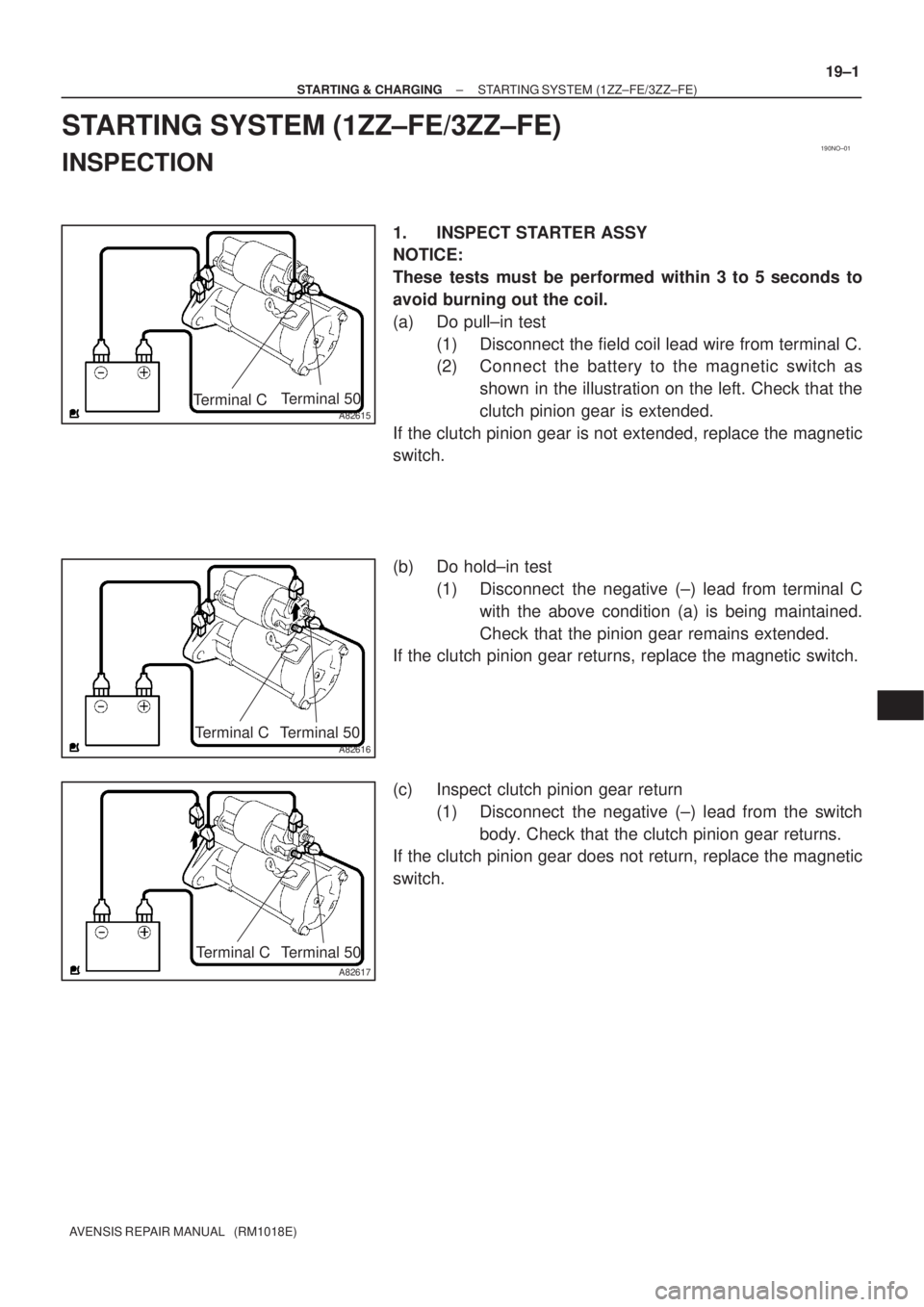
1. INSPECT STARTER ASSY
NOTICE:
These tests must be performed within 3 to 5 seconds to
avoid burning out the coil.
(a) Do pull±in test
(1) Disconnect the field coil lead wire from terminal C.
(2) Connect the battery to the magnetic switch as
shown in the illustration on the left. Check that the
clutch pinion gear is extended.
If the clutch pinion gear is not extended, replace the magnetic
switch.
(b) Do hold±in test
(1) Disconnect the negative (±) lead from terminal C
with the above condition (a) is being maintained.
Check that the pinion gear remains extended.
If the clutch pinion gear returns, replace the magnetic switch.
(c) Inspect clutch pinion gear return
(1) Disconnect the negative (±) lead from the switch
body. Check that the clutch pinion gear returns.
If the clutch pinion gear does not return, replace the magnetic
switch.
Page 2438 of 5135
A82618Terminal C Terminal 50
B16200
19±2
± STARTING & CHARGINGSTARTING SYSTEM (1ZZ±FE/3ZZ±FE)
AVENSIS REPAIR MANUAL (RM1018E)
(d) Do no±load performance test
(1) Connect the field coil lead wire to terminal C. Make
sure that the lead is not grounded.
Torque: 5.9 N�m (60 kgf�cm, 52 in�lbf)
(2) Clamp the starter in a vise.
(3) Connect the battery and an ammeter to the starter
as shown in the illustration.
(4) Check that the starter rotates smoothly and steadily
with the clutch pinion gear extended. Check that the
ammeter reads the specified current.
Specified current: 85 A or less at 11.5 V
2. INSPECT STARTER RELAY ASSY
(a) Continuity inspection.
(1) Using an ohmmeter, check for continuity between
each terminal.
Specified condition:
Terminal No.Specified condition
1 ± 2Continuity
No continuIty
3 ± 5Continuity
(Apply battery voltage terminals 1 and 2)
Page 2474 of 5135
190NL±01
A78633
Terminal CTerminal 50
A78634Disconnect
A78635
Disconnect
19±22
± STARTING & CHARGINGSTARTING SYSTEM (1CD±FTV)
AVENSIS REPAIR MANUAL (RM1018E)
STARTING SYSTEM (1CD±FTV)
INSPECTION
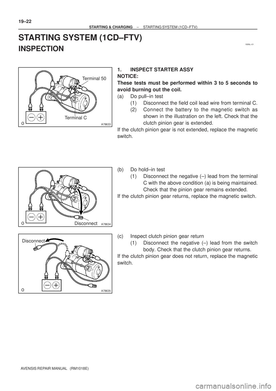
1. INSPECT STARTER ASSY
NOTICE:
These tests must be performed within 3 to 5 seconds to
avoid burning out the coil.
(a) Do pull±in test
(1) Disconnect the field coil lead wire from terminal C.
(2) Connect the battery to the magnetic switch as
shown in the illustration on the left. Check that the
clutch pinion gear is extended.
If the clutch pinion gear is not extended, replace the magnetic
switch.
(b) Do hold±in test
(1) Disconnect the negative (±) lead from the terminal
C with the above condition (a) is being maintained.
Check that the pinion gear remains extended.
If the clutch pinion gear returns, replace the magnetic switch.
(c) Inspect clutch pinion gear return
(1) Disconnect the negative (±) lead from the switch
body. Check that the clutch pinion gear returns.
If the clutch pinion gear does not return, replace the magnetic
switch.