Page 2475 of 5135
A78637
Terminal 30
Terminal 50
Ammeter
B16200
± STARTING & CHARGINGSTARTING SYSTEM (1CD±FTV)
19±23
AVENSIS REPAIR MANUAL (RM1018E)
(d) Do no±load performance test
(1) Connect the field coil lead wire to terminal C. Make
sure that the lead is not grounded.
Torque: 5.9 N�m (60 kgf�cm, 52 in�lbf)
(2) Clamp the starter in a vise.
(3) Connect the battery and an ammeter to the starter
as shown in the illustration.
(4) Check that the starter rotates smoothly and steadily
with the clutch pinion gear extended. Check that the
ammeter reads the specified current.
Specified current: 190 A or less at 11.5 V
2. INSPECT STARTER RELAY ASSY
(a) Continuity inspection.
(1) Using an ohmmeter, check for continuity between
each terminal.
Specified condition:
Terminal No.Specified condition
1 ± 2Continuity
No continuity
3 ± 5Continuity
(Apply battery voltage terminals 1 and 2)
Page 2486 of 5135

190NR±01
A78629
Terminal CTerminal 50
A78630Disconnect
A78631
Disconnect
19±10
± STARTING & CHARGINGSTARTING SYSTEM (1AZ±FSE)
AVENSIS REPAIR MANUAL (RM1018E)
STARTING SYSTEM (1AZ±FSE)
INSPECTION
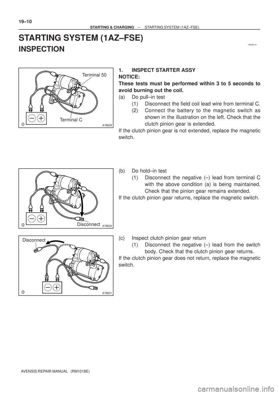
1. INSPECT STARTER ASSY
NOTICE:
These tests must be performed within 3 to 5 seconds to
avoid burning out the coil.
(a) Do pull±in test
(1) Disconnect the field coil lead wire from terminal C.
(2) Connect the battery to the magnetic switch as
shown in the illustration on the left. Check that the
clutch pinion gear is extended.
If the clutch pinion gear is not extended, replace the magnetic
switch.
(b) Do hold±in test
(1) Disconnect the negative (±) lead from terminal C
with the above condition (a) is being maintained.
Check that the pinion gear remains extended.
If the clutch pinion gear returns, replace the magnetic switch.
(c) Inspect clutch pinion gear return
(1) Disconnect the negative (±) lead from the switch
body. Check that the clutch pinion gear returns.
If the clutch pinion gear does not return, replace the magnetic
switch.
Page 2487 of 5135
A78632
Terminal 30
Terminal 50
Ammeter
B16200
± STARTING & CHARGINGSTARTING SYSTEM (1AZ±FSE)
19±11
AVENSIS REPAIR MANUAL (RM1018E)
(d) Do no±load performance test
(1) Connect the field coil lead wire to terminal C. Make
sure that the lead is not grounded.
Torque: 5.9 N�m (60 kgf�cm, 52 in�lbf)
(2) Clamp the starter in a vise.
(3) Connect the battery and an ammeter to the starter
as shown in the illustration.
(4) Check that the starter rotates smoothly and steadily
with the clutch pinion gear extended. Check that the
ammeter reads the specified current.
Specified current:
1.3kw 85 A or less at 11.5 V
1.6kw 75 A or less at 11.5 V
2. INSPECT STARTER RELAY ASSY
(a) Continuity inspection.
(1) Using an ohmmeter, check for continuity between
each terminal.
Specified condition:
Terminal No.Specified condition
1 ± 2Continuity
No continuity
3 ± 5Continuity
(Applying battery voltage terminals 1 and 2)
Page 2488 of 5135

190NU±01
A78629
Terminal CTerminal 50
A78630Disconnect
A78631
Disconnect
19±8
± STARTING & CHARGINGSTARTING SYSTEM (1AZ±FE)
AVENSIS REPAIR MANUAL (RM1018E)
STARTING SYSTEM (1AZ±FE)
INSPECTION
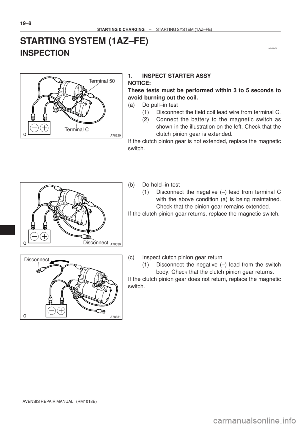
1. INSPECT STARTER ASSY
NOTICE:
These tests must be performed within 3 to 5 seconds to
avoid burning out the coil.
(a) Do pull±in test
(1) Disconnect the field coil lead wire from terminal C.
(2) Connect the battery to the magnetic switch as
shown in the illustration on the left. Check that the
clutch pinion gear is extended.
If the clutch pinion gear is not extended, replace the magnetic
switch.
(b) Do hold±in test
(1) Disconnect the negative (±) lead from terminal C
with the above condition (a) is being maintained.
Check that the pinion gear remains extended.
If the clutch pinion gear returns, replace the magnetic switch.
(c) Inspect clutch pinion gear return
(1) Disconnect the negative (±) lead from the switch
body. Check that the clutch pinion gear returns.
If the clutch pinion gear does not return, replace the magnetic
switch.
Page 2489 of 5135
A78632
Terminal 30
Terminal 50
Ammeter
B16200
± STARTING & CHARGINGSTARTING SYSTEM (1AZ±FE)
19±9
AVENSIS REPAIR MANUAL (RM1018E)
(d) Do no±load performance test
(1) Connect the field coil lead wire to terminal C. Make
sure that the lead is not grounded.
Torque: 5.9 N�m (60 kgf�cm, 52 in�lbf)
(2) Clamp the starter in a vise.
(3) Connect the battery and an ammeter to the starter
as shown in the illustration.
(4) Check that the starter rotates smoothly and steadily
with the clutch pinion gear extended. Check that the
ammeter reads the specified current.
Specified current: 85 A or less at 11.5 V
2. INSPECT STARTER RELAY ASSY
(a) Continuity inspection.
(1) Using an ohmmeter, check for continuity between
each terminal.
Specified condition:
Terminal No.Specified condition
1 ± 2Continuity
No continuity
3 ± 5Continuity
(Apply battery voltage terminals 1 and 2)
Page 2576 of 5135
F45161
Brake Master
Cylinder Sub±assy
Clutch Master Cylinder AssyM/T Transaxle: Vacuum Tank Diesel Engine Type:
Brake Fulid Level
Switch Connector Accelerator Control
Cable Support
20 (204, 15)
19 (194, 14)
Clutch Reservoir
Hose M/T Transaxle: Brake Booster Assy� Brake Booster Gasket
Brake Master Cylinder
ClevisClip Clevis Pin
13 (130, 9)
15 (155, 11) *1
29 (296, 21) *2
15 (155, 11)
N�m (kgf�cm, ft�lbf)
: Specified torque
5.4 (55, 48 in.�lbf)
8.3 (85, 73 in.�lbf)
Wave Washer
Check Valve Grommet
15 (155, 11)
5.4 (55, 48 in.�lbf)
*1 w/ ABS:
*2 w/ VSC:
32±24
± BRAKEBRAKE BOOSTER ASSY (RHD)
AVENSIS REPAIR MANUAL (RM1018E)
Page 2579 of 5135

F42620
F40019
32±20
±
BRAKE BRAKE BOOSTER ASSY (LHD)
AVENSIS REPAIR MANUAL (RM1018E)
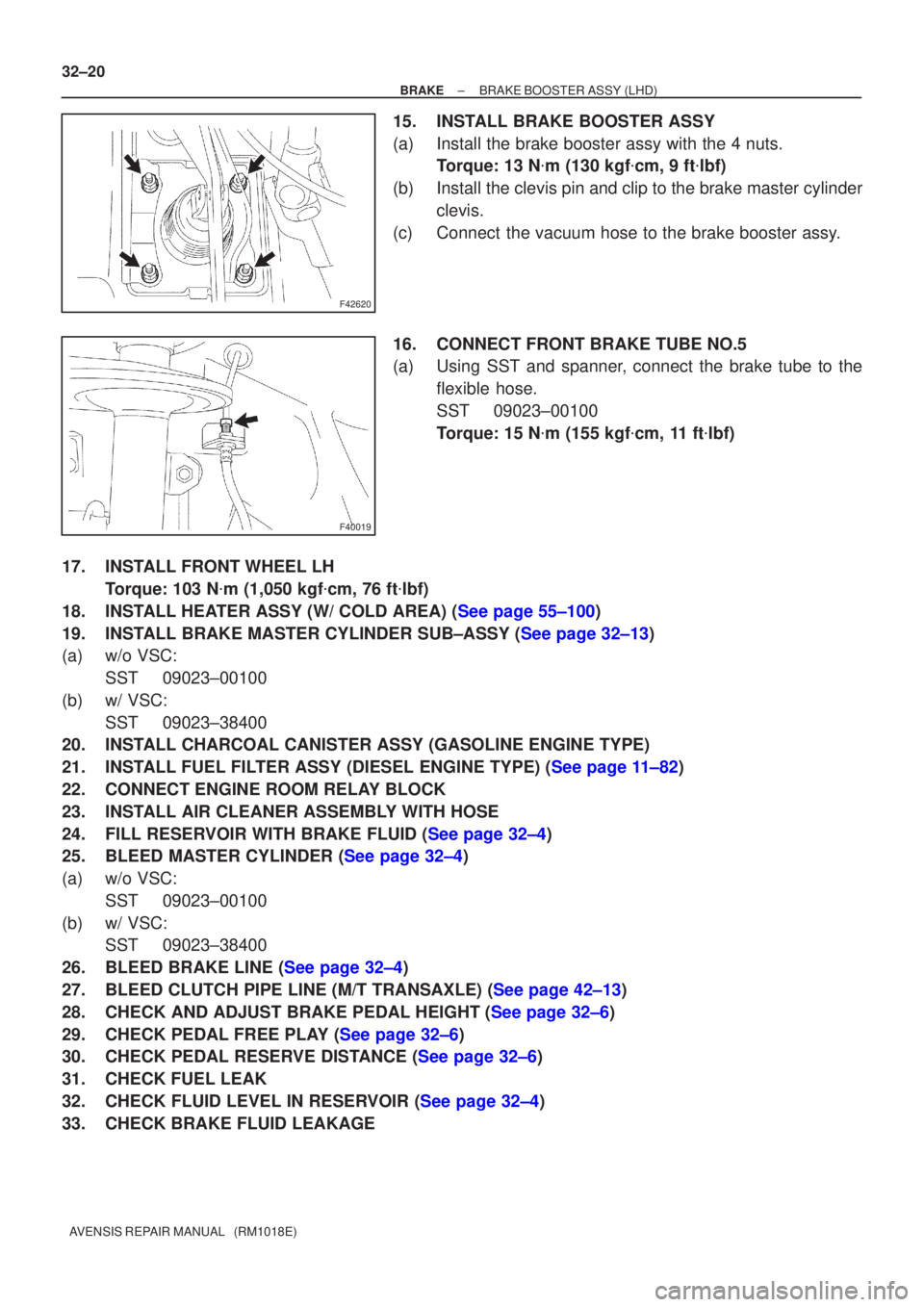
15. INSTALL BRAKE BOOSTER ASSY
(a) Install the brake booster assy with the 4 nuts. Torque: 13 N �m (130 kgf �cm, 9 ft �lbf)
(b) Install the clevis pin and clip to the brake master cylinder clevis.
(c) Connect the vacuum hose to the brake booster assy.
16. CONNECT FRONT BRAKE TUBE NO.5
(a) Using SST and spanner, connect the brake tube to the flexible hose.
SST 09023±00100
Torque: 15 N �m (155 kgf �cm, 11 ft �lbf)
17. INSTALL FRONT WHEEL LH Torque: 103 N �m (1,050 kgf �cm, 76 ft �lbf)
18.INSTALL HEATER ASSY (W/ COLD AREA) (See page 55±100)
19.INSTALL BRAKE MASTER CYLINDER SUB±ASSY (See page 32±13)
(a) w/o VSC: SST 09023±00100
(b) w/ VSC: SST 09023±38400
20. INSTALL CHARCOAL CANISTER ASSY (GASOLINE ENGINE TYPE)
21.INSTALL FUEL FILTER ASSY (DIESEL ENGINE TYPE) (See page 11±82)
22. CONNECT ENGINE ROOM RELAY BLOCK
23. INSTALL AIR CLEANER ASSEMBLY WITH HOSE
24.FILL RESERVOIR WITH BRAKE FLUID (See page 32±4)
25.BLEED MASTER CYLINDER (See page 32±4)
(a) w/o VSC:
SST 09023±00100
(b) w/ VSC: SST 09023±38400
26.BLEED BRAKE LINE (See page 32±4)
27.BLEED CLUTCH PIPE LINE (M/T TRANSAXLE) (See page 42±13)
28.CHECK AND ADJUST BRAKE PEDAL HEIGHT (See page 32±6)
29.CHECK PEDAL FREE PLAY (See page 32±6)
30.CHECK PEDAL RESERVE DISTANCE (See page 32±6)
31. CHECK FUEL LEAK
32.CHECK FLUID LEVEL IN RESERVOIR (See page 32±4)
33. CHECK BRAKE FLUID LEAKAGE
Page 2580 of 5135
320VU±01
F45162
Vacuum Hose
ClipBrake Vacuum
Check Valve
Check Valve
Grommet
Clevis Pin
Clip Wave Washer
13 (130, 9)
Engine Room Relay Block Way
Clutch Reservoir Tube M/T Transaxle:
Front Brake
Tube No.5
15 (155, 11) *1
29 (296, 21) *2
Brake Fluid Level
Switch Connector
� Brake Booster Gasket
20 (204, 15)
20 (204, 15)
Brake Master
Cylinder Sub±assy
� Brake Booster Assy
Brake Master
Cylinder clevis
15 (155, 11)
Fuel Filter Assy Diesel Engine Type: Heater Assy w/ Cold Area:
Air Cleaner Assembly
With Hose
Clutch Tube M/T Transaxle:Gasoline Engine Type:
15 (155, 11)
*1
w/ ABS:
*2
w/ VSC:N�m (kgf�cm, ft�lbf) : Specified torque
5.4 (55, 48 in.�lbf)
Charcoal Canister
Assy
32±18
± BRAKEBRAKE BOOSTER ASSY (LHD)
AVENSIS REPAIR MANUAL (RM1018E)
COMPONENTS