Page 1902 of 5135

110UD±01
A79188
A80091SST
A79190
11±82
± FUELFUEL FILTER ASSY (1CD±FTV)
AVENSIS REPAIR MANUAL (RM1018E)
FUEL FILTER ASSY (1CD±FTV)
REPLACEMENT
1. REMOVE AIR CLEANER ASSY
(a) Disconnect the connector.
(b) Remove the air cleaner cap with the air cleaner hose.
(c) Remove the air cleaner filter element.
(d) Remove the 3 bolts and the air cleaner case.
2. REMOVE FUEL FILTER ASSY
(a) Disconnect the 2 fuel hose from the fuel filter. (STD or COLD)
(b) Disconnect the 3 fuel hose from the fuel filter. (W/ ADDTIONAL HEATER)
(c) Disconnect the 2 connectors.
(d) Remove the 2 bolts and the fuel filter.
3. DRAIN FUEL
(a) Loosen the drain plug, and drain the fuel from the fuel filter.
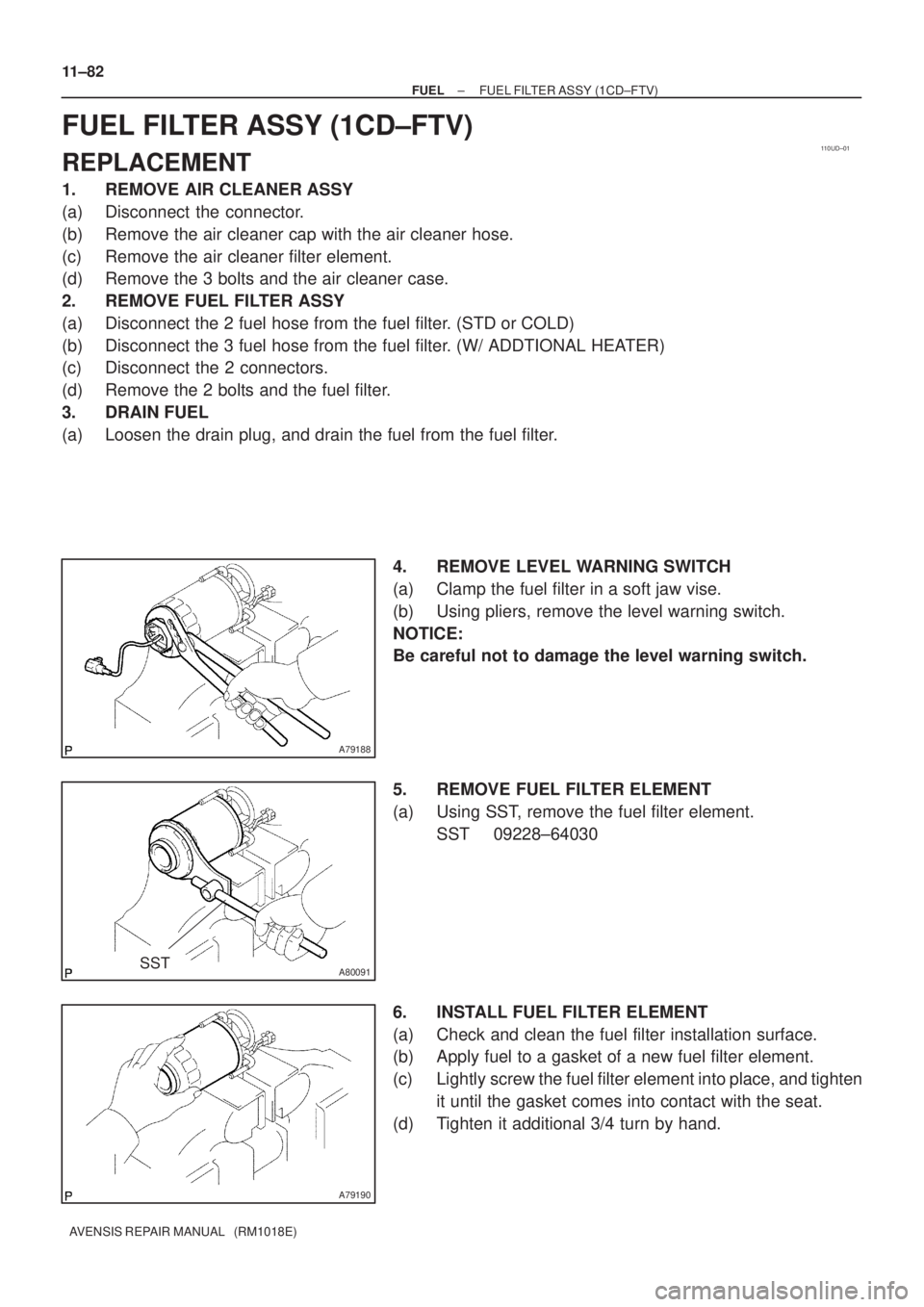
4. REMOVE LEVEL WARNING SWITCH
(a) Clamp the fuel filter in a soft jaw vise.
(b) Using pliers, remove the level warning switch.
NOTICE:
Be careful not to damage the level warning switch.
5. REMOVE FUEL FILTER ELEMENT
(a) Using SST, remove the fuel filter element.
SST 09228±64030
6. INSTALL FUEL FILTER ELEMENT
(a) Check and clean the fuel filter installation surface.
(b) Apply fuel to a gasket of a new fuel filter element.
(c) Lightly screw the fuel filter element into place, and tighten
it until the gasket comes into contact with the seat.
(d) Tighten it additional 3/4 turn by hand.
Page 1928 of 5135

110CX±02
A75346
A79038
E2S PR2 VCS
VCPR E2
Fuel pressure sensor
A79039Pressure discharge valve
A62162
Vacuum Switch Body
11±56
± FUELFUEL SYSTEM (1CD±FTV)
AVENSIS REPAIR MANUAL (RM1018E)
FUEL SYSTEM (1CD±FTV)
INSPECTION
1. INJECTION OR SUPPLY PUMP ASSY
(a) Resistance inspection.
(1) Using an ohmmeter, measure the resistance be-
tween the terminals.
Resistance: 1.5 to 2.3 � at 20�C (68�F)
2. INJECTOR ASSY
(a) Resistance inspection.
(1) Using an ohmmeter, measure the resistance between the terminals.
Resistance: 0.85 to 1.05 � at 20�C (68�F)
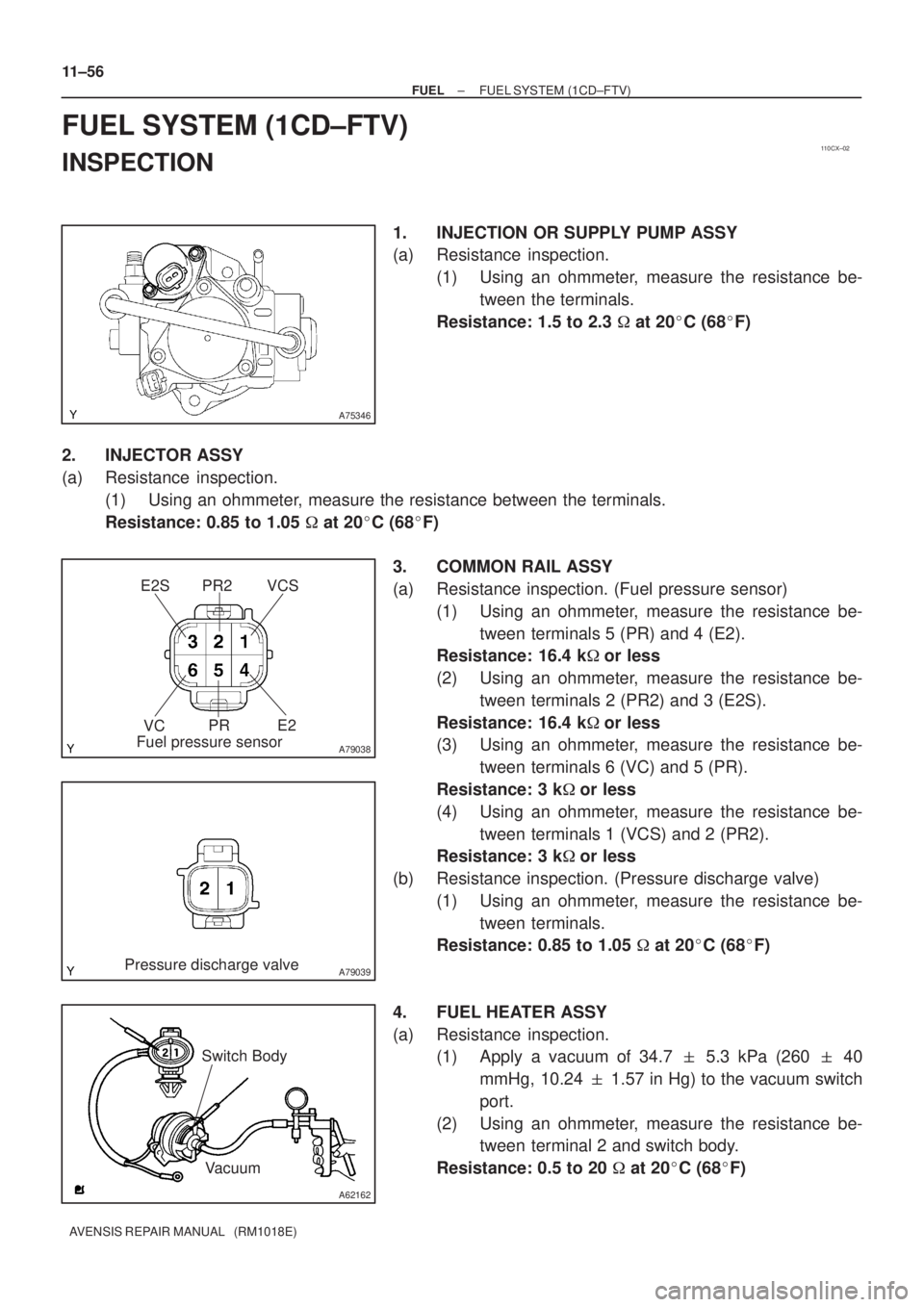
3. COMMON RAIL ASSY
(a) Resistance inspection. (Fuel pressure sensor)
(1) Using an ohmmeter, measure the resistance be-
tween terminals 5 (PR) and 4 (E2).
Resistance: 16.4 k�or less
(2) Using an ohmmeter, measure the resistance be-
tween terminals 2 (PR2) and 3 (E2S).
Resistance: 16.4 k�or less
(3) Using an ohmmeter, measure the resistance be-
tween terminals 6 (VC) and 5 (PR).
Resistance: 3 k�or less
(4) Using an ohmmeter, measure the resistance be-
tween terminals 1 (VCS) and 2 (PR2).
Resistance: 3 k�or less
(b) Resistance inspection. (Pressure discharge valve)
(1) Using an ohmmeter, measure the resistance be-
tween terminals.
Resistance: 0.85 to 1.05 � at 20�C (68�F)
4. FUEL HEATER ASSY
(a) Resistance inspection.
(1) Apply a vacuum of 34.7 � 5.3 kPa (260 � 40
mmHg, 10.24 � 1.57 in Hg) to the vacuum switch
port.
(2) Using an ohmmeter, measure the resistance be-
tween terminal 2 and switch body.
Resistance: 0.5 to 20 � at 20�C (68�F)
Page 1992 of 5135
1306Z±01
A79155
A80093
A79158
±
INTAKE TURBOCHARGER SUB±ASSY(1CD±FTV)
13±11
AVENSIS REPAIR MANUAL (RM1018E)
REPLACEMENT
1.REMOVE ENGINE UNDER COVER SUB±ASSY NO.1
2.DRAIN ENGINE COOLANT(See page 16±44)
3.REMOVE RADIATOR SUPPORT OPENING COVER
4.REMOVE ENGINE COVER NO.1
(a)Remove the 5 nuts and the engine cover.
5.REMOVE VACUUM RESERVOIR SUB±ASSY
(a)Disconnect the 2 vacuum hoses and the connector.
(b)Remove the 2 bolts and the vacuum reservoir.
6.REMOVE AIR CLEANER ASSY
(a)Disconnect the PCV hose and the connector.
(b)Remove the air cleaner cap with the air cleaner hose.
(c)Remove the air cleaner filter element.
(d)Remove the 3 bolts and the air cleaner case. 7.REMOVE INTERCOOLER AIR HOSE
(a)Remove the 3 bolts and nut, separate the air tube No.1.
(b)Loosen the hose clamp bolts and remove the air hoseNo.1.
8.REMOVE FUEL FILTER ASSY(See page 11±82) 9. SEPARATE HEATER PUMP ASSY (W/ COLD AREA)
(a) Remove the nut and disconnect the connector.
(b) Separate the heater pump.
Page 1993 of 5135
A79159
A79156
A79157
A79160
13±12
±
INTAKE TURBOCHARGER SUB±ASSY(1CD±FTV)
AVENSIS REPAIR MANUAL (RM1018E)
10.REMOVE HEATER BRACKET (W/ COLD AREA)
(a)Remove the bolt and the heater bracket.
11.REMOVE FLOOR PANEL BRACE FRONT(See page 15±10)
12.REMOVE EXHAUST PIPE ASSY FRONT(See page 15±10) 13. REMOVE EXHAUST PIPE ASSY (W/ COLD AREA)
(a) Remove the 2 nuts.
(b) Remove the 2 nuts and the exhaust pipe sub±assy.
14. REMOVE TURBO INSULATOR NO.2
(a) Remove the 4 bolts and the turbo insulator.
Page 1997 of 5135

������������A80106
A
A
B
B
A79163
13±16
±
INTAKE TURBOCHARGER SUB±ASSY(1CD±FTV)
AVENSIS REPAIR MANUAL (RM1018E)
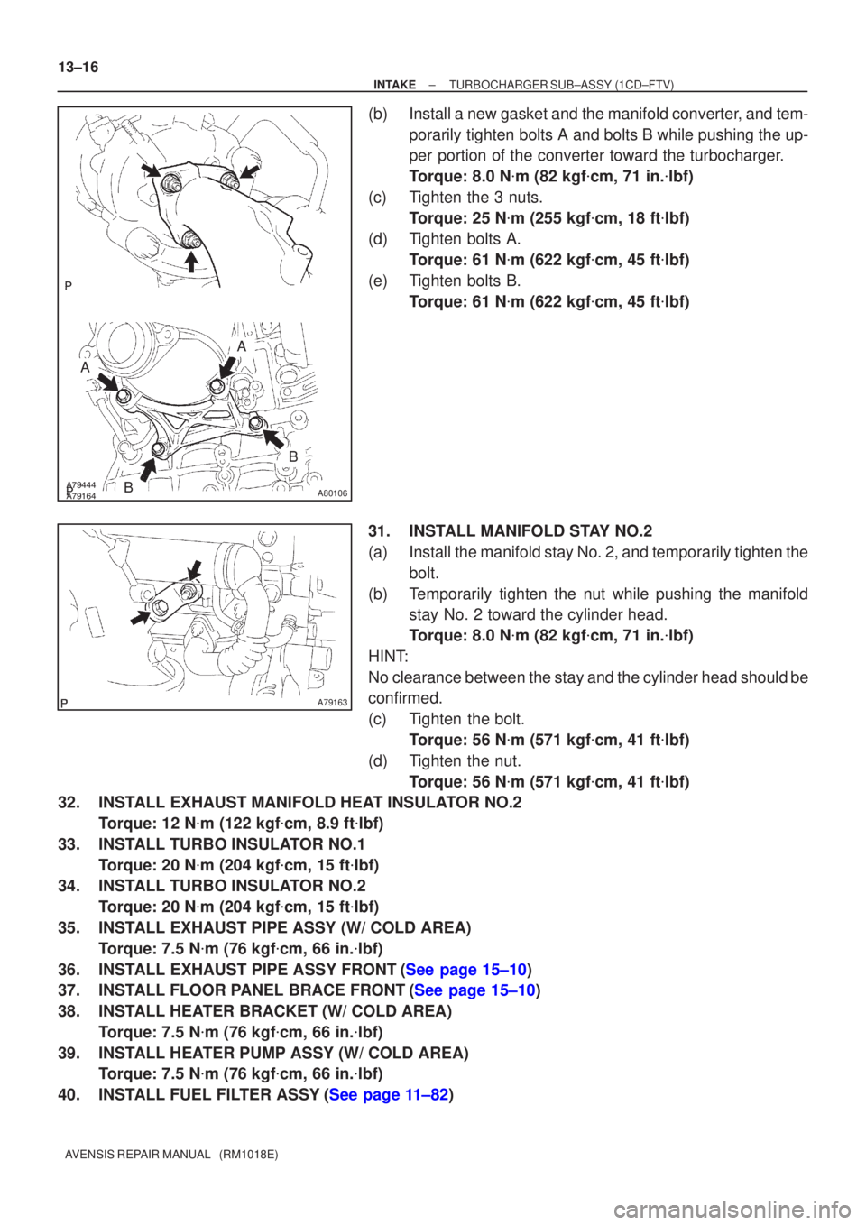
(b)Install a new gasket and the manifold converter, and tem- porarily tighten bolts A and bolts B while pushing the up-
per portion of the converter toward the turbocharger.
Torque: 8.0 N �m (82 kgf �cm, 71 in. �lbf)
(c)Tighten the 3 nuts. Torque: 25 N �m (255 kgf �cm, 18 ft �lbf)
(d)Tighten bolts A.
Torque: 61 N �m (622 kgf �cm, 45 ft �lbf)
(e)Tighten bolts B. Torque: 61 N �m (622 kgf �cm, 45 ft �lbf)
31.INSTALL MANIFOLD STAY NO.2
(a)Install the manifold stay No. 2, and temporarily tighten the bolt.
(b)Temporarily tighten the nut while pushing the manifold stay No. 2 toward the cylinder head.
Torque: 8.0 N �m (82 kgf �cm, 71 in. �lbf)
HINT:
No clearance between the stay and the cylinder head should be
confirmed.
(c)Tighten the bolt. Torque: 56 N �m (571 kgf �cm, 41 ft �lbf)
(d)Tighten the nut. Torque: 56 N �m (571 kgf �cm, 41 ft �lbf)
32.INSTALL EXHAUST MANIFOLD HEAT INSULATOR NO.2
Torque: 12 N �m (122 kgf �cm, 8.9 ft �lbf)
33.INSTALL TURBO INSULATOR NO.1 Torque: 20 N �m (204 kgf �cm, 15 ft �lbf)
34.INSTALL TURBO INSULATOR NO.2
Torque: 20 N �m (204 kgf �cm, 15 ft �lbf)
35.INSTALL EXHAUST PIPE ASSY (W/ COLD AREA) Torque: 7.5 N �m (76 kgf �cm, 66 in. �lbf)
36.INSTALL EXHAUST PIPE ASSY FRONT(See page 15±10)
37.INSTALL FLOOR PANEL BRACE FRONT(See page 15±10)
38. INSTALL HEATER BRACKET (W/ COLD AREA) Torque: 7.5 N �m (76 kgf �cm, 66 in. �lbf)
39. INSTALL HEATER PUMP ASSY (W/ COLD AREA) Torque: 7.5 N �m (76 kgf �cm, 66 in. �lbf)
40.INSTALL FUEL FILTER ASSY(See page 11±82)
Page 2000 of 5135
A79440
Union To Connector Tube Hose
Fuel Filter Assy Vacuum Reservoir Sub±assy
43 (440, 32)
43 (440, 32)
� Gasket
� GasketCompression Spring
Floor Panel Brace Front Exhaust Pipe Assy Front
Compression Spring
N´m (kgf´cm, ft´lbf)
: Specified torque
� Non±reusable part
Intercooler Air Hose
� Gasket
7.5 (76, 66 in.�lbf)
Exhaust Pipe Assy
30 (302, 22)
7.5 (76, 66 in.�lbf)
Heater Bracket
Heater Pump Assy25 (255, 18)
25 (255, 18)
7.5 (76, 66 in.�lbf)
18 (178, 13)
7.5 (76, 66 in.�lbf)
w/ Cold Area:
w/ Cold Area:
w/ Cold Area:
8.3 (85, 73 in.�lbf)
Air Tube No. 1
± INTAKETURBOCHARGER SUB±ASSY (1CD±FTV)
13±9
AVENSIS REPAIR MANUAL (RM1018E)
Page 2045 of 5135

A76724
A76714
A78461
1ZZ±FE
A78497
3ZZ±FE
±
ENGINE MECHANICAL PARTIAL ENGINE ASSY (1ZZ±FE/3ZZ±FE)
14±29
AVENSIS REPAIR MANUAL (RM1018E)
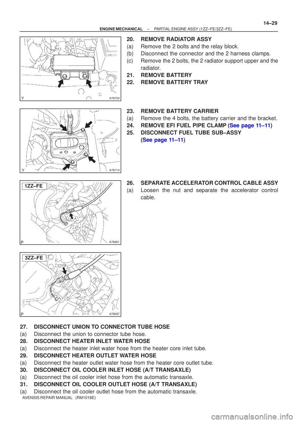
20. REMOVE RADIATOR ASSY
(a) Remove the 2 bolts and the relay block.
(b) Disconnect the connector and the 2 harness clamps.
(c) Remove the 2 bolts, the 2 radiator support upper and the
radiator.
21. REMOVE BATTERY
22. REMOVE BATTERY TRAY
23. REMOVE BATTERY CARRIER
(a) Remove the 4 bolts, the battery carrier and the bracket.
24.REMOVE EFI FUEL PIPE CLAMP(See page 11±11)
25. DISCONNECT FUEL TUBE SUB±ASSY (See page 11±11)
26. SEPARATE ACCELERATOR CONTROL CABLE ASSY
(a) Loosen the nut and separate the accelerator control cable.
27. DISCONNECT UNION TO CONNECTOR TUBE HOSE
(a) Disconnect the union to connector tube hose.
28. DISCONNECT HEATER INLET WATER HOSE
(a) Disconnect the heater inlet water hose from the heater core inlet tube.
29. DISCONNECT HEATER OUTLET WATER HOSE
(a) Disconnect the heater outlet water hose from the heater core outlet tube\
.
30. DISCONNECT OIL COOLER INLET HOSE (A/T TRANSAXLE)
(a) Disconnect the oil cooler inlet hose from the automatic transaxle.
31. DISCONNECT OIL COOLER OUTLET HOSE (A/T TRANSAXLE)
(a) Disconnect the oil cooler outlet hose from the automatic transaxle.
Page 2053 of 5135
A76722
A76723
A64033
A64034
A64034
± ENGINE MECHANICALPARTIAL ENGINE ASSY (1ZZ±FE/3ZZ±FE)
14±37
AVENSIS REPAIR MANUAL (RM1018E)
85. REMOVE EXHAUST MANIFOLD HEAT INSULATOR
NO.1
(a) Disconnect the heated oxygen sensor connector.
(b) Remove the 3 bolts and the nut, and then remove the ex-
haust manifold heat insulator.
86. REMOVE EXHAUST MANIFOLD
(a) Remove the 5 nuts, then remove the exhaust manifold
and the gasket.
87. REMOVE ENGINE COOLANT TEMPERATURE
SENSOR
(a) Using SST, remove the engine coolant temperature sen-
sor.
SST 09817±33190
88. REMOVE RADIO SETTING CONDENSER
(a) Remove the bolt and the condenser.
89. REMOVE WATER BY±PASS HOSE NO.2
90. REMOVE RADIATOR HOSE INLET
91. REMOVE HEATER INLET WATER HOSE
92. REPLACE PARTIAL ENGINE ASSY
93. INSTALL RADIO SETTING CONDENSER
(a) Install the condenser with the bolt.
Torque: 10 N�m (102 kgf�cm, 7 ft�lbf)