Page 1248 of 5135
I32396
E
IG INILL+
ILL±
P5
I37733
SWIN
1 2 3 4
5 6 7 8
P1
P5
05±1174
± DIAGNOSTICSCOMBUSTION TYPE POWER HEATER SYSTEM
AVENSIS REPAIR MANUAL (RM1018E)
1 INSPECT HETER SWITCH ASSY
(a) Check that the continuity when connecting the positive
tester lead (+) and the negative tester lead (±) to the fol-
lowing terminals.
Heater switch conditionConnectiong terminalsStandard Value
ONIG ± INContinuity
OFFIG ± INNo Continuity
ONIG ± EContinuity
OFFIG ± ENo Continuity
ONILL+ ± ILL±Continuity
OFFILL+ ± ILL±Continuity
NG REPLACE HETER SWITCH ASSY
OK
2 CHECK WIRE HARNESS(HETER SWITCH ASSY ± POWER HEATER ECU)
(a) Remove the A/C amplifier with connectors being con-
nected.
(b) Turn the ignition switch to ON.
(c) Measure the voltage between terminal IN of the heater
switch and SW of the power heater ECU.
Heater switch conditionStandard value
ON10 to 14 V
OFF0 V
NG REPAIR OR REPLACE WIRE HARNESS
OK
Page 1249 of 5135
I32395
IGP5
I32395
E
P5
±
DIAGNOSTICS COMBUSTION TYPE POWER HEATER SYSTEM
05±1175
AVENSIS REPAIR MANUAL (RM1018E)
3CHECK WIRE HARNESS(HETER SWITCH ASSY ± BATTERY)
(a)Check for an open and short circuit in harness and con-
nector between heater switch and battery
(See page 01±32).
NG REPAIR OR REPLACE WIRE HARNESS
OK
4 CHECK WIRE HARNESS(HETER SWITCH ASSY ± BODY GROUND)
(a) Check for an open circuit in henees and connector be- tween heater swith and body ground
(See page 01±32).
NG REPAIR OR REPLACE WIRE HARNESS
OK
PROCEED TO NEXT CIRCUIT INSPECTION SHOWN IN PROBLEM SYMPTOMS TABLE
Page 1425 of 5135
05±1404
± DIAGNOSTICSAUDIO SYSTEM
AVENSIS REPAIR MANUAL (RM1018E)
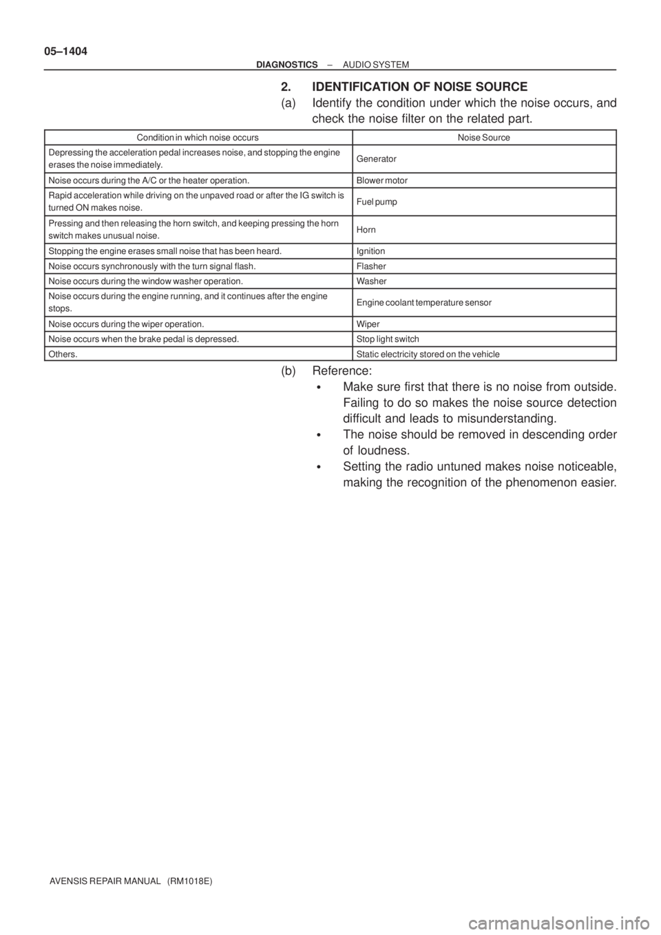
2. IDENTIFICATION OF NOISE SOURCE
(a) Identify the condition under which the noise occurs, and
check the noise filter on the related part.
Condition in which noise occursNoise Source
Depressing the acceleration pedal increases noise, and stopping the engine
erases the noise immediately.Generator
Noise occurs during the A/C or the heater operation.Blower motor
Rapid acceleration while driving on the unpaved road or after the IG switch is
turned ON makes noise.Fuel pump
Pressing and then releasing the horn switch, and keeping pressing the horn
switch makes unusual noise.Horn
Stopping the engine erases small noise that has been heard.Ignition
Noise occurs synchronously with the turn signal flash.Flasher
Noise occurs during the window washer operation.Washer
Noise occurs during the engine running, and it continues after the engine
stops.Engine coolant temperature sensor
Noise occurs during the wiper operation.Wiper
Noise occurs when the brake pedal is depressed.Stop light switch
Others.Static electricity stored on the vehicle
(b) Reference:
�Make sure first that there is no noise from outside.
Failing to do so makes the noise source detection
difficult and leads to misunderstanding.
�The noise should be removed in descending order
of loudness.
�Setting the radio untuned makes noise noticeable,
making the recognition of the phenomenon easier.
Page 1443 of 5135
H40065
IG2
E2 E1
05±1384
±
DIAGNOSTICS SUPPLEMENTAL RESTRAINT SYSTEM
AVENSIS REPAIR MANUAL (RM1018E)
INSPECTION PROCEDURE
1PREPARE FOR INSPECTION
(a)Turn the ignition switch to the LOCK position.
(b)Disconnect the negative (±) terminal cable from the battery, and wait for at least 90 seconds.
(c)Disconnect the connectors of the airbag sensor assy center (See page 60±62).
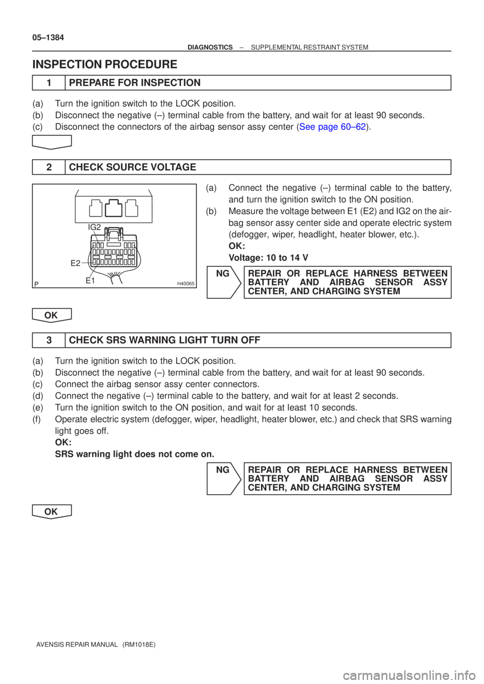
2 CHECK SOURCE VOLTAGE
(a) Connect the negative (±) terminal cable to the battery, and turn the ignition switch to the ON position.
(b) Measure the voltage between E1 (E2) and IG2 on the air- bag sensor assy center side and operate electric system
(defogger, wiper, headlight, heater blower, etc.).
OK:
Voltage: 10 to 14 V
NG REPAIR OR REPLACE HARNESS BETWEEN BATTERY AND AIRBAG SENSOR ASSY
CENTER, AND CHARGING SYSTEM
OK
3 CHECK SRS WARNING LIGHT TURN OFF
(a) Turn the ignition switch to the LOCK position.
(b) Disconnect the negative (±) terminal cable from the battery, and wait for at least 90 seconds.
(c) Connect the airbag sensor assy center connectors.
(d) Connect the negative (±) terminal cable to the battery, and wait for at least 2 seconds.
(e) Turn the ignition switch to the ON position, and wait for at least 10 sec\
onds.
(f) Operate electric system (defogger, wiper, headlight, heater blower, etc.) and check that SRS warning light goes off.
OK:
SRS warning light does not come on.
NG REPAIR OR REPLACE HARNESS BETWEENBATTERY AND AIRBAG SENSOR ASSY
CENTER, AND CHARGING SYSTEM
OK
Page 1475 of 5135
± DIAGNOSTICSAUDIO SYSTEM
05±1419
AVENSIS REPAIR MANUAL (RM1018E)
NOISE OCCURS
INSPECTION PROCEDURE
1 CHECK OF SPEAKER INSTALLATION
(a) Check the speaker installation condition.
(1) Check that each speaker is securely installed.
Standard: Malfunction disappears.
HINT:
The radio is equipped with the noise prevention system that works against only the excessively large noise,
thereby excessively large noise do not occur in the radio. If large noise occurs, check whether or not the earth
on the antenna installation part and the proper noise±prevention equipment are all installed, and whether
or not the improper wiring is held.
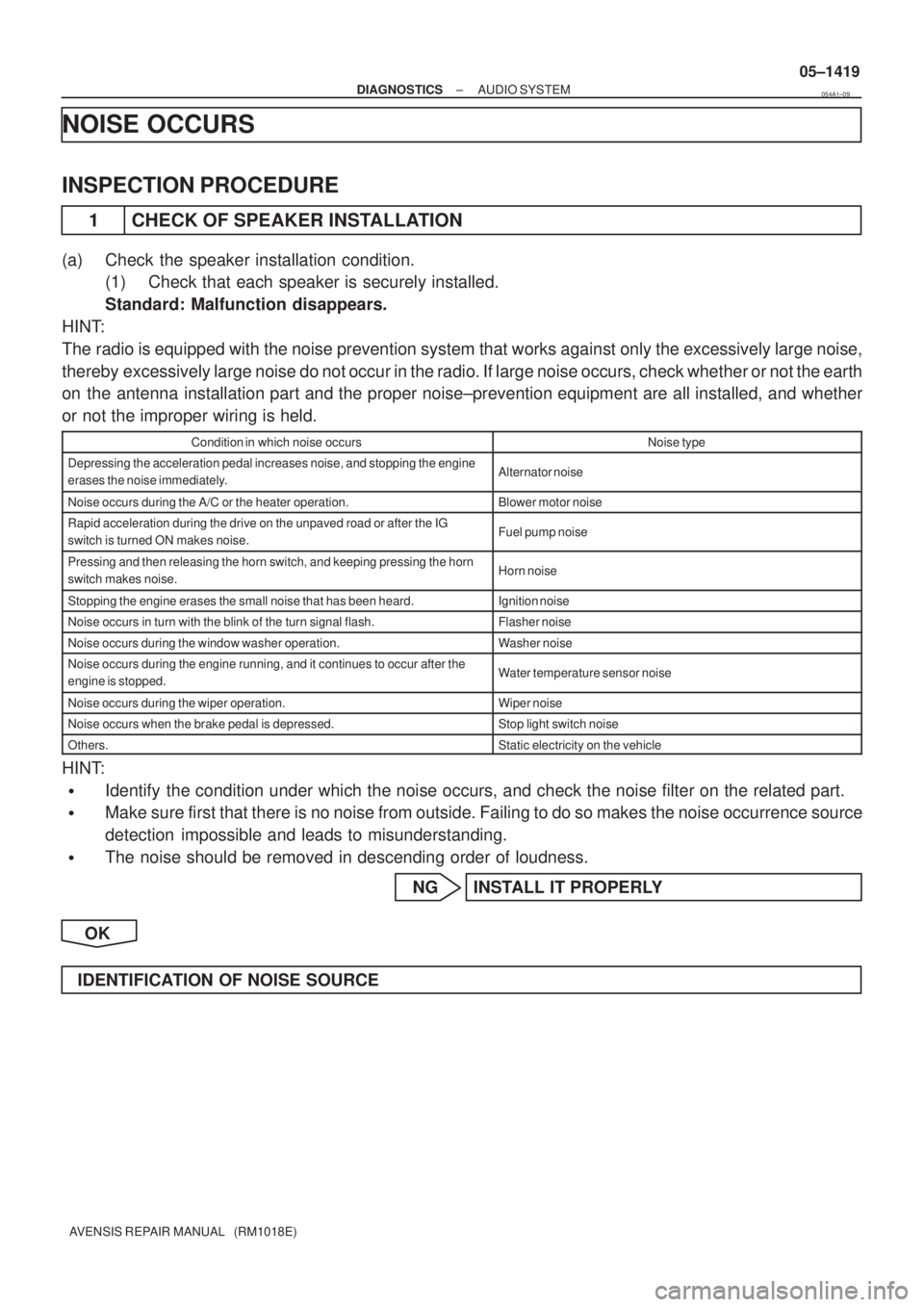
Condition in which noise occursNoise type
Depressing the acceleration pedal increases noise, and stopping the engine
erases the noise immediately.Alternator noise
Noise occurs during the A/C or the heater operation.Blower motor noise
Rapid acceleration during the drive on the unpaved road or after the IG
switch is turned ON makes noise.Fuel pump noise
Pressing and then releasing the horn switch, and keeping pressing the horn
switch makes noise.Horn noise
Stopping the engine erases the small noise that has been heard.Ignition noise
Noise occurs in turn with the blink of the turn signal flash.Flasher noise
Noise occurs during the window washer operation.Washer noise
Noise occurs during the engine running, and it continues to occur after the
engine is stopped.Water temperature sensor noise
Noise occurs during the wiper operation.Wiper noise
Noise occurs when the brake pedal is depressed.Stop light switch noise
Others.Static electricity on the vehicle
HINT:
�Identify the condition under which the noise occurs, and check the noise filter on the related part.
�Make sure first that there is no noise from outside. Failing to do so makes the noise occurrence source
detection impossible and leads to misunderstanding.
�The noise should be removed in descending order of loudness.
NG INSTALL IT PROPERLY
OK
IDENTIFICATION OF NOISE SOURCE
054A1±09
Page 1832 of 5135
100FL±01
A77917
A77918
(a)
(b)
A77919
10±34
±
ENGINE CONTROL SYSTEM KNOCK SENSOR(1AZ±FE)
AVENSIS REPAIR MANUAL (RM1018E)
REPLACEMENT
1.DISCHARGE FUEL SYSTEM PRESSURE (See page 11±15)
2.REMOVE ENGINE ROOM COVER SIDE (See page 10±26)
3.REMOVE RADIATOR SUPPORT OPENING COVER (See page 10±26)
4.ENGINE COOLANT (See page 16±19)
5.REMOVE ENGINE COVER SUB±ASSY NO.1 (See page 10±26)
6.REMOVE AIR CLEANER CAP SUB±ASSY (See page 10±26)
7.SEPARATE ACCELERATOR CONTROL CABLE ASSY (See page 10±26)
8.REMOVE THROTTLE BODY ASSY (See page 10±26)
9.DISCONNECT FUEL TUBE SUB±ASSY (See page 11±26) SST 09268±21010
10.REMOVE FUEL DELIVERY PIPE SUB±ASSY (See page 11±26)
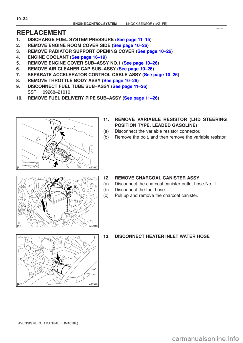
11. REMOVE VARIABLE RESISTOR (LHD STEERINGPOSITION TYPE, LEADED GASOLINE)
(a) Disconnect the variable resistor connector.
(b) Remove the bolt, and then remove the variable resistor.
12. REMOVE CHARCOAL CANISTER ASSY
(a) Disconnect the charcoal canister outlet hose No. 1.
(b) Disconnect the fuel hose.
(c) Pull up and remove the charcoal canister.
13. DISCONNECT HEATER INLET WATER HOSE
Page 1834 of 5135
10±36
±
ENGINE CONTROL SYSTEM KNOCK SENSOR(1AZ±FE)
AVENSIS REPAIR MANUAL (RM1018E)
18.INSTALL INTAKE MANIFOLD INSULATOR NO.1
19.INSTALL INTAKE MANIFOLD
(a)Install a new gasket to the intake manifold.
(b)Install the intake manifold with the 5 bolts and 2 nuts. Torque: 30 N �m (306 kgf �cm, 22 ft �lbf)
(c)Install the wire harness clamp.
(d)Connect the union to connector tube hose.
20.CONNECT HEATER INLET WATER HOSE
21.INSTALL CHARCOAL CANISTER ASSY
22.INSTALL VARIABLE RESISTOR (LHD STEERING POSITION TYPE, LEADED GASOLINE) Torque: 5.0 N �m (51 kgf �cm, 44 in. �lbf)
23.INSTALL FUEL DELIVERY PIPE SUB±ASSY (See page 11±26)
24.CONNECT FUEL TUBE SUB±ASSY (See page 11±26)
25.INSTALL THROTTLE BODY ASSY (See page 10±26)
26.INSTALL ACCELERATOR CONTROL CABLE ASSY (See page 10±26)
27. INSTALL AIR CLEANER CAP SUB±ASSY
28.ADD ENGINE COOLANT (See page 16±19)
29.CHECK FOR ENGINE COOLANT LEAKS (See page 16±13)
30.CHECK FOR FUEL LEAKS (See page 11±19)
31.INSTALL ENGINE COVER SUB±ASSY NO.1 (See page 10±26)
32. INSTALL ENGINE ROOM COVER SIDE
33. INSTALL RADIATOR SUPPORT OPENING COVER
Page 1838 of 5135
A77916� Non±reusable part
N´m (kgf´cm, ft´lbf) : Specified torque
30 (306, 22)
Heater Inlet Water Hose
Knock Sensor
ConnectorKnock Sensor
20 (204, 15)
Intake Manifold Insulator No. 1
� Intake Manifold
to Head Gasket No. 1
Intake Manifold
LHD Steering Position Type,
Leaded Gasoline:
Variable Resister
5.0 (51, 44 in.�lbf)
Charcoal Canister Assy
Variable Resister Connector
Charcoal Canister
Outlet Hose No. 1
Fuel Hose
x5
± ENGINE CONTROL SYSTEMKNOCK SENSOR (1AZ±FE)
10±33
AVENSIS REPAIR MANUAL (RM1018E)