Page 654 of 5135
A81483
Suction Control Valve
Opening Small
Operation DiagramPlunger
Top±Dead CenterPlunger
Bottom±Dead CenterPumping
Starting Point
Cam
Stroke: Fuel Pumping Volume
Check Valve
Small
Suction
Area(1)
(2)(3)
(1) (2) (3) Suction
Control
Valve
A81484
Pumping
Starting Point
Large
Suction
Area
(1)
(2)(3) Cam
Stroke
(1) (2) (3): Fuel Pumping Volume Suction Control Valve
Opening Large
Operation Diagram
Suction
Control
Valve
± DIAGNOSTICSECD SYSTEM (1CD±FTV)
05±521
AVENSIS REPAIR MANUAL (RM1018E)
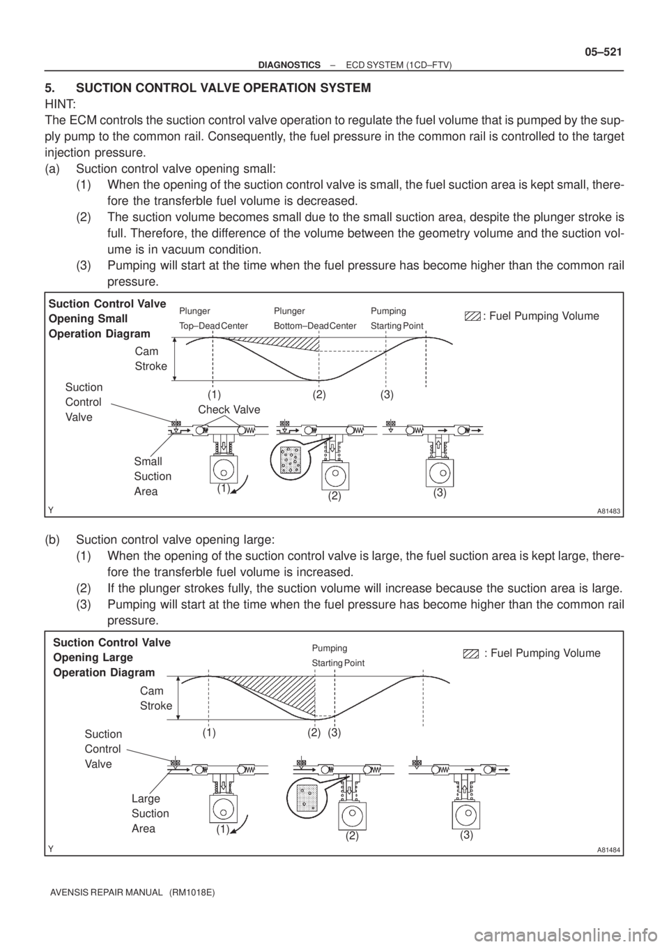
5. SUCTION CONTROL VALVE OPERATION SYSTEM
HINT:
The ECM controls the suction control valve operation to regulate the fuel volume that is pumped by the sup-
ply pump to the common rail. Consequently, the fuel pressure in the common rail is controlled to the target
injection pressure.
(a) Suction control valve opening small:
(1) When the opening of the suction control valve is small, the fuel suction area is kept small, there-
fore the transferble fuel volume is decreased.
(2) The suction volume becomes small due to the small suction area, despite the plunger stroke is
full. Therefore, the difference of the volume between the geometry volume and the suction vol-
ume is in vacuum condition.
(3) Pumping will start at the time when the fuel pressure has become higher than the common rail
pressure.
(b) Suction control valve opening large:
(1) When the opening of the suction control valve is large, the fuel suction area is kept large, there-
fore the transferble fuel volume is increased.
(2) If the plunger strokes fully, the suction volume will increase because the suction area is large.
(3) Pumping will start at the time when the fuel pressure has become higher than the common rail
pressure.
Page 658 of 5135
A81000
ECM
THW E2
19
E13
28
E13
L
W
1 2
E2
Engine Coolant Temp. Sensor
5V
R
BR
B±W
2
EC1
1
EC1
05±594
±
DIAGNOSTICS ECD SYSTEM(1CD±FTV)
AVENSIS REPAIR MANUAL (RM1018E)
WIRING DIAGRAM
INSPECTION PROCEDURE
HINT:
�If different DTCs related to different systems that have terminal E2 as the ground terminal are output
simultaneously, terminal E2 may be open.
�Read freeze frame data using \f���� ����\b�\f��\f�
. Freeze frame data records the engine conditions
when a malfunction is detected. When troubleshooting, it is useful for d\
etermining whether the vehicle
was running or stopped, the engine was warmed up or not, etc. at the time o\
f the malfunction.
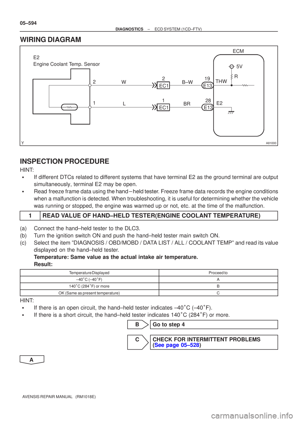
1READ VALUE OF HAND±HELD TESTER(ENGINE COOLANT TEMPERATURE)
(a)Connect the hand±held tester to the DLC3.
(b)Turn the ignition switch ON and push the hand±held tester main switch \
ON.
(c)Select the item ºDIAGNOSIS / OBD/MOBD / DATA LIST / ALL / COOLANT TEMPº and read its value displayed on the hand±held tester.
Temperature: Same value as the actual intake air temperature.
Result:
Temperature DisplayedProceed to
±40
C (±40
�)A
140
C (284
�) or moreB
OK (Same as present temperature)C
HINT:
�If there is an open circuit, the hand±held tester indicates ±40
C (±40
F).
�If there is a short circuit, the hand±held tester indicates 140
C (284
F) or more.
BGo to step 4
CCHECK FOR INTERMITTENT PROBLEMS (See page 05±528)
A
Page 662 of 5135
A72925
BR
G±R
28
31
E13 THA
E2 ECM
1 2
A6
Intake Air Temperature Sensor
(Built in Mass Air Flow Meter)
E135V
R
THA
E2
05±590
±
DIAGNOSTICS ECD SYSTEM(1CD±FTV)
AVENSIS REPAIR MANUAL (RM1018E)
WIRING DIAGRAM
INSPECTION PROCEDURE
HINT:
�If different DTCs related to different systems that have terminal E2 as the ground terminal are output
simultaneously, terminal E2 may be open.
�Read freeze frame data using
\b�\b�
��\b� �
�\f
��� Freeze frame data records the engine conditions
when a malfunction is detected. When troubleshooting, it is useful for d\
etermining whether the vehicle
was running or stopped, the engine was warmed up or not, etc. at the time o\
f the malfunction.
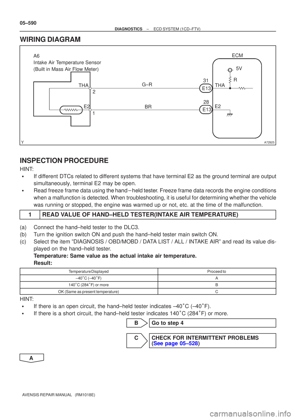
1READ VALUE OF HAND±HELD TESTER(INTAKE AIR TEMPERATURE)
(a)Connect the hand±held tester to the DLC3.
(b)Turn the ignition switch ON and push the hand±held tester main switch \
ON.
(c)Select the item ºDIAGNOSIS / OBD/MOBD / DATA LIST / ALL / INTAKE AIRº and read its value dis- played on the hand±held tester.
Temperature: Same value as the actual intake air temperature.
Result:
Temperature DisplayedProceed to
±40�C (±40 ��)A
140 �C (284 ��) or moreB
OK (Same as present temperature)C
HINT:
�If there is an open circuit, the hand±held tester indicates ±40 �C (±40 �F).
�If there is a short circuit, the hand±held tester indicates 140 �C (284 �F) or more.
BGo to step 4
CCHECK FOR INTERMITTENT PROBLEMS (See page 05±528)
A
Page 667 of 5135
A81002
5V
W±R E13
3
2
1
VC
PIM
E2
T5
Manifold Absolute
Pressure Sensor
ECM
E2
PIM
VC
28 28 18
R±W
BR E12
E13
±
DIAGNOSTICS ECD SYSTEM(1CD±FTV)
05±585
AVENSIS REPAIR MANUAL (RM1018E)
WIRING DIAGRAM
INSPECTION PROCEDURE
HINT:
�If different DTCs related to different systems that have terminal E2 as the ground terminal are output
simultaneously, terminal E2 may be open.
�Read freeze frame data using \f���� ����\b�\f��\f�
� Freeze frame data records the engine conditions
when a malfunction is detected. When troubleshooting, it is useful for d\
etermining whether the vehicle
was running or stopped, the engine was warmed up or not, etc. at the time o\
f the malfunction.
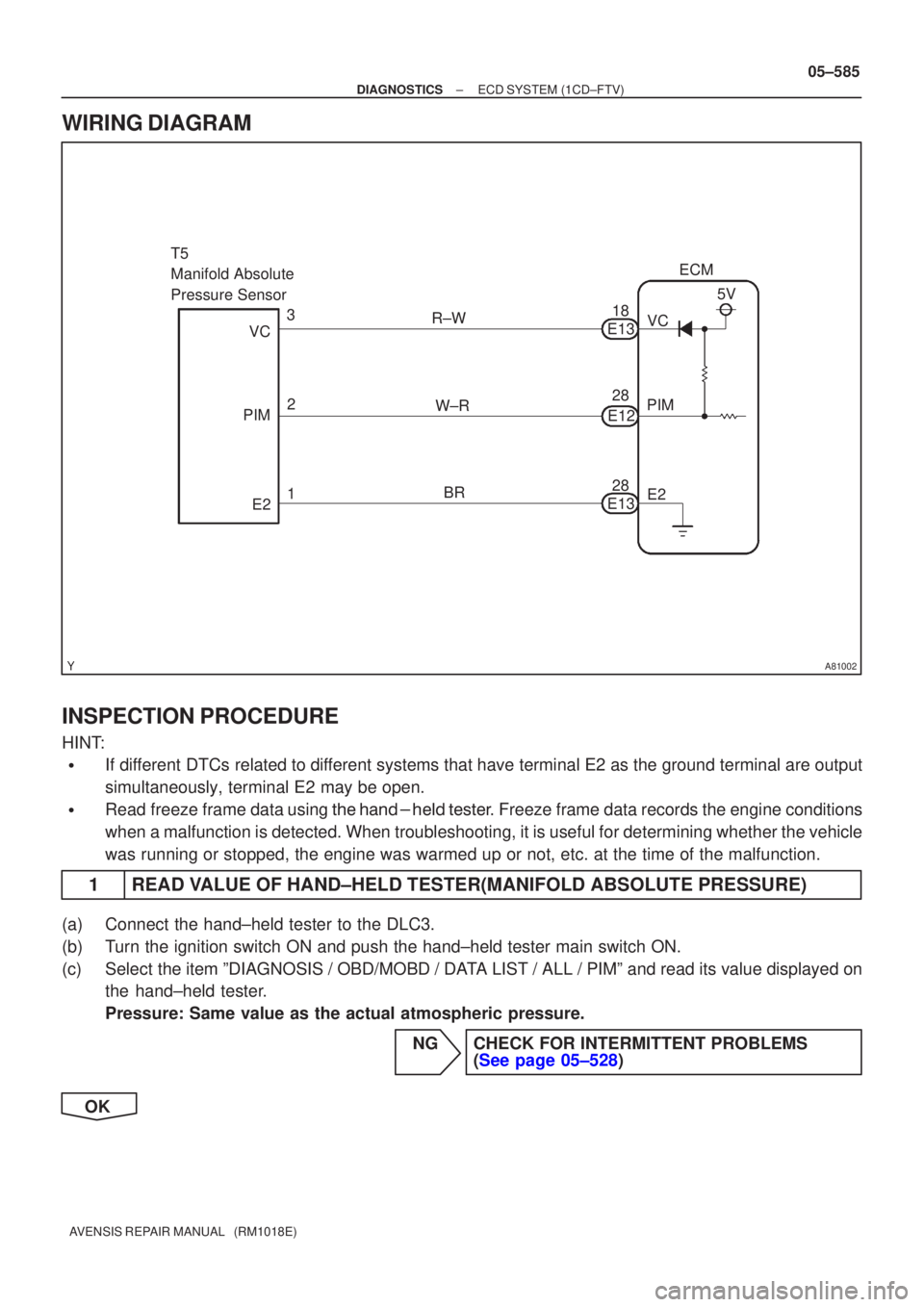
1READ VALUE OF HAND±HELD TESTER(MANIFOLD ABSOLUTE PRESSURE)
(a)Connect the hand±held tester to the DLC3.
(b)Turn the ignition switch ON and push the hand±held tester main switch \
ON.
(c)Select the item ºDIAGNOSIS / OBD/MOBD / DATA LIST / ALL / PIMº and read its value displayed on the hand±held tester.
Pressure: Same value as the actual atmospheric pressure.
NGCHECK FOR INTERMITTENT PROBLEMS(See page 05±528)
OK
Page 671 of 5135
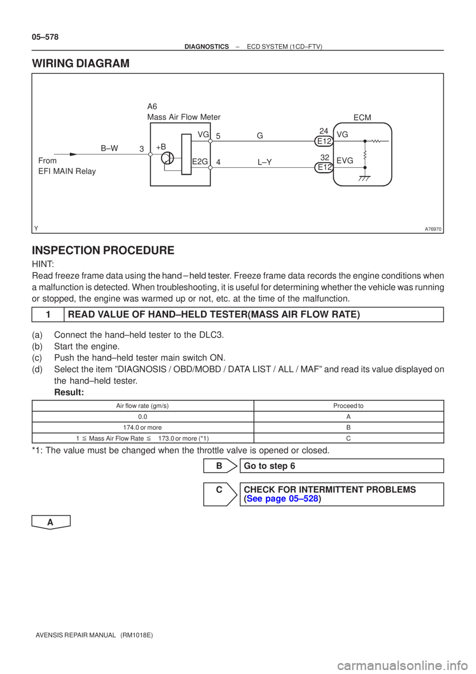
A76970
L±Y
3
4
A6
Mass Air Flow Meter
ECM
5 G
+B VG
E2G
From
EFI MAIN Relay B±W
VG
E12
EVG
24
32
E12
05±578
±
DIAGNOSTICS ECD SYSTEM(1CD±FTV)
AVENSIS REPAIR MANUAL (RM1018E)
WIRING DIAGRAM
INSPECTION PROCEDURE
HINT:
Read freeze frame data using �����\b��������
�� . Freeze frame data records the engine conditions when
a malfunction is detected. When troubleshooting, it is useful for determi\
ning whether the vehicle was running
or stopped, the engine was warmed up or not, etc. at the time of the malfu\
nction.
1READ VALUE OF HAND±HELD TESTER(MASS AIR FLOW RATE)
(a)Connect the hand±held tester to the DLC3.
(b)Start the engine.
(c)Push the hand±held tester main switch ON.
(d)Select the item ºDIAGNOSIS / OBD/MOBD / DATA LIST / ALL / MAFº and read its value displayed on the hand±held tester.
Result:
Air flow rate (gm/s)Proceed to
0.0A
174.0 or moreB
1 � Mass Air Flow Rate �173.0 or more (*1)C
*1: The value must be changed when the throttle valve is opened or closed.
BGo to step 6
CCHECK FOR INTERMITTENT PROBLEMS (See page 05±528)
A
Page 677 of 5135
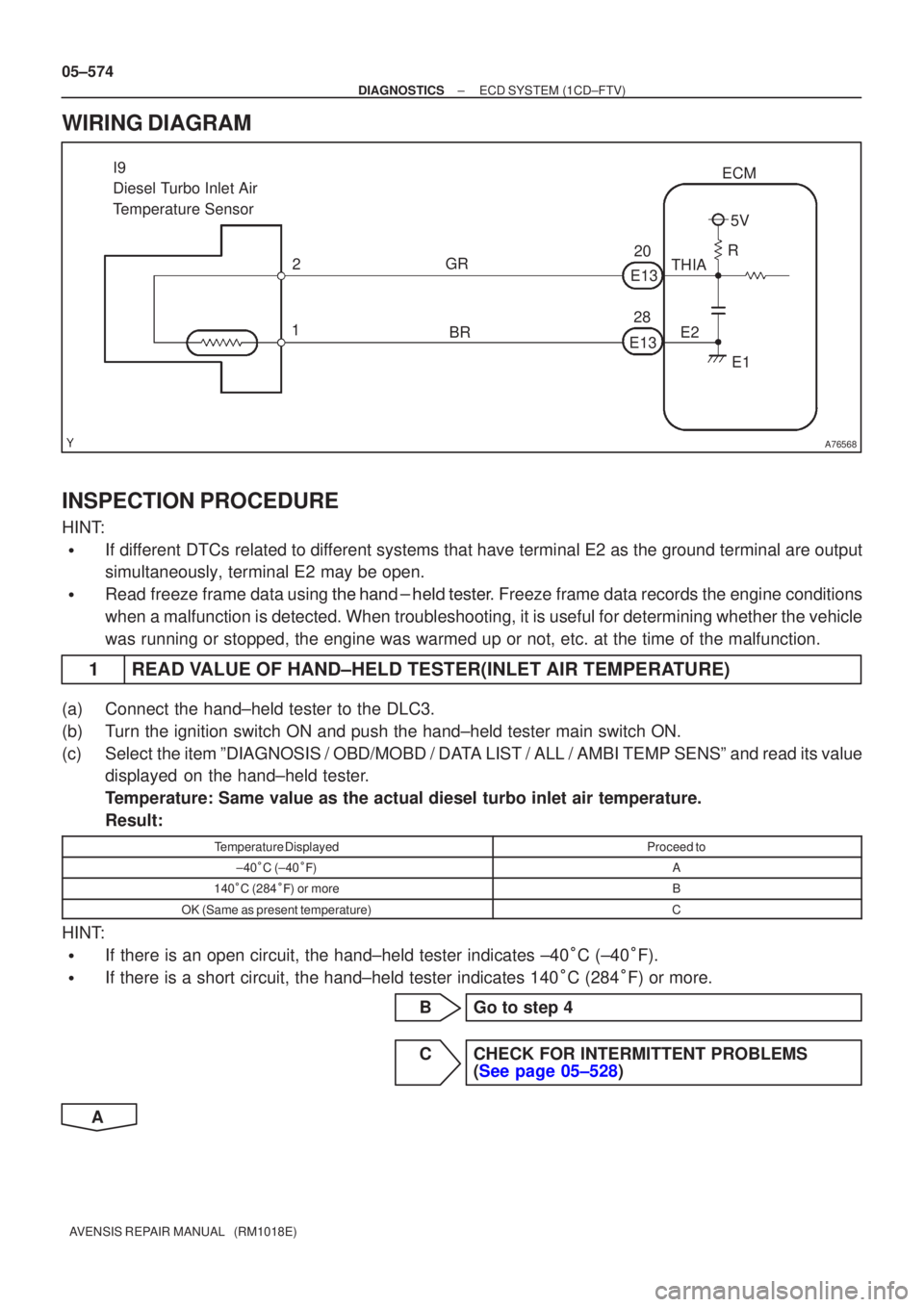
A76568
I9
Diesel Turbo Inlet Air
Temperature Sensor2
1 GR
E2E1
THIA
R5V
ECM
E13 E13
20
28
BR
05±574
±
DIAGNOSTICS ECD SYSTEM(1CD±FTV)
AVENSIS REPAIR MANUAL (RM1018E)
WIRING DIAGRAM
INSPECTION PROCEDURE
HINT:
�If different DTCs related to different systems that have terminal E2 as the ground terminal are output
simultaneously, terminal E2 may be open.
�Read freeze frame data using
\b�\b�
��\b� �
�\f
��� Freeze frame data records the engine conditions
when a malfunction is detected. When troubleshooting, it is useful for d\
etermining whether the vehicle
was running or stopped, the engine was warmed up or not, etc. at the time o\
f the malfunction.
1READ VALUE OF HAND±HELD TESTER(INLET AIR TEMPERATURE)
(a)Connect the hand±held tester to the DLC3.
(b)Turn the ignition switch ON and push the hand±held tester main switch \
ON.
(c)Select the item ºDIAGNOSIS / OBD/MOBD / DATA LIST / ALL / AMBI TEMP SENSº and read its value displayed on the hand±held tester.
Temperature: Same value as the actual diesel turbo inlet air temperature.\
Result:
Temperature DisplayedProceed to
±40�C (±40 ��)A
140 �C (284 ��) or moreB
OK (Same as present temperature)C
HINT:
�If there is an open circuit, the hand±held tester indicates ±40 �C (±40 �F).
�If there is a short circuit, the hand±held tester indicates 140 �C (284 �F) or more.
BGo to step 4
CCHECK FOR INTERMITTENT PROBLEMS (See page 05±528)
A
Page 687 of 5135

A80998
F16
Fuel Pressure Sensor
5
P
PCR1ECM
E1326 5
EB1
2
P±B
PCR2
E1333 2
EB1
1
R±W
VCS
E122 1
EB1
6
R±W
VC
E1318 6
EB1
3
BR
E2S
E121 3
EB1
4
BR
E2
E1328 4
EB1 PR
PR2P
P±B
R±W
R±W
BR
BR VC
E2S VCS
E2
± DIAGNOSTICSECD SYSTEM (1CD±FTV)
05±561
AVENSIS REPAIR MANUAL (RM1018E)
WIRING DIAGRAM
INSPECTION PROCEDURE
HINT:
�After completing repair, confirm P0087 is not set again.
�If different DTCs related to different systems that have terminal E2 as the ground terminal are output
simultaneously, terminal E2 may be open.
�Read freeze frame data using the hand±held tester. Freeze frame data records the engine conditions
when a malfunction is detected. When troubleshooting, it is useful for determining whether the vehicle
was running or stopped, the engine was warmed up or not, etc. at the time of the malfunction.
1 READ VALUE OF HAND±HELD TESTER(FUEL PRESSURE)
(a) Connect the hand±held tester to the DLC3.
(b) Turn the ignition switch ON and push the hand±held tester main switch ON.
(c) Start the engine.
(d) Select the item ºDIAGNOSIS / OBD/MOBD / DATA LIST / ALL / COMN RAIL PRESSº.
(e) Check that internal fuel pressure of the common rail is within specification below.
Reference:
Engine SpeedFuel Pressure (MPa)
IdlingApprox. 30 to 40
Running the engine at 2,500 rpm (No engine load)Approx. 50 to 100
NG Go to step 3
OK
Page 689 of 5135
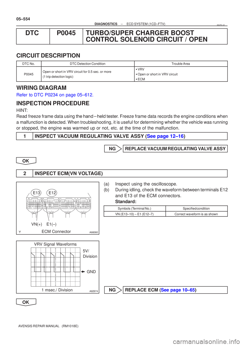
A66060
E13
ECM ConnectorE12
VN(+)E1(±)
A82974
VRV Signal Waveforms
GND
5V/
Division
1 msec./ Division
05±554
±
DIAGNOSTICS ECD SYSTEM(1CD±FTV)
AVENSIS REPAIR MANUAL (RM1018E)
DTCP0045TURBO/SUPER CHARGER BOOST CONTROL SOLENOID CIRCUIT / OPEN
CIRCUIT DESCRIPTION
DTC No.DTC Detection ConditionTrouble Area
P0045Open or short in VRV circuit for 0.5sec. or more
(1 trip detection logic)�VRV
� Open or short in VRV circuit
� ECM
WIRING DIAGRAM
Refer to DTC P0234 on page 05±612.
INSPECTION PROCEDURE
HINT:
Read freeze frame data using �����\b��������
�� . Freeze frame data records the engine conditions when
a malfunction is detected. When troubleshooting, it is useful for determi\
ning whether the vehicle was running
or stopped, the engine was warmed up or not, etc. at the time of the malfu\
nction.
1INSPECT VACUUM REGULATING VALVE ASSY (See page 12±16)
NGREPLACE VACUUM REGULATING VALVE ASSY
OK
2INSPECT ECM(VN VOLTAGE)
(a)Inspect using the oscilloscope.
(b)During idling, check the waveform between terminals E12 and E13 of the ECM connectors.
Standard:
Symbols (Terminal No.)Specified condition
VN (E13±10) ± E1 (E12±7)Correct waveform is as shown
NGREPLACE ECM (See page 10±65)
OK
05CPC±01