Page 775 of 5135
A81010
B±Y
12
E10
2 Engine Room R/B No. 1
IE37
BATT
Battery BB
33
FL MAIN1
1A
1 Engine Room R/B No. 3
EFI
IO17
B±YECM
(LHD) (RHD)
± DIAGNOSTICSECD SYSTEM (1CD±FTV)
05±647
AVENSIS REPAIR MANUAL (RM1018E)
DTC P0560 SYSTEM VOLTAGE
CIRCUIT DESCRIPTION
While the ignition switch is OFF, the battery positive voltage is supplied to terminal BATT of the ECM for the
DTCs memory and air±fuel ratio adaptive control value memory, etc.
DTC No.DTC Detection ConditionTrouble Area
P0560Open in back±up power source circuit (1 trip detection logic).�Open in back±up power source circuit
�ECM
HINT:
If DTC P0560 appears, the ECM does not store other DTC.
WIRING DIAGRAM
INSPECTION PROCEDURE
HINT:
Read freeze frame data using ��� ��������� ��
�� . Freeze frame data records the engine conditions when
a malfunction is detected. When troubleshooting, it is useful for determining whether the vehicle was running
or stopped, the engine was warmed up or not, etc. at the time of the malfunction.
05CPX±01
Page 779 of 5135
F45133
1 2 33ALT Engine Room R/B No.3
B (*2) W (*2) B±G (*1)
ALT 1
4D 1
1
4B Engine Room J/B No.4 ED1
BatteryFL MAIN
*1: Gasoline
*2: 1CD±FTV
*3: LHD
*4: RHD B±G (*1)
B±L (*2)
1
5918
1 53
2
1
DH DA DB DN
DH
AM1 ECU±IG IG Relay
W±BS21
GND1 GND2
S24
W±BW±B
EA W±B
IJ B (*2) B±G (*1)G±Y R±W
W±B
G±R G±Y G±YR±W R±W
R±W J/C
J10 J20 J10 J20 S2 IG1GC GC 1822
IE1Skid Control ECU
with Actuator
(*3) (*4) (*3) (*4)
I13
Ignition SW
1 3
B±L (*2)
Driver Side J/B
± DIAGNOSTICSABS WITH EBD SYSTEM
05±727
AVENSIS REPAIR MANUAL (RM1018E)
WIRING DIAGRAM
Page 783 of 5135
F45132
Battery FL MAINSkid Control ECU
with Actuator
B±G (*1) R (*1)
1 ALT ABS Engine Room R/B No.4 & Engine Room J/B No.4
1
4B
W±BS2
S21 3
+BS
12
1 2
GND1 GND2
S24
W±BW±B
*1: Gasoline
*2: 1CD±FTVEA4
R (*2)
W (*2)
2 12 33 11B1ABS ALT Engine Room R/B No.3Engine Room R/B No.1 &
Engine Room J/B No.1
B (*2)
B±G (*1) 05±722
± DIAGNOSTICSABS WITH EBD SYSTEM
AVENSIS REPAIR MANUAL (RM1018E)
DTC C0278/11 OPEN OR SHORT CIRCUT IN ABS
SOLENOID RELAY
CIRCUIT DESCRIPTION
This relay supplies power to each ABS solenoid. After the ignition switch is turned ON, if the initial check is
OK, the relay goes on.
DTC No.DTC Detecting ConditionTrouble Area
C0278/11
Detection of any conditions from 1 to 3:
1. Internal circuit malfunction in ECU.
2. Valve relay voltage is 0.8 x IG or less for 0.5 sec.
3. Valve relay voltage is high level at valve relay OFF.
�ABS solenoid relay
�ABS solenoid relay circuit
WIRING DIAGRAM
056SS±06
Page 786 of 5135

F45132
Battery FL MAINSkid Control ECU
with Actuator
B±G (*1) L (*1)
1 ALT ABS Engine Room R/B No.4 & Engine Room J/B No.4
1
4B
W±BS2
S21 2
+BM
12
1 2
GND1 GND2
S24
W±BW±B
*1: Gasoline
*2: 1CD±FTVEA4
L (*2)
W (*2)
2 12 33 11B1ABS ALT Engine Room R/B No.3Engine Room R/B No.1 &
Engine Room J/B No.1
B (*2)
B±G (*1)
± DIAGNOSTICSABS WITH EBD SYSTEM
05±719
AVENSIS REPAIR MANUAL (RM1018E)
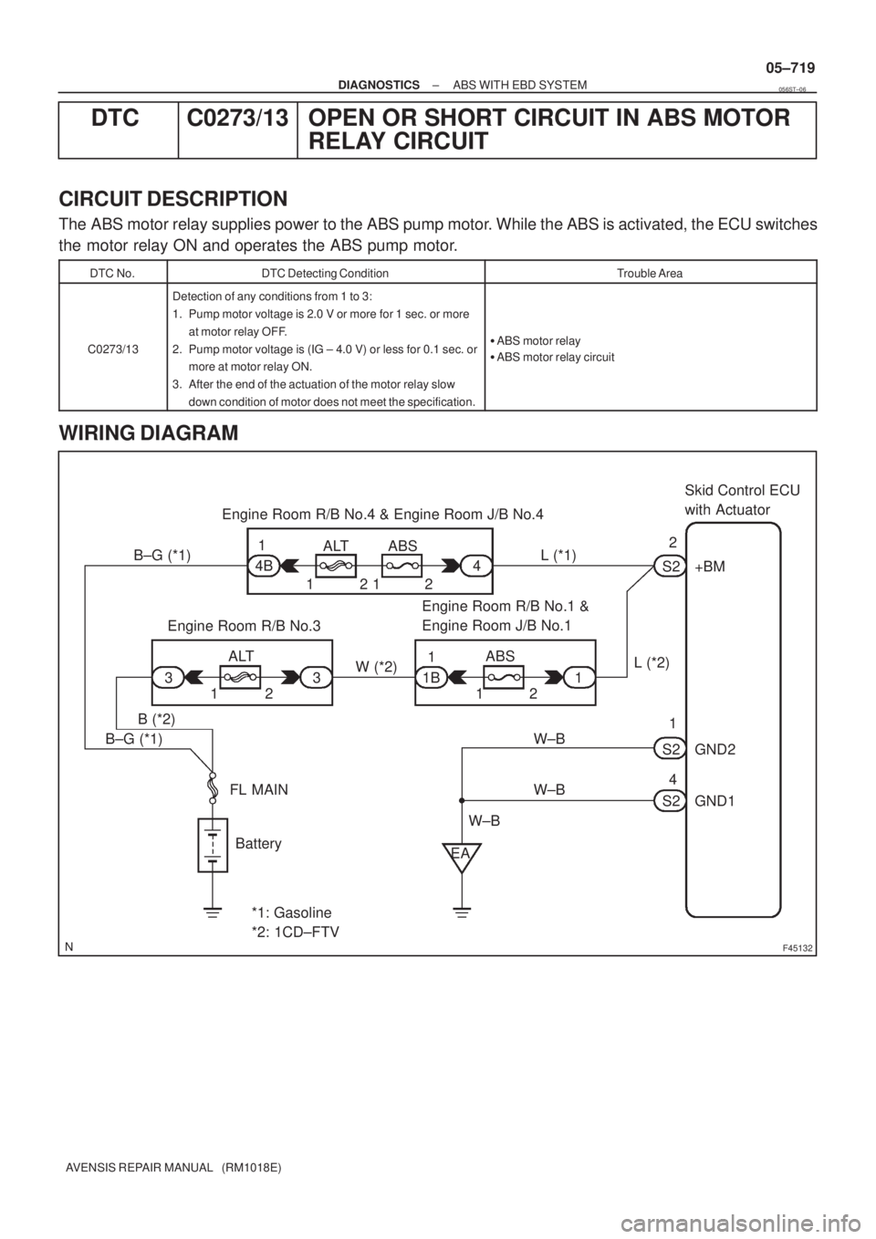
DTC C0273/13 OPEN OR SHORT CIRCUIT IN ABS MOTOR
RELAY CIRCUIT
CIRCUIT DESCRIPTION
The ABS motor relay supplies power to the ABS pump motor. While the ABS is activated, the ECU switches
the motor relay ON and operates the ABS pump motor.
DTC No.DTC Detecting ConditionTrouble Area
C0273/13
Detection of any conditions from 1 to 3:
1. Pump motor voltage is 2.0 V or more for 1 sec. or more
at motor relay OFF.
2. Pump motor voltage is (IG ± 4.0 V) or less for 0.1 sec. or
more at motor relay ON.
3. After the end of the actuation of the motor relay slow
down condition of motor does not meet the specification.
�ABS motor relay
�ABS motor relay circuit
WIRING DIAGRAM
056ST±06
Page 789 of 5135
F45132
Battery FL MAINSkid Control ECU
with Actuator
B±G (*1) R (*1)
1 ALT ABS Engine Room R/B No.4 & Engine Room J/B No.4
1
4B
W±BS2
S21 3
+BS
12
1 2
GND1 GND2
S24
W±BW±B
*1: Gasoline
*2: 1CD±FTVEA4
R (*2)
W (*2)
2 12 33 11B1ABS ALT Engine Room R/B No.3Engine Room R/B No.1 &
Engine Room J/B No.1
B (*2)
B±G (*1)
± DIAGNOSTICSABS WITH EBD SYSTEM
05±717
AVENSIS REPAIR MANUAL (RM1018E)
DTC C0226/21 SFR SOLENOID CIRCUIT
DTC C0236/22 SFL SOLENOID CIRCUIT
DTC C0246/23 SRR SOLENOID CIRCUIT
DTC C0256/24 SRL SOLENOID CIRCUIT
CIRCUIT DESCRIPTION
This solenoid goes on when receiving signals from the ECU and controls the pressure acting on the wheel
cylinders to control the braking force.
DTC No.DTC Detecting ConditionTrouble Area
C0226/21
C0236/22
C0246/23
C0256/24
Solenoid valve signal does not match to the check result.�Each solenoid circuit
WIRING DIAGRAM
050XQ±12
Page 791 of 5135

F45131
Skid Control ECU
with Actuator
2 1 G R
177
RL+
RL±
S2 S2
A32
ABS Speed Sensor
Rear LH
8
19
S2 S2RR+ RR±
R
A33
ABS Speed Sensor
Rear RH 2 1
V G
P 2
1
110 IB1
IB1
IM1IE2 V P
V
P
IM1IE2 1011
±
DIAGNOSTICS ABS WITH EBD SYSTEM
05±713
AVENSIS REPAIR MANUAL (RM1018E)
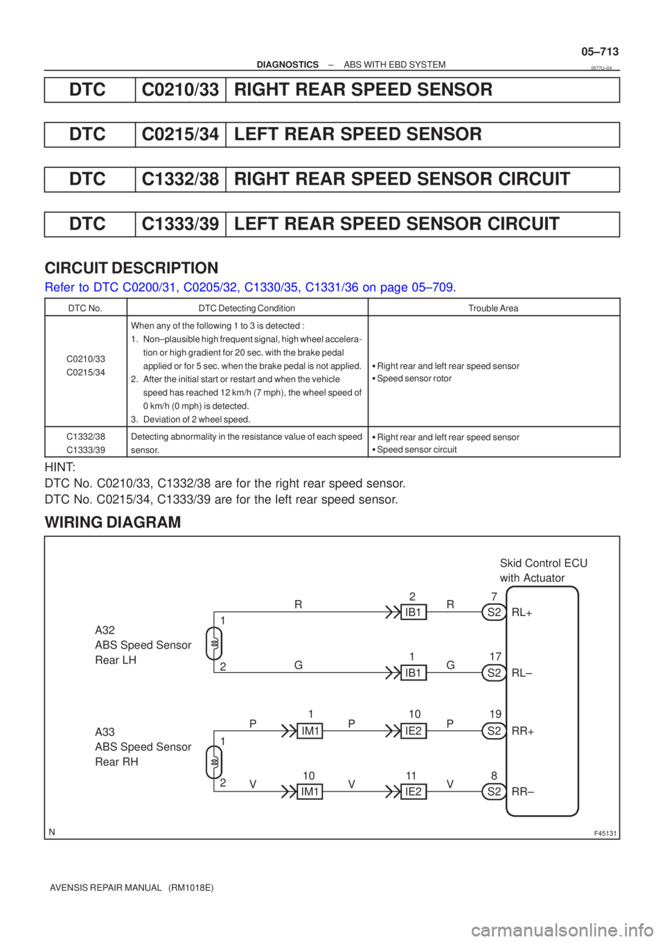
DTCC0210/33RIGHT REAR SPEED SENSOR
DTCC0215/34LEFT REAR SPEED SENSOR
DTCC1332/38RIGHT REAR SPEED SENSOR CIRCUIT
DTCC1333/39LEFT REAR SPEED SENSOR CIRCUIT
CIRCUIT DESCRIPTION
Refer to DTC C0200/31, C0205/32, C1330/35, C1331/36 on page 05±709.
DTC No.DTC Detecting ConditionTrouble Area
C0210/33
C0215/34
When any of the following 1 to 3 is detected :
1. Non±plausible high frequent signal, high wheel accelera-
tion or high gradient for 20 sec. with the brake pedal
applied or for 5 sec. when the brake pedal is not applied.
2. After the initial start or restart and when the vehicle
speed has reached 12 km/h (7 mph), the wheel speed of
0 km/h (0 mph) is detected.
3. Deviation of 2 wheel speed.
� Right rear and left rear speed sensor
� Speed sensor rotor
C1332/38
C1333/39Detecting abnormality in the resistance value of each speed
sensor.�Right rear and left rear speed sensor
� Speed sensor circuit
HINT:
DTC No. C0210/33, C1332/38 are for the right rear speed sensor.
DTC No. C0215/34, C1333/39 are for the left rear speed sensor.
WIRING DIAGRAM
0577U±04
Page 796 of 5135
F40884
2
1
W
B10
9FR+
FR± S2 A4
ABS Speed Sensor
Front LH
A5
ABS Speed Sensor
Front RH2
16
S25
S2
S2FL+
FL± L±Y
R±LSkid Control ECU
with Actuator
05±710
± DIAGNOSTICSABS WITH EBD SYSTEM
AVENSIS REPAIR MANUAL (RM1018E)
WIRING DIAGRAM
INSPECTION PROCEDURE
HINT:
Start the inspection from step 1 if you are using the hand±held tester and start from step 2 if you are not using
the hand±held tester.
1 READ VALUE OF HAND±HELD TESTER(FRONT SPEED SENSOR)
(a) Select the item ºWHEEL SPEED FL (FR)º in the DATA LIST and read the value displayed on the hand±
held tester.
(b) Check that there is no difference between the speed value output from the speed sensor displayed
on the hand±held tester and the speed value displayed on the speedometer when driving the vehicle.
OK:
There is almost no difference in the displayed speed value.
HINT:
There is tolerance of �10 % in the speedometer indication.
OK Go to step 5
NG
Page 830 of 5135
F45137
Skid Control ECU
with Actuator
W±B (*1) W±B (*1)W±B (*2)W (*2) W (*1) W (*1) W
S2 TS13
W±B (*2)
CB CA6 3IE2 12 J8
J/C
D
A
IO IP CG TS D5
DLC3 1AZ±FE:
4 12
D
ACenter J/B
J16
J/C
*1: LHD
*2: RHD
C87489
Skid Control ECU
with Actuator
W±B (*1) W±B (*1)W±B (*2) W (*2)W (*1) W (*1) W
S2 TS13
W±B (*2)
CB CA6 3IE2 12 J8
J/C
D
A
IP CG TS D5
DLC3 Except 1AZ±FE:
4 12 D
ACenter J/B
J16
J/C
*1: LHD
*2: RHDIO: Gasoline
IL: 1CD±FTV D
B
J20 J21W (*2) J/C
05±750
± DIAGNOSTICSABS WITH EBD SYSTEM
AVENSIS REPAIR MANUAL (RM1018E)
TS TERMINAL CIRCUIT
CIRCUIT DESCRIPTION
The sensor check circuit detects troubles in the sensor signal which cannot be detected by the DTC check.
Connecting terminals Ts and CG of the DLC3 starts the check.
WIRING DIAGRAM
05C5D±01