Page 719 of 5135

A81512
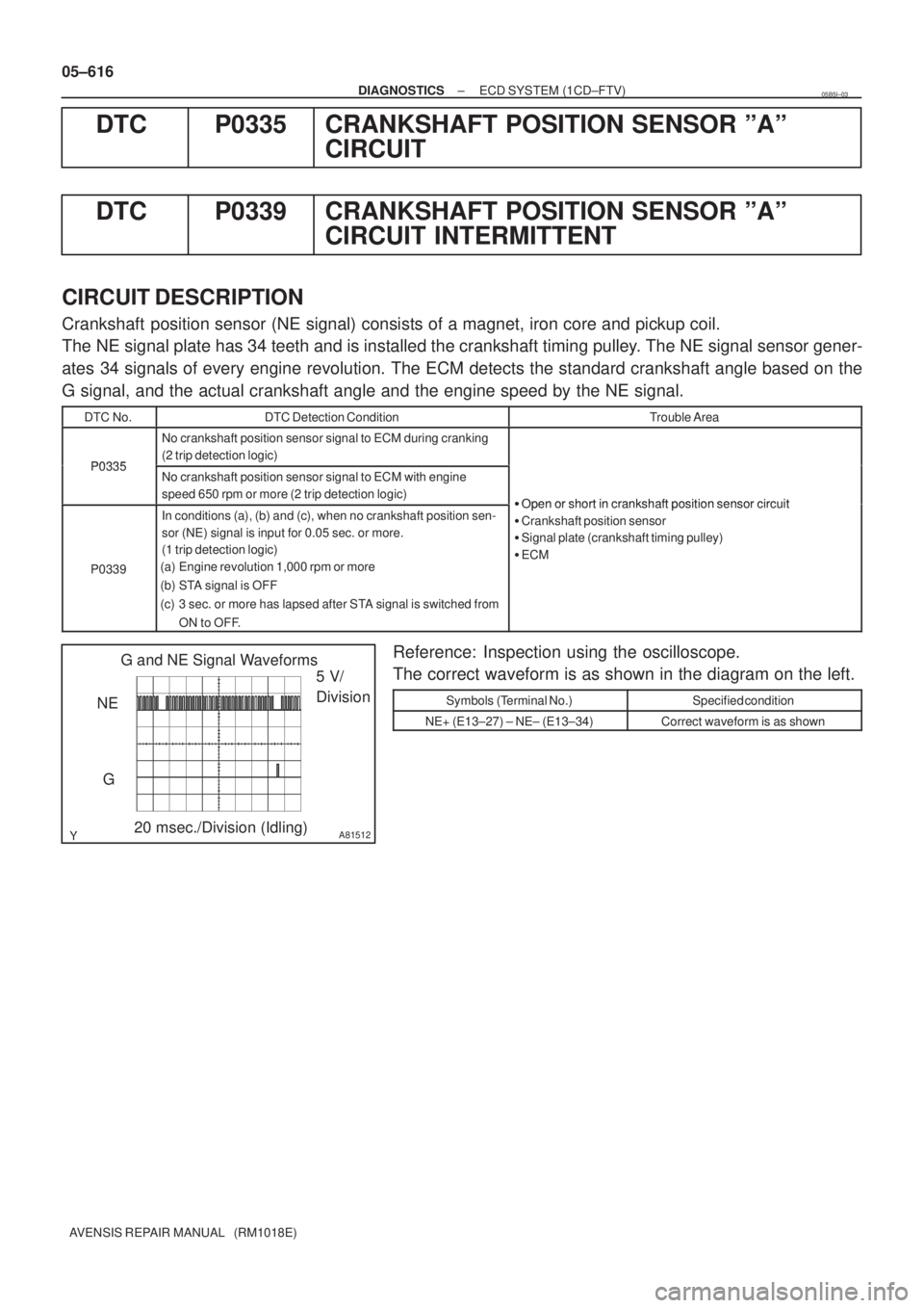
G and NE Signal Waveforms
5 V/
Division
G
20 msec./Division (Idling) NE 05±616
± DIAGNOSTICSECD SYSTEM (1CD±FTV)
AVENSIS REPAIR MANUAL (RM1018E)
DTC P0335 CRANKSHAFT POSITION SENSOR ºAº
CIRCUIT
DTC P0339 CRANKSHAFT POSITION SENSOR ºAº
CIRCUIT INTERMITTENT
CIRCUIT DESCRIPTION
Crankshaft position sensor (NE signal) consists of a magnet, iron core and pickup coil.
The NE signal plate has 34 teeth and is installed the crankshaft timing pulley. The NE signal sensor gener-
ates 34 signals of every engine revolution. The ECM detects the standard crankshaft angle based on the
G signal, and the actual crankshaft angle and the engine speed by the NE signal.
DTC No.DTC Detection ConditionTrouble Area
P0335
No crankshaft position sensor signal to ECM during cranking
(2 trip detection logic)
P0335No crankshaft position sensor signal to ECM with engine
speed 650 rpm or more (2 trip detection logic)
�Open or short in crankshaftposition sensor circuit
P0339
In conditions (a), (b) and (c), when no crankshaft position sen-
sor (NE) signal is input for 0.05 sec. or more.
(1 trip detection logic)
(a) Engine revolution 1,000 rpm or more
(b) STA signal is OFF
(c) 3 sec. or more has lapsed after STA signal is switched from
ON to OFF.�Open or short in crankshaft position sensor circuit
�Crankshaft position sensor
�Signal plate (crankshaft timing pulley)
�ECM
Reference: Inspection using the oscilloscope.
The correct waveform is as shown in the diagram on the left.
Symbols (Terminal No.)Specified condition
NE+ (E13±27) ± NE± (E13±34)Correct waveform is as shown
05B5I±03
Page 720 of 5135
A81004
ECM
C1
Camshaft Position Sensor
NE± NE+ G1
2723
E12
L P
E13
R
BR
EI C6
Crankshaft Position Sensor1
2
1
234
E1331
E12G±
G (Shielded)(Shielded)
EE
E
J12
J/CE1
± DIAGNOSTICSECD SYSTEM (1CD±FTV)
05±617
AVENSIS REPAIR MANUAL (RM1018E)
WIRING DIAGRAM
INSPECTION PROCEDURE
HINT:
�Perform troubleshooting of DTC P0335 first. If no trouble is found, troubleshoot the engine mechanical
systems.
�Read freeze frame data using ��� ��������� ��
�� . Freeze frame data records the engine conditions
when a malfunction is detected. When troubleshooting, it is useful for determining whether the vehicle
was running or stopped, the engine was warmed up or not, etc. at the time of the malfunction.
Page 723 of 5135
A81003
MREL B±W
GR8
3 EFI MAIN Relay
W±BE9 E13
2 IE1
EE1
EFIB±Y 1
B5
Battery FL MAINV4
VRV
VN 10
1
1
1
1A1
1
12 12 W
B±W 10GR
Engine Room R/B No. 1ECM
2
1
Engine Room
R/B No. 3 3
3 B
EC 05±612
± DIAGNOSTICSECD SYSTEM (1CD±FTV)
AVENSIS REPAIR MANUAL (RM1018E)
DTC P0234 TURBO/SUPER CHARGER OVERBOOST
CONDITION
DTC P0299 TURBO/SUPER CHARGER UNDERBOOST
DTC P1251 TURBO/SUPER CHARGER OVERBOOST
CONDITION (TOO HIGH)
CIRCUIT DESCRIPTION
DTC No.DTC Detection ConditionTrouble Area
P0234
When the condition that the turbocharger pressure exceeds the
standard value for 0.5 sec. or more. (1 trip detection logic)�VRV
�Open or short in VRV circuit
�TurbochargerP0234
P0299
P1251Actual turbocharger pressure is deviated 20 kPa (0.2 kgf/cm2,
2.9 psi) or more from the simulated target pressure based on
the engine speed and fue injection volume for 60 seconds.�Turbocharger
�Vacuum hose
�EGR valve
�ECM
WIRING DIAGRAM
05CPS±01
Page 727 of 5135

A81481
EDU Wiring DiagramCOM3
COM1 COM2
Pressure
Discharge
Valve
Injector
INJ#1
INJ#4INJ#2INJ#3
PRV
GND
EDU Connector
Control
Circuit
DC/DC
Converter
BATTERY
IJT#1
IJT#4
IJT#2
IJT#3PRDIJF
ECM
Maximum 150 V
Confirmation
Pulse Command
Pulse
Warning:
Terminal J, I, H, K, L, M, N and S are high voltage
E5
E4
Maximum 150 V
05±604
±
DIAGNOSTICS ECD SYSTEM(1CD±FTV)
AVENSIS REPAIR MANUAL (RM1018E)
DTCP0200INJECTOR CIRCUIT / OPEN
HINT:
�For more information on the EDU, see page 05±517.
�If P0200 are present, Use the diagnostic trouble code matrix for fuel sy\
stem, see page 05±517.
CIRCUIT DESCRIPTION
The EDU has been adopted to drive the injector at high speeds. The EDU has \
realized high±speed driving
under high fuel pressure conditions using the DC/DC converter that provides a\
high±voltage, quick±charging
system.
Soon after the EDU receives an injection command signal (IJT) from the\
ECM, the EDU responds to the com-
mand with injector injection confirmation signal (IJF) when the current is\
applied to the injector.
05CPR±01
Page 729 of 5135

A81001
B±Y
BATTECM
E102 7
IE3B±Y
10
EE17
IO1
INJF E1325
R±B
E57
IJF B±W
+B
E91
B±W 8
IK1 B±W
GR
MREL 8
GR 2
IE1 E9
Y
IREL 10 4
IE2 E9Y GR
B±W B±W
B±Y111
1 1 1 11
1 3
2 5EFI
MAIN
Relay1 3
2 5EDU
Relay
R±B
B±Y
B7
EE1(LHD) (RHD)
EDU
#1 E1324
G±W
IJT#1
#2 E1323
W±R
IJT#2
#3 E1322
R±W
IJT#3
#4 E1321
W±L
IJT#4E56
E53
E52
E55
1
11 2
EFI
1A
3
3
B
FL MAIN
BatteryEngine
Room
R/B No. 1
Engine Room
R/B No. 3W±B
W±B
EC(Shielded)
D J12 E J12
E J13 D J13
BR J/CBR
W±B G
EIE48
BATTERY
E5 GND1W INJ#1
E44
12B±R I5 Injector No. 1
B
INJ#4
E43
12B±R I8 Injector No. 4
Y
INJ#2
E42
12L I6 Injector No. 2
V
INJ#3
E41
12L I7 Injector No. 3 B±R
COM1E45
L
COM2 E46 BRE58
E47
COM3 BPRD E1332
R±L
E54
PRD Engine
Room
R/B No. 1
(Shielded)
D J12BRPRV 1
EA1
2
EA1 1
2W
W
B
P3
Pressure
Discharge
Valve
05±606
± DIAGNOSTICSECD SYSTEM (1CD±FTV)
AVENSIS REPAIR MANUAL (RM1018E)
TYPICAL MALFUNCTION THRESHOLDS
Threshold
If injection missing counter* is accumulated a specified number of times successively, or if injection missing counter for either one of the
cylinders is accumulated a specified number of times successively (Approximately 1 second or more).
*: Injection missing counter increments when no IJF signal from the EDU despite the ECM sending the IJT signal.
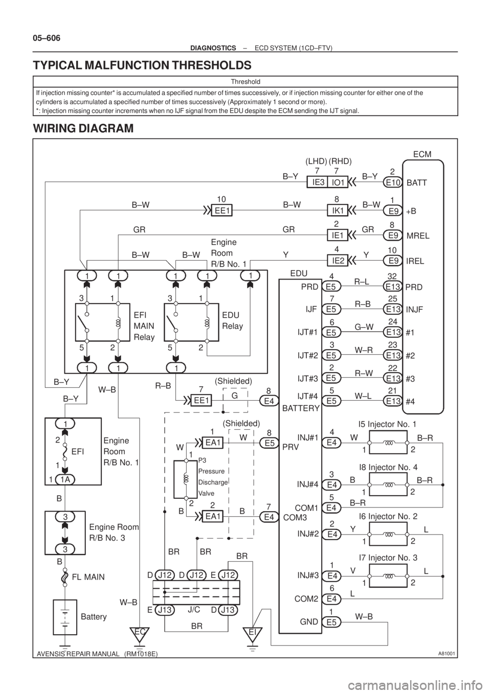
WIRING DIAGRAM
Page 730 of 5135

A81508
ECM EDU
IJT#1 INJF
COM1 IJF
IJT#4
IJT#2
IJT#3 #1
#4
#2
#3INJ#1
INJ#4
INJ#2
INJ#3 COM2
Injector
AB
Warning: Terminal COM1, COM2, and INJ#1 to 4 are high±voltage
C DHigh±voltage Area
A09438
#1
#2#3
#45 V/
Division
20 msec./Division Signal Waveform
± DIAGNOSTICSECD SYSTEM (1CD±FTV)
05±607
AVENSIS REPAIR MANUAL (RM1018E)
PULSE GENERATION INSPECTION
HINT:
Problem area can be identified by inspecting waveform at the following inspection points.
HINT:
Inspect the following inspection points ºA and Dº or º B and Cº at the same time.
Malfunction pointTrouble area
A�ECM
B (if A is normal)�Open or short in º#1 to #4 (ECM)º ± ºIJT#1 to #4 (EDU)º harness or connector.
C (if A and B are normal)
�Open or short in ºINJ#1 to #4 (EDU)º ± ºCOM1 and/or COM2º (EDU) circuit.
�Injector
�EDU
D (if A, B and C are normal)�Open or short in ºIJF (EDU)º ± ºINJF (ECM)º circuit. (P1271 is set simultaneously)
(a) Reference: Inspect using the oscilloscope.
The correct waveform is as shown in the diagram on the
left.
Inspection PointsSpecified Condition
A and BCorrect waveform is as shown
Page 731 of 5135

A81511
5 V/
Division
20 msec./Division INJFSignal Waveform
05±608
± DIAGNOSTICSECD SYSTEM (1CD±FTV)
AVENSIS REPAIR MANUAL (RM1018E)
(b) Reference: Inspect using the oscilloscope.
The correct waveform is as shown in the diagram on the
left.
Inspection PointsSpecified Condition
C and DCorrect waveform is as shown
INSPECTION PROCEDURE
HINT:
�If P0200 and P1271 are present simultaneously, there is open in the INJF wire harness between the
EDU and ECM, or there is open in the wire harness for both of the injector the pressure discharge valve.
�Read freeze frame data using ��� ��������� ��
�� . Freeze frame data records the engine conditions
when a malfunction is detected. When troubleshooting, it is useful for determining whether the vehicle
was running or stopped, the engine was warmed up or not, etc. at the time of the malfunction.
1 CHECK OTHER DTC OUTPUT(BESIDES DTC P0200)
(a) Connect the hand±held tester to the DLC3.
(b) Turn the ignition switch ON and push the hand±held tester main switch ON.
(c) Select the item ºDIAGNOSIS / OBD/MOBD / DTC INFO / CURRENT CODESº.
(d) Read the DTCs.
Result:
Display (DTC output)Proceed to
DTC P0200 and P1238 are outputA
Only DTC P0200 is outputB
B Go to step 3
A
2 READ VALUE OF HAND±HELD TESTER(COMPENSATION OF INJECTION
QUANTIFY BETWEEN CYLINDERS)
(a) Connect the hand±held tester to the DLC3.
(b) Turn the ignition switch ON and push the hand±held tester main switch ON.
(c) Start the engine.
(d) Select the item ºDIAGNOSIS / OBD/MOBD / DATA LIST / ALL / INJ VOLUME FBº and read its value
displayed on the hand±held tester.
Result:
STD ± 3 to 3 mm
3/st
Maximum ± 4.9 to 4.9 mm
3/st
(e) The cylinder that has a misspecification compensation value is a faulty cylinder, use the following flow-
chart to inspect and repair the cylinder.
GO
Page 737 of 5135

A10940
ECM
THF E2
F18
Fuel Temp. Sensor
1
2
5V
R
E1
E13
E13 28 29
L
BR
05±600
±
DIAGNOSTICS ECD SYSTEM(1CD±FTV)
AVENSIS REPAIR MANUAL (RM1018E)
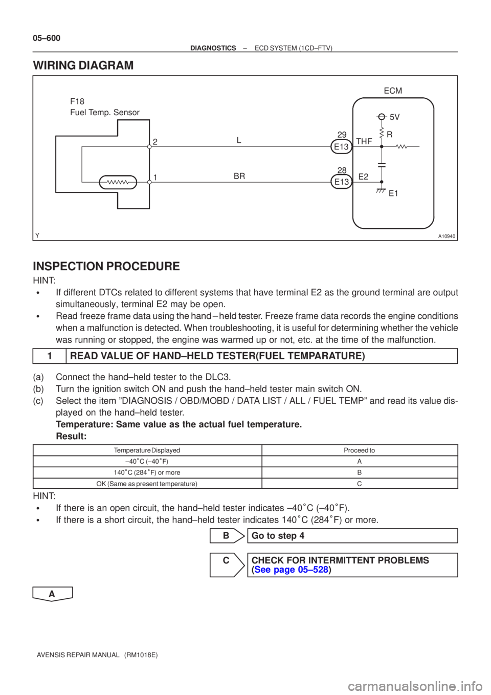
WIRING DIAGRAM
INSPECTION PROCEDURE
HINT:
�If different DTCs related to different systems that have terminal E2 as the ground terminal are output
simultaneously, terminal E2 may be open.
�Read freeze frame data using
\b�\b�
��\b� �
�\f
��� Freeze frame data records the engine conditions
when a malfunction is detected. When troubleshooting, it is useful for d\
etermining whether the vehicle
was running or stopped, the engine was warmed up or not, etc. at the time o\
f the malfunction.
1READ VALUE OF HAND±HELD TESTER(FUEL TEMPARATURE)
(a)Connect the hand±held tester to the DLC3.
(b)Turn the ignition switch ON and push the hand±held tester main switch \
ON.
(c)Select the item ºDIAGNOSIS / OBD/MOBD / DATA LIST / ALL / FUEL TEMPº and read its value dis- played on the hand±held tester.
Temperature: Same value as the actual fuel temperature.
Result:
Temperature DisplayedProceed to
±40�C (±40 ��)A
140 �C (284 ��) or moreB
OK (Same as present temperature)C
HINT:
�If there is an open circuit, the hand±held tester indicates ±40 �C (±40 �F).
�If there is a short circuit, the hand±held tester indicates 140 �C (284 �F) or more.
BGo to step 4
CCHECK FOR INTERMITTENT PROBLEMS (See page 05±528)
A