Page 608 of 5135
A76877
ECM
+BM
FL MAINTHROTTLE Engine Room J/B No. 1 and
Engine Room R/B No. 1
E10
IE2 1A 4B15
2 Engine Room J/B No. 4
6
B±G
Battery4A1
B±G
1 1
1G±R G±Y
± DIAGNOSTICSSFI SYSTEM (1AZ±FSE)
05±487
AVENSIS REPAIR MANUAL (RM1018E)
DTC P2118 THROTTLE ACTUATOR CONTROL MOTOR
CURRENT RANGE/PERFORMANCE
CIRCUIT DESCRIPTION
If this DTC is detected, the ECM shuts down the power for the throttle motor, and the throttle valve is closed
by the return spring. And the throttle valve is locked at a certain opening angle. Also, the whole electronically
controlled throttle operation is cancelled until the system returns to normal and the ignition switch is turned
OFF.
HINT:
This electrical throttle control system (ETCS) does not use the throttle cable.
DTC No.DTC Detection ConditionTrouble Area
P2118Open in ETCS power source circuit�Open in ETCS power source circuit
�ECM
WIRING DIAGRAM
05CKR±01
Page 611 of 5135

A54292
T1
Throttle Control Motor
(Built in Throttle Body)
2
1B
WECM
3
2
17M+
M±
E11
(Shielded)
E11
E11
GE01
± DIAGNOSTICSSFI SYSTEM (1AZ±FSE)
05±483
AVENSIS REPAIR MANUAL (RM1018E)
DTC P2102 THROTTLE ACTUATOR CONTROL MOTOR
CIRCUIT LOW
DTC P2103 THROTTLE ACTUATOR CONTROL MOTOR
CIRCUIT HIGH
CIRCUIT DESCRIPTION
The throttle motor is operated by the ECM and it opens and closes the throttle valve.
The opening angle of the throttle valve is detected by the throttle position sensor which is mounted on the
throttle body. It provides feedback to the ECM to control the throttle motor in order to regulate the throttle
valve opening angle properly in response to the driving condition.
If this malfunction is detected, the ECM shuts down the power for the throttle motor, and the throttle valve
is closed by the return spring. And the throttle valve is locked at a certain opening angle. Also, the whole
electronically controlled throttle operation is cancelled until the system returns to normal and the ignition
switch is turned OFF.
HINT:
This electrical throttle system does not use the throttle cable.
DTC No.DTC Detection ConditionTrouble Area
P2102
Conditions (a) and (b) continue for 2.0 seconds:
(a) Throttle control motor output duty greater than 80 %
(b) Throttle control motor current less than 0.5 A�Open in throttle control motor circuit
�Throttle control motor
�ECM
Throttle control motor current greater than 10 A�Short in throttle control motor circuit
P2103Condition (a) continues for 0.6 seconds:
(a) Throttle control motor current greater than 7 A
Short in throttle control motor circuit
�Throttle control motor
�ECM
WIRING DIAGRAM
05CKP±01
Page 613 of 5135
A76875
ECM
SCV 5
E13 EFI Relay
1 1 23
Engine Room
J/B No. 4B±W
1MREL 8
E9
Battery FL MAIN B±G2 5
GR
V6
VSV (Intake Air Control Valve)
2
L±B EFI No. 2 1
B±G
W±B
ECW±B
4A
14B11AEFI
1B±Y
1
2 4
4
44
4
4
B±W Engine Room
R/B No. 1
and
Engine Room
J/B No. 1Engine Room R/B No. 4
GR
B±W
EA113IE1 2 05±480
± DIAGNOSTICSSFI SYSTEM (1AZ±FSE)
AVENSIS REPAIR MANUAL (RM1018E)
DTC P2008 INTAKE MANIFOLD RUNNER CONTROL
CIRCUIT / OPEN (BANK 1)
CIRCUIT DESCRIPTION
The Intake Air Control valve (IACV) is opened and shut by the actuator with intake manifold vacuum.
It stabilizes the engine combustion. The IACV operation generates swirl air flow in the cylinder.
DTC No.DTC Detection ConditionTrouble Area
P2008Open or short in VSV for IACV circuit 0.5 sec. or more
(2 trip detection logic)�Open of short in VSV for IACV circuit
�VSV for IACV
�ECM
WIRING DIAGRAM
05CK5±01
Page 616 of 5135

A76876
ECM
J13G
FP+ 6
R
E12
D(Shielded)
J13 E
J12 E J12D
BRBR
EEJ/C21 S3
Fuel Pump
(High Pressure)
(Spill Valve)
G
FP± 3
E12
(Shielded) BR
± DIAGNOSTICSSFI SYSTEM (1AZ±FSE)
05±477
AVENSIS REPAIR MANUAL (RM1018E)
DTC P1235 HIGH PRESSURE FUEL PUMP CIRCUIT
CIRCUIT DESCRIPTION
The fuel pump (high pressure) is an electronically controlled plunger type fuel pump (high pressure) which
is driven by the cam provided on the intake cam shaft rear end on the cylinder head.
The fuel pump (high pressure) increases the pressure of the fuel fed from the fuel pump (low pressure) in
the fuel tank at 8 to 13 MPa (81.6 to 132.6 kgf/cm
2, 1,160 to 1,885 psi) according to the operating condition,
and it feeds the fuel to the fuel delivery pipe.
DTC No.DTC Detection conditionTrouble Area
O h ti f l (hi h ) i itf 1�Open or short in fuel pump (high pressure)
P1235Open or short in fuel pump (high pressure) circuit for 1sec. or
more
�Oen or short in fuel um (high ressure)
�Fuel pump (high pressure)P1235moreFuel um (high ressure)
�ECM
WIRING DIAGRAM
INSPECTION PROCEDURE
HINT:
Read freeze frame data using hand±held tester. Freeze frame data records the engine conditions when the
malfunction is detected. When troubleshooting, it is useful for determining whether the vehicle was running
or stopped, the engine was warmed up or not, the air±fuel ratio was lean or rich, etc. at the time of the mal-
function.
05CK4±01
Page 650 of 5135

05CP9±01
A81021
Common Rail System Diagram (1CD±FTV Fuel System)
Sensors
ECM
EDU
Common Rail
Fuel Pressure SensorPressure Discharge
Valve
Supply Pump Assy
Suction Control ValveFuel TankInjector
Fuel Filter
: High±pressure Area
± DIAGNOSTICSECD SYSTEM (1CD±FTV)
05±517
AVENSIS REPAIR MANUAL (RM1018E)
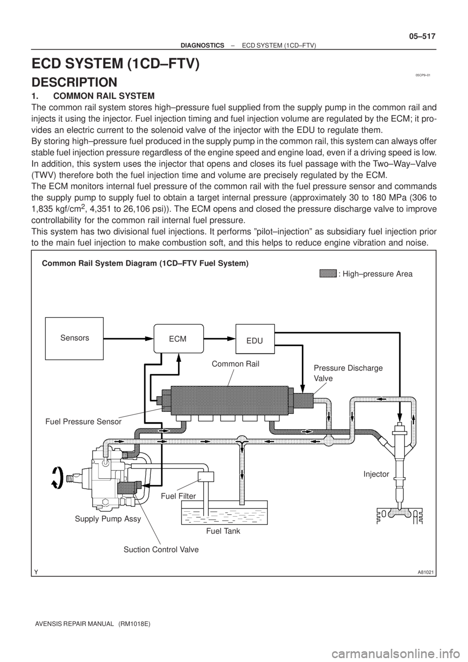
ECD SYSTEM (1CD±FTV)
DESCRIPTION
1. COMMON RAIL SYSTEM
The common rail system stores high±pressure fuel supplied from the supply pump in the common rail and
injects it using the injector. Fuel injection timing and fuel injection volume are regulated by the ECM; it pro-
vides an electric current to the solenoid valve of the injector with the EDU to regulate them.
By storing high±pressure fuel produced in the supply pump in the common rail, this system can always offer
stable fuel injection pressure regardless of the engine speed and engine load, even if a driving speed is low.
In addition, this system uses the injector that opens and closes its fuel passage with the Two±Way±Valve
(TWV) therefore both the fuel injection time and volume are precisely regulated by the ECM.
The ECM monitors internal fuel pressure of the common rail with the fuel pressure sensor and commands
the supply pump to supply fuel to obtain a target internal pressure (approximately 30 to 180 MPa (306 to
1,835 kgf/cm
2, 4,351 to 26,106 psi)). The ECM opens and closed the pressure discharge valve to improve
controllability for the common rail internal fuel pressure.
This system has two divisional fuel injections. It performs ºpilot±injectionº as subsidiary fuel injection prior
to the main fuel injection to make combustion soft, and this helps to reduce engine vibration and noise.
Page 651 of 5135

A81477
Engine Control System Diagram
Accelerator Pedal
Position Sensor
Ignition
Switch Signal
Starter Signal
Vehicle Speed Signal
DLC3
Battery Voltage
Other Signal
Fuel Tank
Suction Control Valve
Supply Pump
Generator
ECMPressure Discharge Valve
Fuel Pressure Sensor
EDU Relay
EDU
Mass Air Flow Meter
Atmospheric
Temp. SensorEGR Cooler
Turbo ChargerInter Cooler
Intake Shatter
Intake Air Temp.
SensorEGR Valve
Injector
Manifold
Absolute
Sensor
Glow
Plug
Glow
Relay Crankshaft Position Sensor VRV for
Turbo
ChargerEngine Coolant
Temp. SensorCamshaft
Position
SensorCommon Rail
Vacuum Pump
(INJT PRD)(INJF)
05±518
± DIAGNOSTICSECD SYSTEM (1CD±FTV)
AVENSIS REPAIR MANUAL (RM1018E)
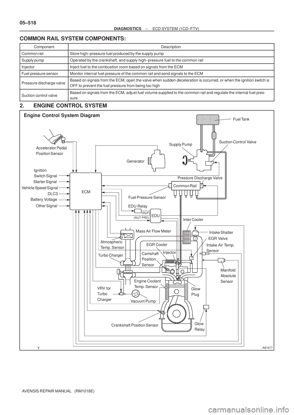
COMMON RAIL SYSTEM COMPONENTS:
ComponentDescription
Common railStore high±pressure fuel produced by the supply pump
Supply pumpOperated by the crankshaft, and supply high±pressure fuel to the common rail
InjectorInject fuel to the combustion room based on signals from the ECM
Fuel pressure sensorMonitor internal fuel pressure of the common rail and send signals to the ECM
Pressure discharge valveBased on signals from the ECM, open the valve when sudden deceleration is occurred, or when the ignition switch is
OFF to prevent the fuel pressure from being too high
Suction control valveBased on signals from the ECM, adjust fuel volume supplied to the common rail and regulate the internal fuel pres-
sure
2. ENGINE CONTROL SYSTEM
Page 652 of 5135
A81479
Injection Control Diagram
Accelerator Pedal
Position Sensor
Camshaft Position Sensor
Crankshaft Position Sensor
(NE Signal)
Other Sensor
Fuel TankFeed
Pump
Eccentric
CamPlungerCheck Valve Fuel Pressure SensorCommon Rail EDU
TWV
Orifice
Orifice
Nozzle
NeedleControl
Chamber
Piston
Injector ECM
Suction
Control
Valve
± DIAGNOSTICSECD SYSTEM (1CD±FTV)
05±519
AVENSIS REPAIR MANUAL (RM1018E)
3. INJECTION CONTROL SYSTEM
The ECM controls the fuel injection system using the injector and the supply pump. The ECM determines
the fuel injection volume and injection timing by controlling duration and timing of the energizing to the sole-
noid valve of the injector, and determines injection pressure by controlling the Suction Control Valve located
on the supply pump.
The feed pump is used to pump fuel from the fuel tank into the supply pump.
Page 653 of 5135
A81480
Plunger A: Pumping End
Plunger B: Suction EndPlunger A: Suction Start
Plunger B: Pumping Start Check Valve
Eccentric Cam
Ring Cam
Plunger B
Plunger A
Plunger A: Pumping Start
Plunger B: Suction StartPlunger A: Suction End
Plunger B: Pumping End Supply Pump Operation Diagram
From
Feed Pump
To Common Rail Suction
Control
Valve
05±520
± DIAGNOSTICSECD SYSTEM (1CD±FTV)
AVENSIS REPAIR MANUAL (RM1018E)
4. SUPPLY PUMP OPERATION SYSTEM
The rotation of the eccentric cam causes the ring cam pushes plunger A upward as illustrated below. The
spring force pulls plunger B (which is located on opposite of plunger A) upward. As a result, plunger B draws
fuel in, and plunger A pumps fuel at the same time.