Page 5110 of 5135
A95728
A95729
Connecting Bearing Cap: Connecting Bearing:
TAIHO Mark Lot. Number Mark
TAIHO Made
FEDERAL MOGUL
/GLYCO Made
MarkMark
14–54
– ENGINE MECHANICALCYLINDER BLOCK ASSY (1ZZ–FE/3ZZ–FE)
1ZZ–FE,3ZZ–FE ENGINE REPAIR MANUAL
(RM1099E)
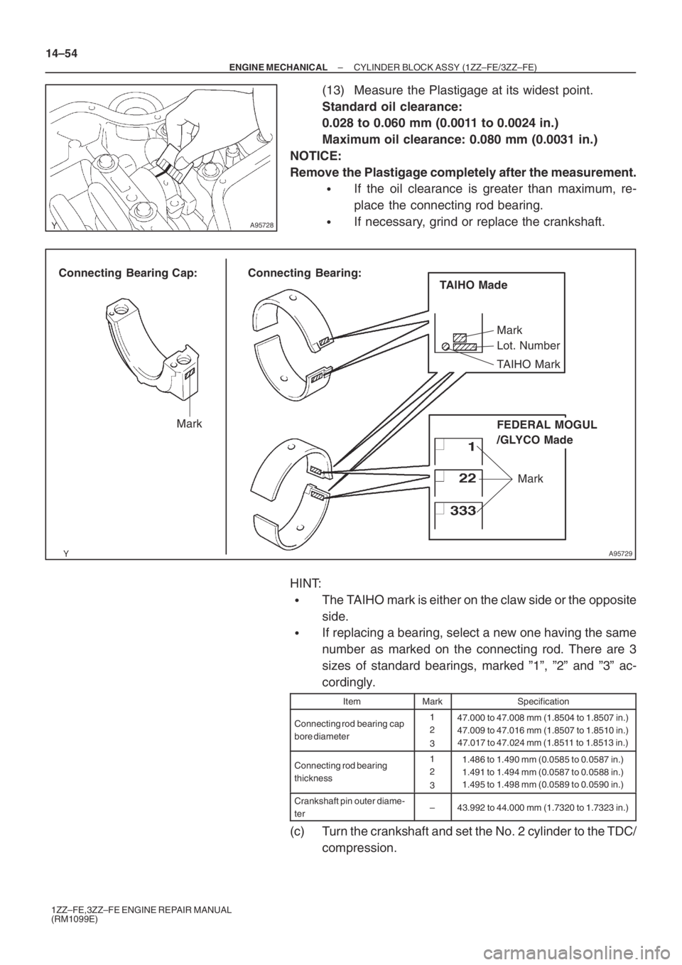
(13) Measure the Plastigage at its widest point.
Standard oil clearance:
0.028 to 0.060 mm (0.0011 to 0.0024 in.)
Maximum oil clearance: 0.080 mm (0.0031 in.)
NOTICE:
Remove the Plastigage completely after the measurement.
�If the oil clearance is greater than maximum, re-
place the connecting rod bearing.
�If necessary, grind or replace the crankshaft.
HINT:
�The TAIHO mark is either on the claw side or the opposite
side.
�If replacing a bearing, select a new one having the same
number as marked on the connecting rod. There are 3
sizes of standard bearings, marked ”1”, ”2” and ”3” ac-
cordingly.
ItemMarkSpecification
Connecting rod bearing cap
bore diameter1
2
347.000 to 47.008 mm (1.8504 to 1.8507 in.)
47.009 to 47.016 mm (1.8507 to 1.8510 in.)
47.017 to 47.024 mm (1.8511 to 1.8513 in.)
Connecting rod bearing
thickness1
2
31.486 to 1.490 mm (0.0585 to 0.0587 in.)
1.491 to 1.494 mm (0.0587 to 0.0588 in.)
1.495 to 1.498 mm (0.0589 to 0.0590 in.)
Crankshaft pin outer diame-
ter–43.992 to 44.000 mm (1.7320 to 1.7323 in.)
(c) Turn the crankshaft and set the No. 2 cylinder to the TDC/
compression.
Page 5111 of 5135
A95721
Matchmark
A95723
SST
A01159
Plastigage
A95727
Front Mark
– ENGINE MECHANICALCYLINDER BLOCK ASSY (1ZZ–FE/3ZZ–FE)
14–55
1ZZ–FE,3ZZ–FE ENGINE REPAIR MANUAL
(RM1099E)
(d) Measure the oil clearance of the No. 1 and No. 4 cylin-
ders.
NOTICE:
Do not turn the crankshaft during the measurement.
(1) Using marking paint, write the matched cylinder
number on each connecting rod and cap.
HINT:
The matchmarks on the connecting rods and caps are for en-
suring correct reassembling.
(2) Using SST, remove the 4 bolts and 2 connecting rod
caps as shown.
SST 09205–16010
(3) Clean the crank pin and bearing.
(4) Check the crank pin and bearing for pitting and
scratches.
(5) Lay a strip of Plastigage across the crank pin.
(6) Check that the front marks of the connecting rod
cap are facing in the correct direction.
(7) Apply a light coat of engine oil to the threads and un-
der the heads of the connecting rod cap bolts.
Page 5113 of 5135
A01160
A95729
Connecting Bearing Cap: Connecting Bearing:
TAIHO Mark Lot. Number Mark
TAIHO Made
FEDERAL MOGUL
/GLYCO Made
MarkMark
– ENGINE MECHANICALCYLINDER BLOCK ASSY (1ZZ–FE/3ZZ–FE)
14–57
1ZZ–FE,3ZZ–FE ENGINE REPAIR MANUAL
(RM1099E)
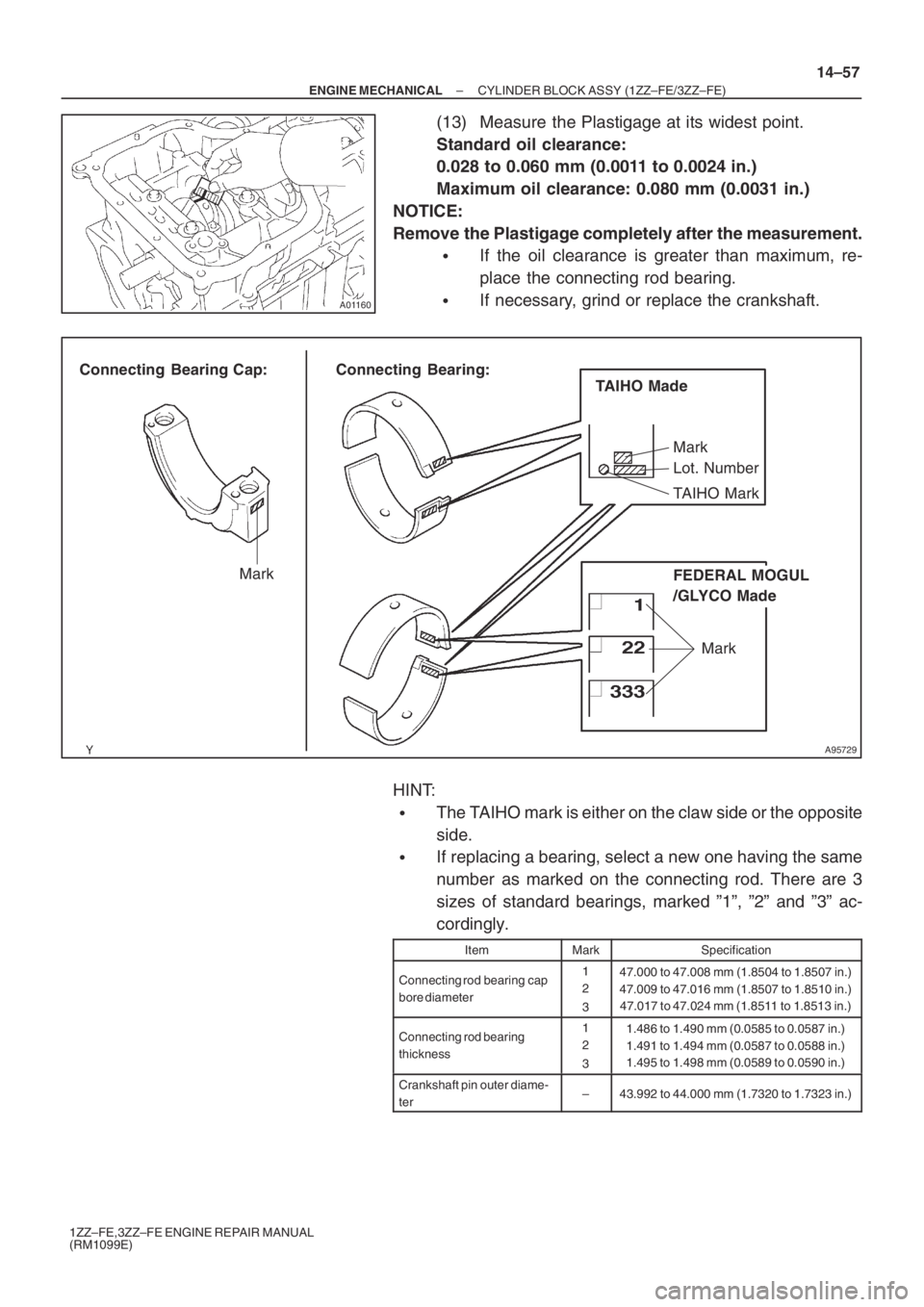
(13) Measure the Plastigage at its widest point.
Standard oil clearance:
0.028 to 0.060 mm (0.0011 to 0.0024 in.)
Maximum oil clearance: 0.080 mm (0.0031 in.)
NOTICE:
Remove the Plastigage completely after the measurement.
�If the oil clearance is greater than maximum, re-
place the connecting rod bearing.
�If necessary, grind or replace the crankshaft.
HINT:
�The TAIHO mark is either on the claw side or the opposite
side.
�If replacing a bearing, select a new one having the same
number as marked on the connecting rod. There are 3
sizes of standard bearings, marked ”1”, ”2” and ”3” ac-
cordingly.
ItemMarkSpecification
Connecting rod bearing cap
bore diameter1
2
347.000 to 47.008 mm (1.8504 to 1.8507 in.)
47.009 to 47.016 mm (1.8507 to 1.8510 in.)
47.017 to 47.024 mm (1.8511 to 1.8513 in.)
Connecting rod bearing
thickness1
2
31.486 to 1.490 mm (0.0585 to 0.0587 in.)
1.491 to 1.494 mm (0.0587 to 0.0588 in.)
1.495 to 1.498 mm (0.0589 to 0.0590 in.)
Crankshaft pin outer diame-
ter–43.992 to 44.000 mm (1.7320 to 1.7323 in.)
Page 5114 of 5135
A01166
A64813
A64814
A64815
A01175
Piston Ring
Expander
14–58
– ENGINE MECHANICALCYLINDER BLOCK ASSY (1ZZ–FE/3ZZ–FE)
1ZZ–FE,3ZZ–FE ENGINE REPAIR MANUAL
(RM1099E)
4. REMOVE CONNECTING ROD SUB–ASSY
(a) Using a ridge reamer, remove all the carbon from the top
of the cylinder.
(b) Push the piston, connecting rod assembly and upper
bearing through the top of the cylinder block.
HINT:
�Keep the bearing, connecting rod and cap together.
�Arrange the piston and connecting rod assemblies in the
correct order.
5. REMOVE CONNECTING ROD BEARING
(a) Remove the connecting rod bearing from the connecting
rod cap.
(b) Remove the connecting rod bearing from the connecting
rod.
6. REMOVE PISTON RING SET
(a) Using a piston ring expander, remove the 2 compression
rings.
(b) Remove the 2 side rails and oil ring by hand.
Page 5119 of 5135
A95733
13.5 mm
(0.531 in.)
A13490
EM0227
– ENGINE MECHANICALCYLINDER BLOCK ASSY (1ZZ–FE/3ZZ–FE)
14–63
1ZZ–FE,3ZZ–FE ENGINE REPAIR MANUAL
(RM1099E)
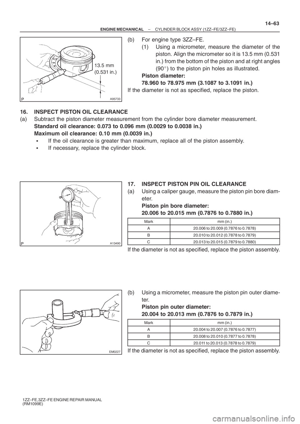
(b) For engine type 3ZZ–FE.
(1) Using a micrometer, measure the diameter of the
piston. Align the micrometer so it is 13.5 mm (0.531
in.) from the bottom of the piston and at right angles
(90�) to the piston pin holes as illustrated.
Piston diameter:
78.960 to 78.975 mm (3.1087 to 3.1091 in.)
If the diameter is not as specified, replace the piston.
16. INSPECT PISTON OIL CLEARANCE
(a) Subtract the piston diameter measurement from the cylinder bore diameter measurement.
Standard oil clearance: 0.073 to 0.096 mm (0.0029 to 0.0038 in.)
Maximum oil clearance: 0.10 mm (0.0039 in.)
�If the oil clearance is greater than maximum, replace all of the piston assembly.
�If necessary, replace the cylinder block.
17. INSPECT PISTON PIN OIL CLEARANCE
(a) Using a caliper gauge, measure the piston pin bore diam-
eter.
Piston pin bore diameter:
20.006 to 20.015 mm (0.7876 to 0.7880 in.)
Markmm (in.)
A20.006 to 20.009 (0.7876 to 0.7878)
B20.010 to 20.012 (0.7878 to 0.7879)
C20.013 to 20.015 (0.7879 to 0.7880)
If the diameter is not as specified, replace the piston assembly.
(b) Using a micrometer, measure the piston pin outer diame-
ter.
Piston pin outer diameter:
20.004 to 20.013 mm (0.7876 to 0.7879 in.)
Markmm (in.)
A20.004 to 20.007 (0.7876 to 0.7877)
B20.008 to 20.010 (0.7877 to 0.7878)
C20.011 to 20.013 (0.7878 to 0.7879)
If the diameter is not as specified, replace the piston assembly.
Page 5120 of 5135
A01185
A64970
Front Mark
Connecting Rod
Small End
Bore Diameter
MarkPiston Pin
Bore Diameter
Mark
Front Mark
Piston:
Connecting Rod:
A01171
14–64
– ENGINE MECHANICALCYLINDER BLOCK ASSY (1ZZ–FE/3ZZ–FE)
1ZZ–FE,3ZZ–FE ENGINE REPAIR MANUAL
(RM1099E)
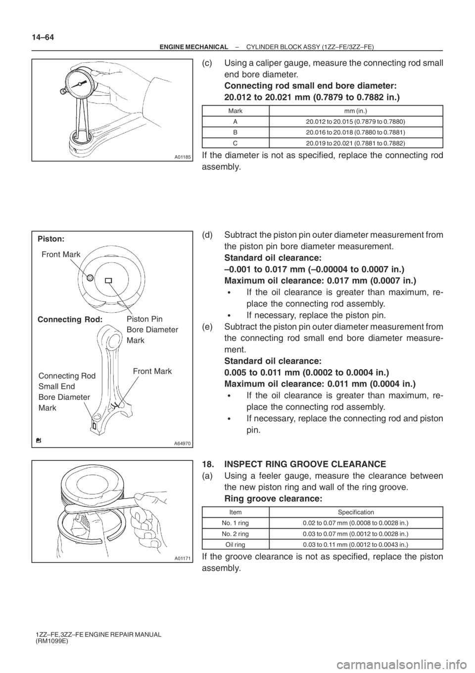
(c) Using a caliper gauge, measure the connecting rod small
end bore diameter.
Connecting rod small end bore diameter:
20.012 to 20.021 mm (0.7879 to 0.7882 in.)
Markmm (in.)
A20.012 to 20.015 (0.7879 to 0.7880)
B20.016 to 20.018 (0.7880 to 0.7881)
C20.019 to 20.021 (0.7881 to 0.7882)
If the diameter is not as specified, replace the connecting rod
assembly.
(d) Subtract the piston pin outer diameter measurement from
the piston pin bore diameter measurement.
Standard oil clearance:
–0.001 to 0.017 mm (–0.00004 to 0.0007 in.)
Maximum oil clearance: 0.017 mm (0.0007 in.)
�If the oil clearance is greater than maximum, re-
place the connecting rod assembly.
�If necessary, replace the piston pin.
(e) Subtract the piston pin outer diameter measurement from
the connecting rod small end bore diameter measure-
ment.
Standard oil clearance:
0.005 to 0.011 mm (0.0002 to 0.0004 in.)
Maximum oil clearance: 0.011 mm (0.0004 in.)
�If the oil clearance is greater than maximum, re-
place the connecting rod assembly.
�If necessary, replace the connecting rod and piston
pin.
18. INSPECT RING GROOVE CLEARANCE
(a) Using a feeler gauge, measure the clearance between
the new piston ring and wall of the ring groove.
Ring groove clearance:
ItemSpecification
No. 1 ring0.02 to 0.07 mm (0.0008 to 0.0028 in.)
No. 2 ring0.03 to 0.07 mm (0.0012 to 0.0028 in.)
Oil ring0.03 to 0.11 mm (0.0012 to 0.0043 in.)
If the groove clearance is not as specified, replace the piston
assembly.
Page 5121 of 5135
A01170
11 0 m m
(4.33 in.)
EM7639
A62804
A62805
– ENGINE MECHANICALCYLINDER BLOCK ASSY (1ZZ–FE/3ZZ–FE)
14–65
1ZZ–FE,3ZZ–FE ENGINE REPAIR MANUAL
(RM1099E)
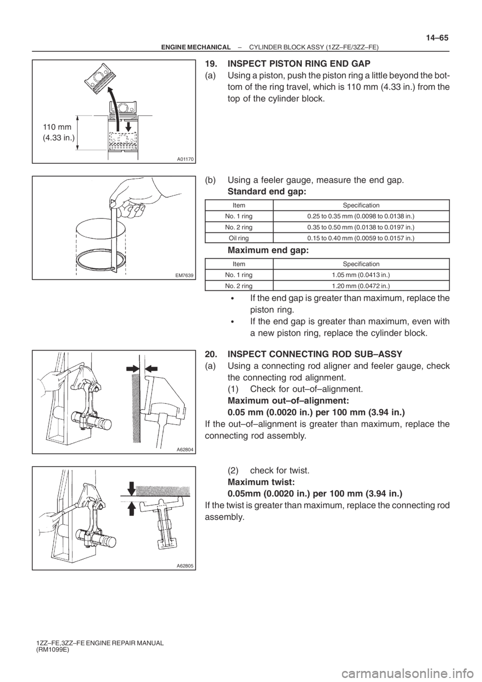
19. INSPECT PISTON RING END GAP
(a) Using a piston, push the piston ring a little beyond the bot-
tom of the ring travel, which is 110 mm (4.33 in.) from the
top of the cylinder block.
(b) Using a feeler gauge, measure the end gap.
Standard end gap:
ItemSpecification
No. 1 ring0.25 to 0.35 mm (0.0098 to 0.0138 in.)
No. 2 ring0.35 to 0.50 mm (0.0138 to 0.0197 in.)
Oil ring0.15 to 0.40 mm (0.0059 to 0.0157 in.)
Maximum end gap:
ItemSpecification
No. 1 ring1.05 mm (0.0413 in.)
No. 2 ring1.20 mm (0.0472 in.)
�If the end gap is greater than maximum, replace the
piston ring.
�If the end gap is greater than maximum, even with
a new piston ring, replace the cylinder block.
20. INSPECT CONNECTING ROD SUB–ASSY
(a) Using a connecting rod aligner and feeler gauge, check
the connecting rod alignment.
(1) Check for out–of–alignment.
Maximum out–of–alignment:
0.05 mm (0.0020 in.) per 100 mm (3.94 in.)
If the out–of–alignment is greater than maximum, replace the
connecting rod assembly.
(2) check for twist.
Maximum twist:
0.05mm (0.0020 in.) per 100 mm (3.94 in.)
If the twist is greater than maximum, replace the connecting rod
assembly.
Page 5122 of 5135
A01470
A64828
ZF6927
ZF6928
14–66
– ENGINE MECHANICALCYLINDER BLOCK ASSY (1ZZ–FE/3ZZ–FE)
1ZZ–FE,3ZZ–FE ENGINE REPAIR MANUAL
(RM1099E)
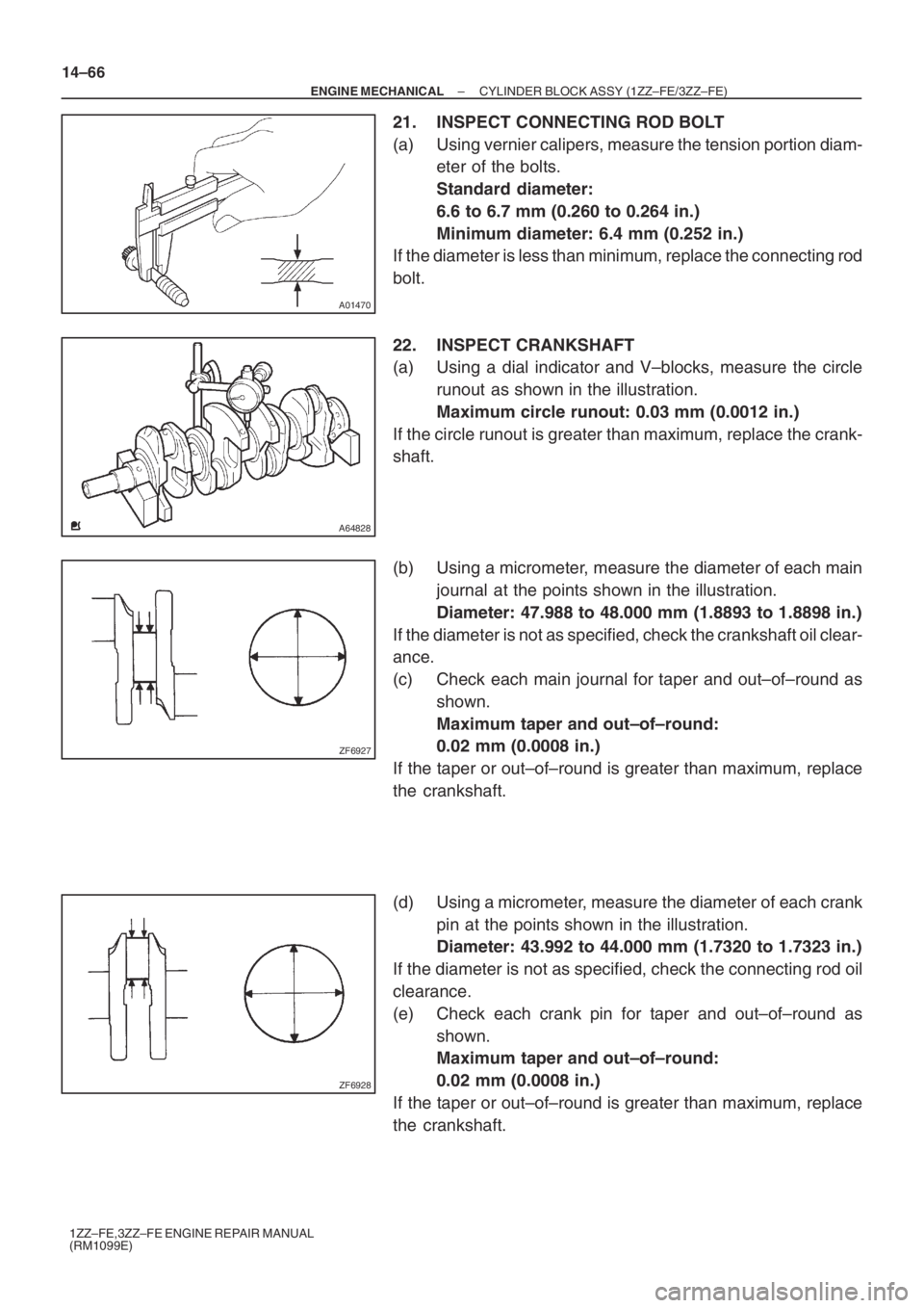
21. INSPECT CONNECTING ROD BOLT
(a) Using vernier calipers, measure the tension portion diam-
eter of the bolts.
Standard diameter:
6.6 to 6.7 mm (0.260 to 0.264 in.)
Minimum diameter: 6.4 mm (0.252 in.)
If the diameter is less than minimum, replace the connecting rod
bolt.
22. INSPECT CRANKSHAFT
(a) Using a dial indicator and V–blocks, measure the circle
runout as shown in the illustration.
Maximum circle runout: 0.03 mm (0.0012 in.)
If the circle runout is greater than maximum, replace the crank-
shaft.
(b) Using a micrometer, measure the diameter of each main
journal at the points shown in the illustration.
Diameter: 47.988 to 48.000 mm (1.8893 to 1.8898 in.)
If the diameter is not as specified, check the crankshaft oil clear-
ance.
(c) Check each main journal for taper and out–of–round as
shown.
Maximum taper and out–of–round:
0.02 mm (0.0008 in.)
If the taper or out–of–round is greater than maximum, replace
the crankshaft.
(d) Using a micrometer, measure the diameter of each crank
pin at the points shown in the illustration.
Diameter: 43.992 to 44.000 mm (1.7320 to 1.7323 in.)
If the diameter is not as specified, check the connecting rod oil
clearance.
(e) Check each crank pin for taper and out–of–round as
shown.
Maximum taper and out–of–round:
0.02 mm (0.0008 in.)
If the taper or out–of–round is greater than maximum, replace
the crankshaft.