Page 5072 of 5135
A76719
A62838SST
A62838SST
A76713
– ENGINE MECHANICALPARTIAL ENGINE ASSY (1ZZ–FE/3ZZ–FE)(From
February, 2004)14–15
AVENSIS REPAIR MANUAL SUPPLEMENT
(RM1098E)
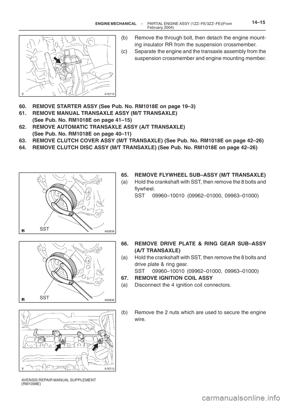
(b) Remove the through bolt, then detach the engine mount-
ing insulator RR from the suspension crossmember.
(c) Separate the engine and the transaxle assembly from the
suspension crossmember and engine mounting member.
60. REMOVE STARTER ASSY (See Pub. No. RM1018E on page 19–3)
61. REMOVE MANUAL TRANSAXLE ASSY (M/T TRANSAXLE)
(See Pub. No. RM1018E on page 41–15)
62. REMOVE AUTOMATIC TRANSAXLE ASSY (A/T TRANSAXLE)
(See Pub. No. RM1018E on page 40–11)
63. REMOVE CLUTCH COVER ASSY (M/T TRANSAXLE) (See Pub. No. RM1018E on page 42–26)
64. REMOVE CLUTCH DISC ASSY (M/T TRANSAXLE) (See Pub. No. RM1018E on page 42–26)
65. REMOVE FLYWHEEL SUB–ASSY (M/T TRANSAXLE)
(a) Hold the crankshaft with SST, then remove the 8 bolts and
flywheel.
SST 09960–10010 (09962–01000, 09963–01000)
66. REMOVE DRIVE PLATE & RING GEAR SUB–ASSY
(A/T TRANSAXLE)
(a) Hold the crankshaft with SST, then remove the 8 bolts and
drive plate & ring gear.
SST 09960–10010 (09962–01000, 09963–01000)
67. REMOVE IGNITION COIL ASSY
(a) Disconnect the 4 ignition coil connectors.
(b) Remove the 2 nuts which are used to secure the engine
wire.
Page 5073 of 5135
A64023
A93668
A64026
A96570
14–16– ENGINE MECHANICALPARTIAL ENGINE ASSY (1ZZ–FE/3ZZ–FE)(From
February, 2004)
AVENSIS REPAIR MANUAL SUPPLEMENT
(RM1098E)
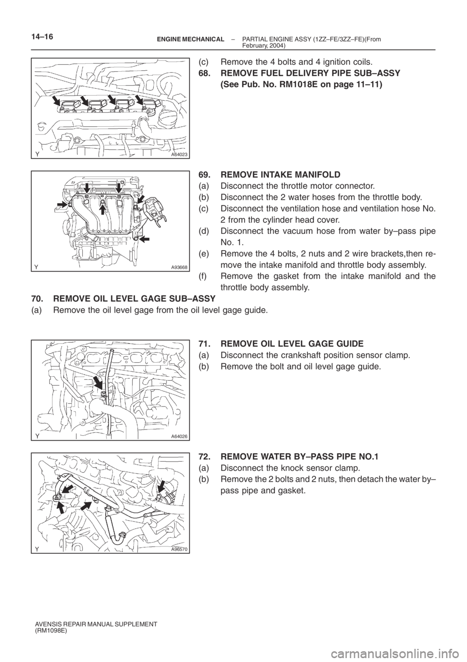
(c) Remove the 4 bolts and 4 ignition coils.
68. REMOVE FUEL DELIVERY PIPE SUB–ASSY
(See Pub. No. RM1018E on page 11–11)
69. REMOVE INTAKE MANIFOLD
(a) Disconnect the throttle motor connector.
(b) Disconnect the 2 water hoses from the throttle body.
(c) Disconnect the ventilation hose and ventilation hose No.
2 from the cylinder head cover.
(d) Disconnect the vacuum hose from water by–pass pipe
No. 1.
(e) Remove the 4 bolts, 2 nuts and 2 wire brackets,then re-
move the intake manifold and throttle body assembly.
(f) Remove the gasket from the intake manifold and the
throttle body assembly.
70. REMOVE OIL LEVEL GAGE SUB–ASSY
(a) Remove the oil level gage from the oil level gage guide.
71. REMOVE OIL LEVEL GAGE GUIDE
(a) Disconnect the crankshaft position sensor clamp.
(b) Remove the bolt and oil level gage guide.
72. REMOVE WATER BY–PASS PIPE NO.1
(a) Disconnect the knock sensor clamp.
(b) Remove the 2 bolts and 2 nuts, then detach the water by–
pass pipe and gasket.
Page 5074 of 5135
A64028
B00084
A76692
A64029
A96566
– ENGINE MECHANICALPARTIAL ENGINE ASSY (1ZZ–FE/3ZZ–FE)(From
February, 2004)14–17
AVENSIS REPAIR MANUAL SUPPLEMENT
(RM1098E)
73. REMOVE WATER INLET
(a) Remove the 2 nuts and water inlet.
74. REMOVE THERMOSTAT
75. REMOVE ENGINE OIL PRESSURE SWITCH ASSY
(See Pub. No. RM1018E on page 17–1)
76. REMOVE CAMSHAFT POSITION SENSOR
(a) Remove the bolt and camshaft position sensor.
77. REMOVE CRANKSHAFT POSITION SENSOR
(a) Remove the 2 bolts and crankshaft position sensor.
78. REMOVE KNOCK SENSOR
(a) Remove the nut and knock sensor.
79. REMOVE V–RIBBED IDLER ASSY NO.1
(a) Remove the nut, bolt, tube and idler.
Page 5078 of 5135
A64059
A96566
A76692
B00084
A64028
– ENGINE MECHANICALPARTIAL ENGINE ASSY (1ZZ–FE/3ZZ–FE)(From
February, 2004)14–21
AVENSIS REPAIR MANUAL SUPPLEMENT
(RM1098E)
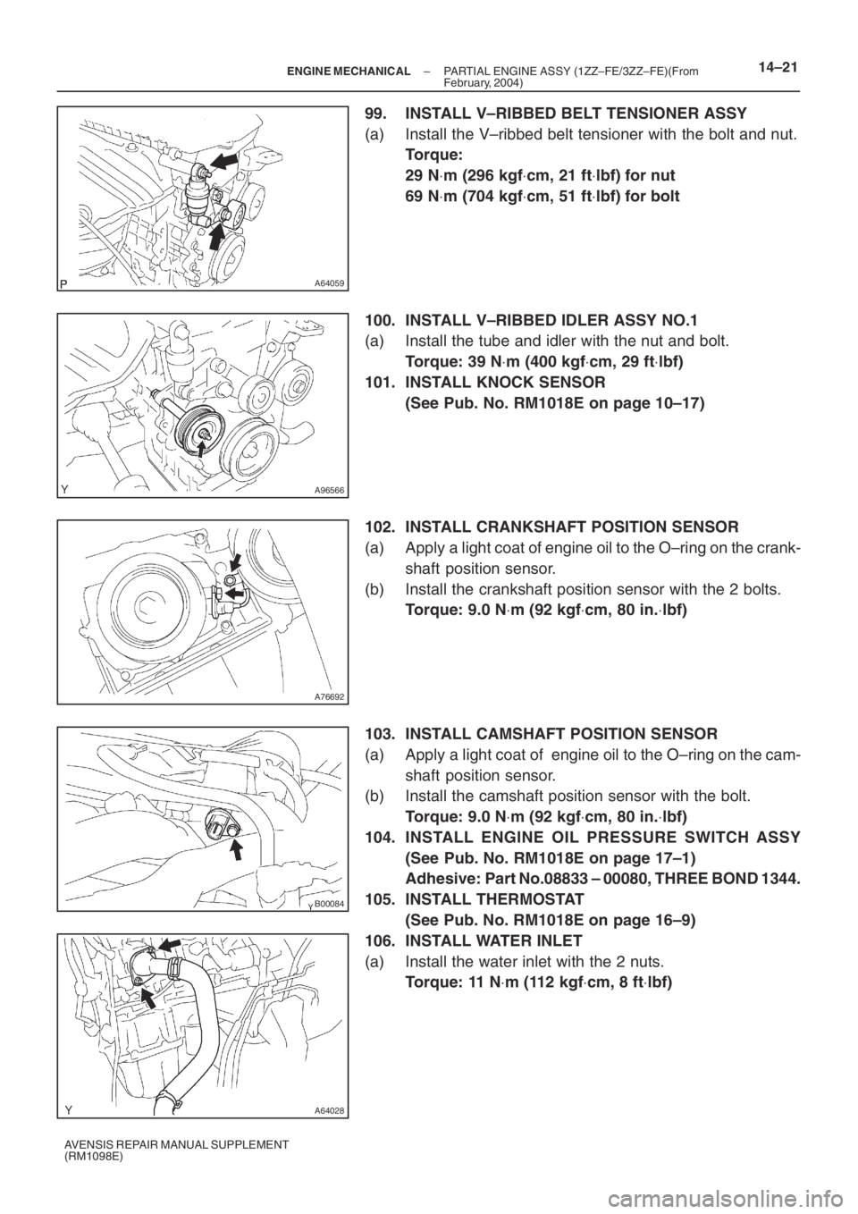
99. INSTALL V–RIBBED BELT TENSIONER ASSY
(a) Install the V–ribbed belt tensioner with the bolt and nut.
Torque:
29 N⋅m (296 kgf⋅cm, 21 ft⋅lbf) for nut
69 N⋅m (704 kgf⋅cm, 51 ft⋅lbf) for bolt
100. INSTALL V–RIBBED IDLER ASSY NO.1
(a) Install the tube and idler with the nut and bolt.
Torque: 39 N⋅m (400 kgf⋅cm, 29 ft⋅lbf)
101. INSTALL KNOCK SENSOR
(See Pub. No. RM1018E on page 10–17)
102. INSTALL CRANKSHAFT POSITION SENSOR
(a) Apply a light coat of engine oil to the O–ring on the crank-
shaft position sensor.
(b) Install the crankshaft position sensor with the 2 bolts.
Torque: 9.0 N⋅m (92 kgf⋅cm, 80 in.⋅lbf)
103. INSTALL CAMSHAFT POSITION SENSOR
(a) Apply a light coat of engine oil to the O–ring on the cam-
shaft position sensor.
(b) Install the camshaft position sensor with the bolt.
Torque: 9.0 N⋅m (92 kgf⋅cm, 80 in.⋅lbf)
104. INSTALL ENGINE OIL PRESSURE SWITCH ASSY
(See Pub. No. RM1018E on page 17–1)
Adhesive: Part No.08833 – 00080, THREE BOND 1344.
105. INSTALL THERMOSTAT
(See Pub. No. RM1018E on page 16–9)
106. INSTALL WATER INLET
(a) Install the water inlet with the 2 nuts.
Torque: 11 N⋅m (112 kgf⋅cm, 8 ft⋅lbf)
Page 5079 of 5135
A96570
A64026
A93668
A64023
A76713
14–22– ENGINE MECHANICALPARTIAL ENGINE ASSY (1ZZ–FE/3ZZ–FE)(From
February, 2004)
AVENSIS REPAIR MANUAL SUPPLEMENT
(RM1098E)
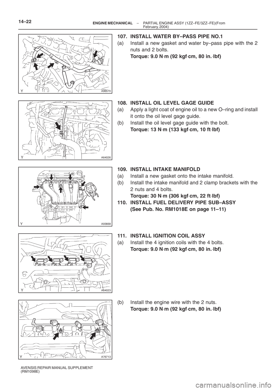
107. INSTALL WATER BY–PASS PIPE NO.1
(a) Install a new gasket and water by–pass pipe with the 2
nuts and 2 bolts.
Torque: 9.0 N⋅m (92 kgf⋅cm, 80 in.⋅lbf)
108. INSTALL OIL LEVEL GAGE GUIDE
(a) Apply a light coat of engine oil to a new O–ring and install
it onto the oil level gage guide.
(b) Install the oil level gage guide with the bolt.
Torque: 13 N⋅m (133 kgf⋅cm, 10 ft⋅lbf)
109. INSTALL INTAKE MANIFOLD
(a) Install a new gasket onto the intake manifold.
(b) Install the intake manifold and 2 clamp brackets with the
2 nuts and 4 bolts.
Torque: 30 N⋅m (306 kgf⋅cm, 22 ft⋅lbf)
110. INSTALL FUEL DELIVERY PIPE SUB–ASSY
(See Pub. No. RM1018E on page 11–11)
111. INSTALL IGNITION COIL ASSY
(a) Install the 4 ignition coils with the 4 bolts.
Torque: 9.0 N⋅m (92 kgf⋅cm, 80 in.⋅lbf)
(b) Install the engine wire with the 2 nuts.
Torque: 9.0 N⋅m (92 kgf⋅cm, 80 in.⋅lbf)
Page 5083 of 5135
A93669
14–26–
ENGINE MECHANICAL PARTIAL ENGINE ASSY (1ZZ–FE/3ZZ–FE)(From
February, 2004)
AVENSIS REPAIR MANUAL SUPPLEMENT
(RM1098E)
137. INSTALL BATTERY
Torque:
5.0 N ⋅m (51 kgf ⋅cm, 44 in. ⋅lbf) for bolt
3.5 N ⋅m (36 kgf ⋅cm, 31 in. ⋅lbf) for nut
138. INSTALL RADIATOR SUPPORT NO.1
(a) Install the 2 radiator supports with the 2 bolts.
Torque: 19 N ⋅m (194 kgf ⋅cm, 14 ft ⋅lbf)
139. INSTALL AIR CLEANER CASE SUB–ASSY
(a) Install the air cleaner case with the 3 bolts.
Torque: 5.0 N ⋅m (51 kgf ⋅cm, 44 in. ⋅lbf)
140. INSTALL AIR CLEANER ASSEMBLY WITH HOSE (See page 10–6)
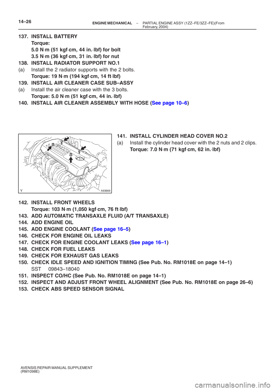
141. INSTALL CYLINDER HEAD COVER NO.2
(a) Install the cylinder head cover with the 2 nuts and 2 clips.
Torque: 7.0 N ⋅m (71 kgf ⋅cm, 62 in. ⋅lbf)
142. INSTALL FRONT WHEELS
Torque: 103 N ⋅m (1,050 kgf ⋅cm, 76 ft ⋅lbf)
143. ADD AUTOMATIC TRANSAXLE FLUID (A/T TRANSAXLE)
144. ADD ENGINE OIL
145. ADD ENGINE COOLANT (See page 16–5)
146. CHECK FOR ENGINE OIL LEAKS
147. CHECK FOR ENGINE COOLANT LEAKS (See page 16–1)
148. CHECK FOR FUEL LEAKS
149. CHECK FOR EXHAUST GAS LEAKS
150. CHECK IDLE SPEED AND IGNITION TIMING (See Pub. No. RM1018E on page 14–1)
SST 09843–18040
151. INSPECT CO/HC (See Pub. No. RM1018E on page 14–1)
152. INSPECT AND ADJUST FRONT WHEEL ALIGNMENT (See Pub. No. RM1018E on page \
26–6)
153. CHECK ABS SPEED SENSOR SIGNAL
Page 5108 of 5135
A95722
Matchmark
A95724
SST
14–52
– ENGINE MECHANICALCYLINDER BLOCK ASSY (1ZZ–FE/3ZZ–FE)
1ZZ–FE,3ZZ–FE ENGINE REPAIR MANUAL
(RM1099E)
(d) Using a dial indicator, measure the thrust clearance of the
No. 1 and No. 4 cylinders while moving the connecting rod
back and forth.
Standard thrust clearance:
0.160 to 0.342 mm (0.0063 to 0.0135 in.)
Maximum thrust clearance:
0.342 mm (0.0135 in.)
�If the thrust clearance is greater than maximum, re-
place the connecting rod.
�If necessary, replace the crankshaft.
3. INSPECT CONNECTING ROD OIL CLEARANCE
(a) Turn the crankshaft and set the No. 1 cylinder to the TDC/
compression.
(b) Measure the oil clearance of the No. 2 and No. 3 cylin-
ders.
NOTICE:
Do not turn the crankshaft during the measurement.
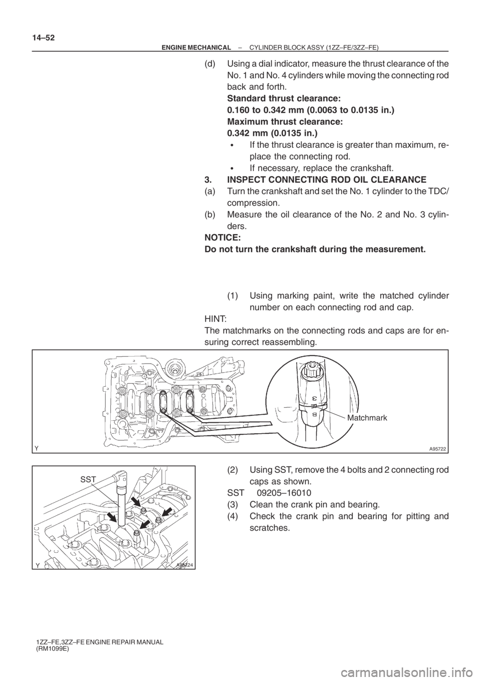
(1) Using marking paint, write the matched cylinder
number on each connecting rod and cap.
HINT:
The matchmarks on the connecting rods and caps are for en-
suring correct reassembling.
(2) Using SST, remove the 4 bolts and 2 connecting rod
caps as shown.
SST 09205–16010
(3) Clean the crank pin and bearing.
(4) Check the crank pin and bearing for pitting and
scratches.
Page 5109 of 5135
A95725
Plastigage
A95726
Front Mark
A95724
SST
A65715
Paint Mark90� Engine
Front
A95724
SST
– ENGINE MECHANICALCYLINDER BLOCK ASSY (1ZZ–FE/3ZZ–FE)
14–53
1ZZ–FE,3ZZ–FE ENGINE REPAIR MANUAL
(RM1099E)
(5) Lay a strip of Plastigage across the crank pin.
(6) Check that the front marks of the 2connecting rod
caps are facing in the correct direction.
(7) Apply a light coat of engine oil to the threads and un-
der the heads of the connecting rod cap bolts.
(8) Using SST, tighten the 2 bolts in several passes to
the specified torque.
SST 09205–16010
Torque: 20 N⋅m (204 kgf⋅cm, 15 ft⋅lbf)
(9) Mark the front of the connecting cap bolts with paint.
(10) Retighten the cap bolts by an additional 90� as
shown in the illustration.
(11) Check that the crankshaft turns smoothly.
(12) Remove the 4 bolts and 2 connecting rod caps.