Page 193 of 4555
![NISSAN X-TRAIL 2005 Service Repair Manual NOISE, VIBRATION AND HARSHNESS (NVH) TROUBLESHOOTING
EM-139
[YD22DDTi]
C
D
E
F
G
H
I
J
K
L
MA
EM
Use the Chart Below to Help You Find the Cause of the Symptom.EBS00LR9
1. Locate the area where noise](/manual-img/5/57403/w960_57403-192.png "NISSAN X-TRAIL 2005 Service Repair Manual NOISE, VIBRATION AND HARSHNESS (NVH) TROUBLESHOOTING
EM-139
[YD22DDTi]
C
D
E
F
G
H
I
J
K
L
MA
EM
Use the Chart Below to Help You Find the Cause of the Symptom.EBS00LR9
1. Locate the area where noise")
NOISE, VIBRATION AND HARSHNESS (NVH) TROUBLESHOOTING
EM-139
[YD22DDTi]
C
D
E
F
G
H
I
J
K
L
MA
EM
Use the Chart Below to Help You Find the Cause of the Symptom.EBS00LR9
1. Locate the area where noise occurs.
2. Confirm the type of noise.
3. Specify the operating condition of engine.
4. Check specified noise source.
If necessary, repair or replace these parts.
A: Closely related B: Related C: Sometimes related —: Not relatedLocation
of noiseType of
noiseOperating condition of engine
Source of
noiseCheck itemRefer-
ence page Before
warm-
upAfter
warm-
upWhen
start-
ingWhen
idlingWhen
racingWhile
driving
Top of
engine
Rocker
cover
Cylinder
headTicking or
clickingCA—AB—Tappet
noiseValve clearanceEM-185
Rattle C A — A B CCamshaft
bearing
noiseCamshaft oil clearance
Camshaft runoutEM-182EM-181
Crank-
shaft pul-
ley
Cylinder
block
(Side of
engine)
Oil panSlap or
knock—A—BB—Piston pin
noisePiston to piston pin
clearance
Connecting rod bush-
ing oil clearanceEM-246
EM-248
Slap or
rapA ——BBAPiston
slap noisePiston to cylinder bore
clearance
Piston ring side clear-
ance
Piston ring end gap
Connecting rod bend
and torsionEM-250EM-247
EM-247
EM-248
Knock A B C B B BConnect-
ing rod
bearing
noiseConnecting rod bush-
ing oil clearance
Connecting rod bear-
ing oil clearance (Big
end)EM-248EM-252
Knock A B — A B CMain
bearing
noiseMain bearing oil clear-
ance
Crankshaft runoutEM-253EM-252
Front of
engine
Timing
chain
caseTapping or
tickingA A —BBBTiming
chain and
chain ten-
sioner
noiseTiming chain cracks
and wear
Timing chain tensioner
operationEM-193
EM-198
Front of
engineSqueak-
ing or fizz-
ingAB—B—CDrive belts
(Sticking
or slip-
ping)Drive belts deflection
EM-140
CreakingA B ABABDrive belts
(Slipping)Idler pulley bearing
operation
Squall
CreakA B —BABWater
pump
noiseWater pump operationCO-43,
"WATER
PUMP"
Page 194 of 4555
![NISSAN X-TRAIL 2005 Service Repair Manual EM-140
[YD22DDTi]
DRIVE BELTS
DRIVE BELTSPFP:02117
Checking Drive BeltsEBS00LRA
�Before inspecting engine, make sure engine has cooled down;
wait approximately 30 minutes after engine has been stopp](/manual-img/5/57403/w960_57403-193.png "NISSAN X-TRAIL 2005 Service Repair Manual EM-140
[YD22DDTi]
DRIVE BELTS
DRIVE BELTSPFP:02117
Checking Drive BeltsEBS00LRA
�Before inspecting engine, make sure engine has cooled down;
wait approximately 30 minutes after engine has been stopp")
EM-140
[YD22DDTi]
DRIVE BELTS
DRIVE BELTSPFP:02117
Checking Drive BeltsEBS00LRA
�Before inspecting engine, make sure engine has cooled down;
wait approximately 30 minutes after engine has been stopped.
�Visually inspect all belts for wear, damage or cracks on contact-
ing surfaces and edge areas.
�When measuring deflection, apply 98 N (10 kg, 22 lb) at the
marked point ( ).
CAUTION:
�When checking belt deflection immediately after installa-
tion, first adjust it to the specified value. Then, after turn-
ing crankshaft two turns or more, re-adjust to the
specified value to avoid variation in deflection between
pulleys.
�Tighten idler pulley lock nut by hand and measure deflection without looseness.
Belt Deflection:
*: When engine is cold.
Tension AdjustmentEBS00LRB
�Adjust belts with the parts shown below.
CAUTION:
�When a new belt is installed as a replacement, adjust it to the specified value under “New” value
because of insufficient adaptability with pulley grooves.
�If the belt deflection of the current belt is out of the “Limit for re-adjusting”, adjust to the
“Adjusted” value.
�When checking belt deflection immediately after installation, first adjust it to the specified value.
Then, after turning crankshaft two turns or more, re-adjust it to the specified value to avoid vari-
ation in deflection between pulleys.
�Make sure the belts are fully fitted into the pulley grooves during installation.
�Handle with care to avoid smearing the belts with engine oil or engine coolant.
�Do not twist or bend the belts with strong force.
PBIC1251E
Applied beltBelt deflection with 98 N (10 kg, 22 lb) force applied* mm (in)
New Adjusted Limit for re-adjusting
A/C compressor belt 4 - 5 (0.16 - 0.20) 6 - 7 (0.24 - 0.28) 8.5 (0.335)
Alternator and water pump belt 9.0 - 10.5 (0.354 - 0.413) 11.0 - 12.5 (0.433 - 0.492) 16.5 (0.650)
Applied belt Belt adjustment method
A/C compressor belt Adjusting bolt on idler pulley
Alternator and water pump belt Adjusting bolt on alternator
Page 195 of 4555
![NISSAN X-TRAIL 2005 Service Repair Manual DRIVE BELTS
EM-141
[YD22DDTi]
C
D
E
F
G
H
I
J
K
L
MA
EM
A/C COMPRESSOR BELT
1. Remove RH engine undercover.
2. Loosen idler pulley lock nut (A).
3. Turn adjusting bolt (B) to adjust. Refer to EM-140](/manual-img/5/57403/w960_57403-194.png "NISSAN X-TRAIL 2005 Service Repair Manual DRIVE BELTS
EM-141
[YD22DDTi]
C
D
E
F
G
H
I
J
K
L
MA
EM
A/C COMPRESSOR BELT
1. Remove RH engine undercover.
2. Loosen idler pulley lock nut (A).
3. Turn adjusting bolt (B) to adjust. Refer to EM-140")
DRIVE BELTS
EM-141
[YD22DDTi]
C
D
E
F
G
H
I
J
K
L
MA
EM
A/C COMPRESSOR BELT
1. Remove RH engine undercover.
2. Loosen idler pulley lock nut (A).
3. Turn adjusting bolt (B) to adjust. Refer to EM-140, "
Checking
Drive Belts" .
4. Tighten lock nut (A).
ALTERNATOR AND WATER PUMP BELT
1. Loosen adjusting lock nut (C).
2. Loosen alternator fixing bolts (D) (each on front and rear).
3. Turn adjusting bolt (E) to adjust. Refer to EM-140, "
Checking Drive Belts" .
4. Tighten nut (C) and bolt (D) in this order.
Removal and InstallationEBS00LRC
REMOVAL
1. Loosen each belt. Refer to EM-140, "Tension Adjustment" .
2. Remove A/C compressor belt. Refer to EM-141, "
A/C COMPRESSOR BELT" .
3. Remove alternator and water pump belt. Refer to EM-141, "
ALTERNATOR AND WATER PUMP BELT" .
INSTALLATION
1. Install each belt on pulley in the reverse order of removal.
2. Adjust belt tension. Refer to EM-140, "
Tension Adjustment" .
3. Tighten nuts and bolts provided for adjustment to the specified torque.
4. Make sure again that each belt tension is as specified.Nut A:
: 35 N·m (3.6 kg-m, 26 ft-lb)
PBIC1252E
Nut C:
: 21.5 N·m (2.2 kg-m, 16 ft-lb)
Bolt D:
: 50.5 N·m (5.2 kg-m, 37 ft-lb)
Page 198 of 4555
![NISSAN X-TRAIL 2005 Service Repair Manual EM-144
[YD22DDTi]
CHARGE AIR COOLER
CHARGE AIR COOLERPFP:14461
Removal and InstallationEBS00LRE
REMOVAL
1. Remove charge air cooler cover.
2. Disconnect harness connector from turbocharger boost con](/manual-img/5/57403/w960_57403-197.png "NISSAN X-TRAIL 2005 Service Repair Manual EM-144
[YD22DDTi]
CHARGE AIR COOLER
CHARGE AIR COOLERPFP:14461
Removal and InstallationEBS00LRE
REMOVAL
1. Remove charge air cooler cover.
2. Disconnect harness connector from turbocharger boost con")
EM-144
[YD22DDTi]
CHARGE AIR COOLER
CHARGE AIR COOLERPFP:14461
Removal and InstallationEBS00LRE
REMOVAL
1. Remove charge air cooler cover.
2. Disconnect harness connector from turbocharger boost control solenoid valve.
3. Remove air inlet tube and air inlet hose.
�Add marks as necessary for easier installation.
4. Remove charge air cooler.
5. Remove air inlet tube from charge air cooler.
6. Remove turbocharger boost control solenoid valve if necessary.
CAUTION:
When removing charge air cooler, close opening on turbocharger and on intake manifold with shop
cloth or other suitable material.
INSPECTION AFTER REMOVAL
Check air passages of charge air cooler core and fins for clogging, leaks or deformation. Clean or replace
charge air cooler if necessary.
�Be careful not to deform core fins.
�For cleaning procedure of charge air cooler core, refer to CO-36, "Checking Radiator".
INSTALLATION
Note the following, and install in the reverse order of removal.
�Pay attention to identification mark color and direction when installing air inlet hose.
1. Charge air cooler cover 2. Charge air cooler 3. Gasket
4. Air inlet tube 5. Clamp 6. Air inlet hose
7. Bottom bracket 8. Turbocharger boost control solenoid
valve
PBIC2580E
Page 201 of 4555
![NISSAN X-TRAIL 2005 Service Repair Manual INTAKE MANIFOLD
EM-147
[YD22DDTi]
C
D
E
F
G
H
I
J
K
L
MA
EM
5. Remove exhaust manifold insulator. Refer to EM-151, "EXHAUST MANIFOLD AND TURBOCHARGER" .
6. Disconnect harness connector from EGR volu](/manual-img/5/57403/w960_57403-200.png "NISSAN X-TRAIL 2005 Service Repair Manual INTAKE MANIFOLD
EM-147
[YD22DDTi]
C
D
E
F
G
H
I
J
K
L
MA
EM
5. Remove exhaust manifold insulator. Refer to EM-151, \"EXHAUST MANIFOLD AND TURBOCHARGER\" .
6. Disconnect harness connector from EGR volu")
INTAKE MANIFOLD
EM-147
[YD22DDTi]
C
D
E
F
G
H
I
J
K
L
MA
EM
5. Remove exhaust manifold insulator. Refer to EM-151, "EXHAUST MANIFOLD AND TURBOCHARGER" .
6. Disconnect harness connector from EGR volume control valve and water hoses.
7. Disconnect heater hose.
8. Remove EGR cooler.
9. Remove injection tube center. Refer to EM-167, "
Removal and Installation" .
CAUTION:
Be careful not to spill fuel in the engine component.
10. Remove water pipe.
11. Remove fuel hoses and fuel gallery.
�To prevent fuel from flowing out, plug the opening of the hose with plug after disconnection.
CAUTION:
Be careful not to spill fuel in the engine component.
12. Loosen bolts and nuts in reverse order of that shown in the fig-
ure, and remove intake manifold.
CAUTION:
Cover engine openings to avoid entry of foreign materials.
13. Remove EGR volume control valve from intake manifold.
CAUTION:
�Handle with care avoiding any shocks.
�Do not disassemble.
INSPECTION AFTER REMOVAL
Surface Distortion
�Check distortion on the mounting surface with a straightedge
and feeler gauge.
�If it exceeds the limit, replace intake manifold.
INSTALLATION
Following instructions below, install in the reverse order of removal.
1. Install EGR volume control valve.
PBIC0676E
Limit : 0.1 mm (0.004 in)
PBIC0677E
Page 202 of 4555
EM-148
[YD22DDTi]
INTAKE MANIFOLD
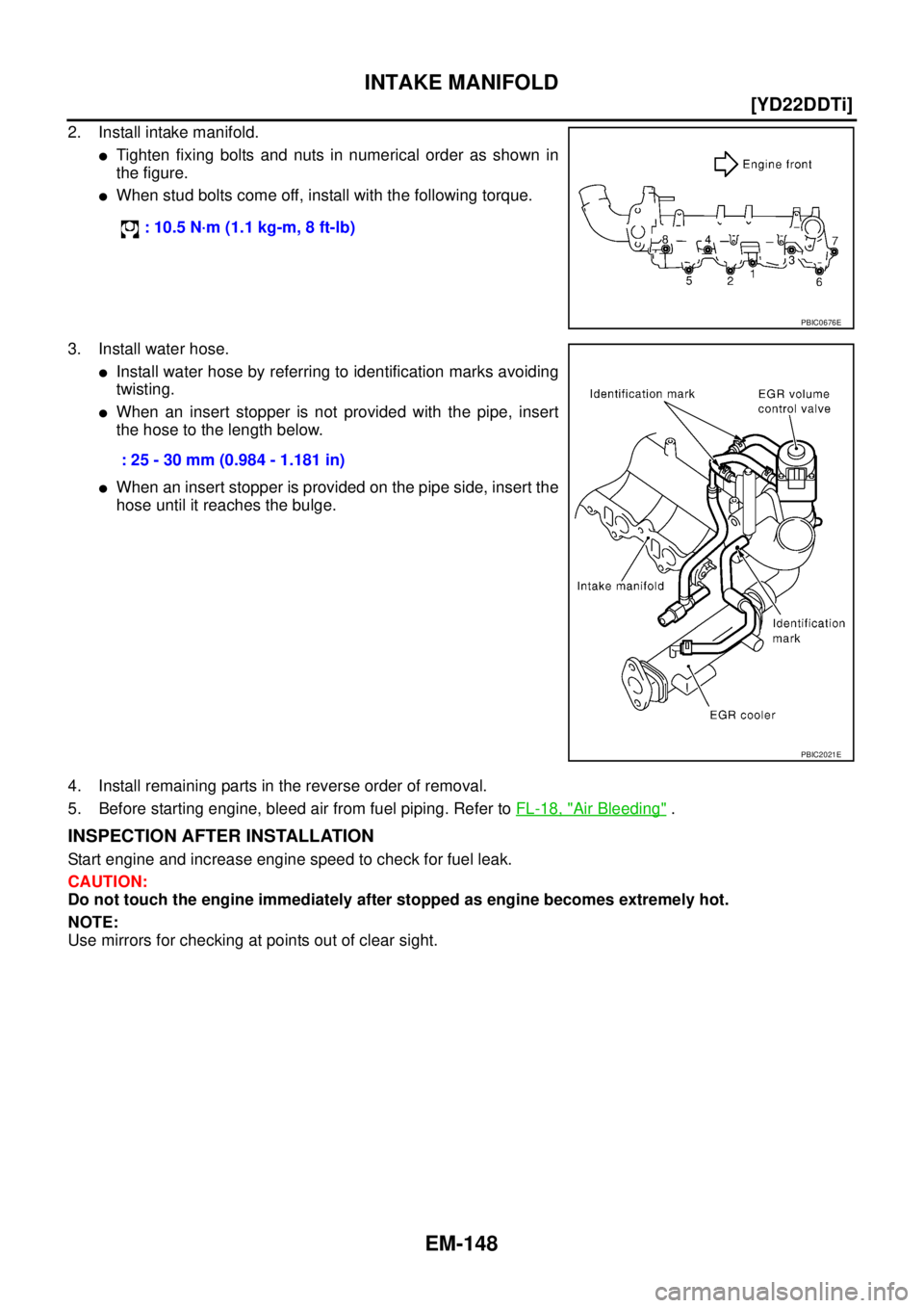
2. Install intake manifold.
�Tighten fixing bolts and nuts in numerical order as shown in
the figure.
�When stud bolts come off, install with the following torque.
3. Install water hose.
�Install water hose by referring to identification marks avoiding
twisting.
�When an insert stopper is not provided with the pipe, insert
the hose to the length below.
�When an insert stopper is provided on the pipe side, insert the
hose until it reaches the bulge.
4. Install remaining parts in the reverse order of removal.
5. Before starting engine, bleed air from fuel piping. Refer to FL-18, "
Air Bleeding" .
INSPECTION AFTER INSTALLATION
Start engine and increase engine speed to check for fuel leak.
CAUTION:
Do not touch the engine immediately after stopped as engine becomes extremely hot.
NOTE:
Use mirrors for checking at points out of clear sight. : 10.5 N·m (1.1 kg-m, 8 ft-lb)
PBIC0676E
: 25 - 30 mm (0.984 - 1.181 in)
PBIC2021E
Page 206 of 4555
![NISSAN X-TRAIL 2005 Service Repair Manual EM-152
[YD22DDTi]
EXHAUST MANIFOLD AND TURBOCHARGER
12. Remove turbocharger insulator.
13. Remove oil feed tube.
14. Loosen exhaust manifold mounting nuts in reverse order in the
figure.
15. Rotate](/manual-img/5/57403/w960_57403-205.png "NISSAN X-TRAIL 2005 Service Repair Manual EM-152
[YD22DDTi]
EXHAUST MANIFOLD AND TURBOCHARGER
12. Remove turbocharger insulator.
13. Remove oil feed tube.
14. Loosen exhaust manifold mounting nuts in reverse order in the
figure.
15. Rotate")
EM-152
[YD22DDTi]
EXHAUST MANIFOLD AND TURBOCHARGER
12. Remove turbocharger insulator.
13. Remove oil feed tube.
14. Loosen exhaust manifold mounting nuts in reverse order in the
figure.
15. Rotate exhaust manifold and turbocharger assembly so that the rear side (EGR cooler mounting side)
faces upward. And then pull out the assembly from between the engine and the A/C piping.
CAUTION:
Be careful not to deform each turbocharger piping when pulling out the assembly.
16. Remove exhaust manifold gasket.
CAUTION:
Cover engine openings to avoid entry of foreign materials.
INSTALLATION
�When a stud bolt is pulled out, tighten it to the following torque:
�Tighten the exhaust manifold mounting nuts in the following procedure:
1. Install gasket so that the alignment protrusion faces the No. 4 port. Refer to EM-151, "
Removal and Instal-
lation" .
2. Tighten the nuts in order specified in the figure.
3. Re-tighten the nuts 1 to 4.
4. Install in the reverse order of removal.
INSPECTION AFTER INSTALLATION
Start engine and raise engine speed to check no exhaust gas and engine oil leaks.
JEM266G
: 14.7 N·m (1.5 kg-m, 11ft-lb)
JEM266G
Page 207 of 4555
EXHAUST MANIFOLD AND TURBOCHARGER
EM-153
[YD22DDTi]
C
D
E
F
G
H
I
J
K
L
MA
EM
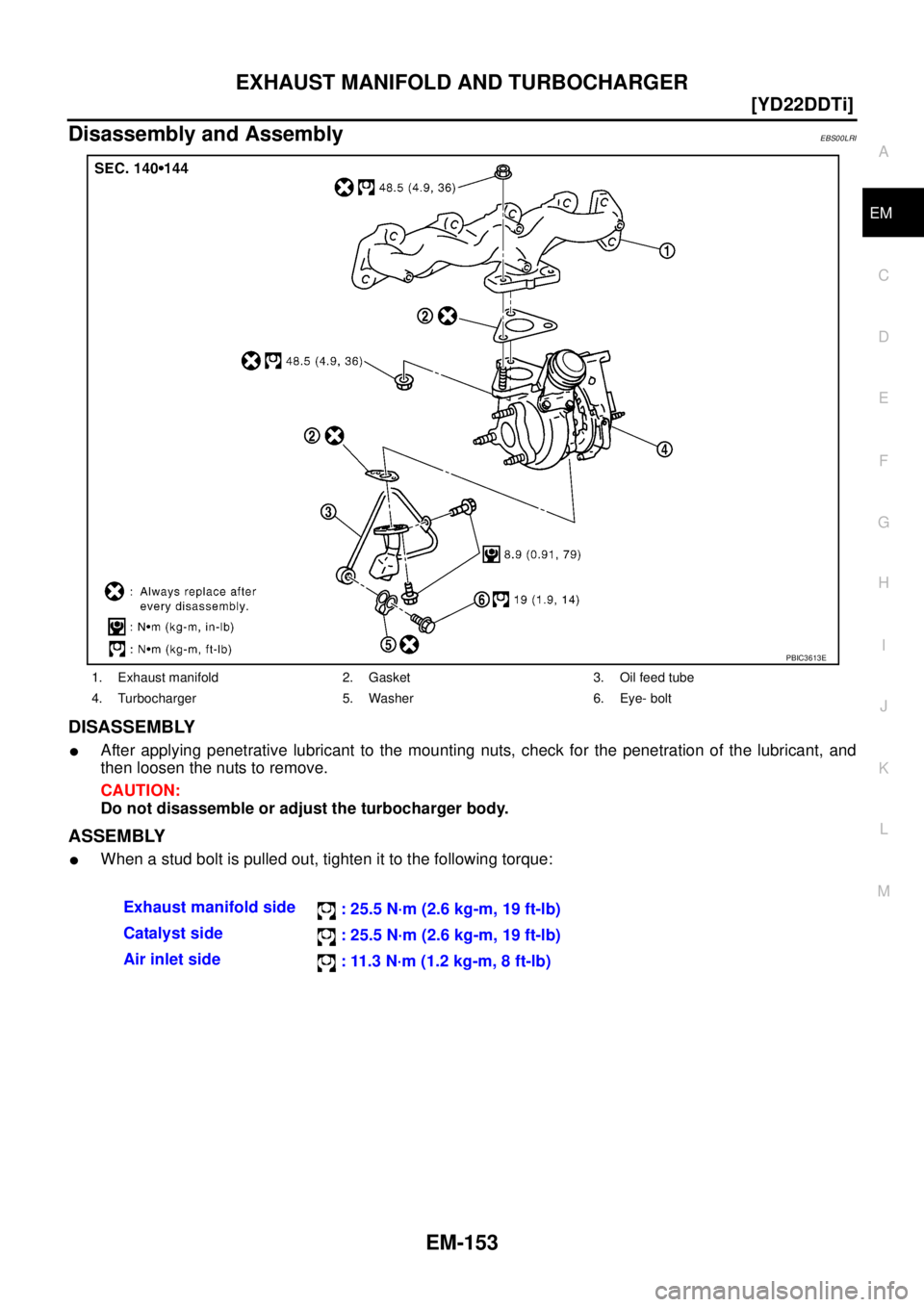
Disassembly and AssemblyEBS00LRI
DISASSEMBLY
�After applying penetrative lubricant to the mounting nuts, check for the penetration of the lubricant, and
then loosen the nuts to remove.
CAUTION:
Do not disassemble or adjust the turbocharger body.
ASSEMBLY
�When a stud bolt is pulled out, tighten it to the following torque:
1. Exhaust manifold 2. Gasket 3. Oil feed tube
4. Turbocharger 5. Washer 6. Eye- bolt
PBIC3613E
Exhaust manifold side
: 25.5 N·m (2.6 kg-m, 19 ft-lb)
Catalyst side
: 25.5 N·m (2.6 kg-m, 19 ft-lb)
Air inlet side
: 11.3 N·m (1.2 kg-m, 8 ft-lb)