Page 208 of 4555
![NISSAN X-TRAIL 2005 Service Repair Manual EM-154
[YD22DDTi]
EXHAUST MANIFOLD AND TURBOCHARGER
INSPECTION AFTER DISASSEMBLY
Surface Distortion
�Check the distortion on the mounting surface in the six directions
using a straightedge and a fee](/manual-img/5/57403/w960_57403-207.png "NISSAN X-TRAIL 2005 Service Repair Manual EM-154
[YD22DDTi]
EXHAUST MANIFOLD AND TURBOCHARGER
INSPECTION AFTER DISASSEMBLY
Surface Distortion
�Check the distortion on the mounting surface in the six directions
using a straightedge and a fee")
EM-154
[YD22DDTi]
EXHAUST MANIFOLD AND TURBOCHARGER
INSPECTION AFTER DISASSEMBLY
Surface Distortion
�Check the distortion on the mounting surface in the six directions
using a straightedge and a feeler gauge.
�If it exceeds the limit, replace exhaust manifold.
TurbochargerEBS00LRJ
CAUTION:
When the compressor wheel turbine, wheel or rotor shaft is damaged, remove all the fragments and
foreign matter left in the following passages in order to prevent a secondary malfunction:
ROTOR SHAFT CLEARANCE
�Make sure that the rotor shaft rotates smoothly without any
resistance when it is rotated by your fingertips.
�Make sure that the rotor shaft is not loose when it is moved ver-
tically or horizontally.
�Measure looseness with a dial indicator inserting its measuring
rod through oil drain hole of turbocharger.
�Replace turbocharger if out of standard.Limit : 0.3 mm (0.012 in)
JEM267G
PBIC2532E
Suction side : Between turbocharger and air cleaner
Exhaust side : Between turbocharger and catalyst
Standard : 0.086 - 0.117 mm (0.0034 - 0.0046 in)
PBIC0727E
Page 210 of 4555
![NISSAN X-TRAIL 2005 Service Repair Manual EM-156
[YD22DDTi]
EXHAUST MANIFOLD AND TURBOCHARGER
TROUBLE DIAGNOSIS OF TURBOCHARGER
Preliminary check:
�Make sure that the engine oil level is between “MIN” and “MAX” of the oil level gaug](/manual-img/5/57403/w960_57403-209.png "NISSAN X-TRAIL 2005 Service Repair Manual EM-156
[YD22DDTi]
EXHAUST MANIFOLD AND TURBOCHARGER
TROUBLE DIAGNOSIS OF TURBOCHARGER
Preliminary check:
�Make sure that the engine oil level is between “MIN” and “MAX” of the oil level gaug")
EM-156
[YD22DDTi]
EXHAUST MANIFOLD AND TURBOCHARGER
TROUBLE DIAGNOSIS OF TURBOCHARGER
Preliminary check:
�Make sure that the engine oil level is between “MIN” and “MAX” of the oil level gauge. (When engine oil
amount is more than “MAX”, engine oil flows into the inlet duct through blow-by gas passage, and turbo-
charger is misjudged malfunction.)
�Ask the customer if he/she always runs the vehicle in idle engine speed to cool the engine oil down after
driving.
�Replace the turbocharger assembly when any malfunction is found after unit inspections specified in the
table below.
�If no malfunction is found after the unit inspections, judge that the turbocharger body has no malfunction.
Check the other parts again.
A: Large possibility
B: Medium possibility
C: Small possibilityInspection item Inspection resultSymptom
(when each inspection item meets each inspection result)
Engine oil
leakageSmoke NoiseInsufficient power/accel-
eration malfunction
Turbine wheelEngine oil leaks C A C C
Carbon is accumulated C A B B
Friction with housing C B A B
Blades are bent or broken — — A A
Compressor wheelInside the air inlet is seriously con-
taminated by engine oil.BB— —
Friction with housing C B A B
Blades are bent or broken — — A A
After checking both turbine and
compressor, inspect rotor shaft
end play.There is resistance when the rotor
shaft is rotated by your fingertips.—CC B
The rotor shaft sometimes does not
rotate by your fingertips.——— A
There is too much play in the bear-
ing.CCB C
Oil return portCarbon or sludge is accumulated in
the waste oil hole.CAC C
Page 215 of 4555
OIL PAN AND OIL STRAINER
EM-161
[YD22DDTi]
C
D
E
F
G
H
I
J
K
L
MA
EM
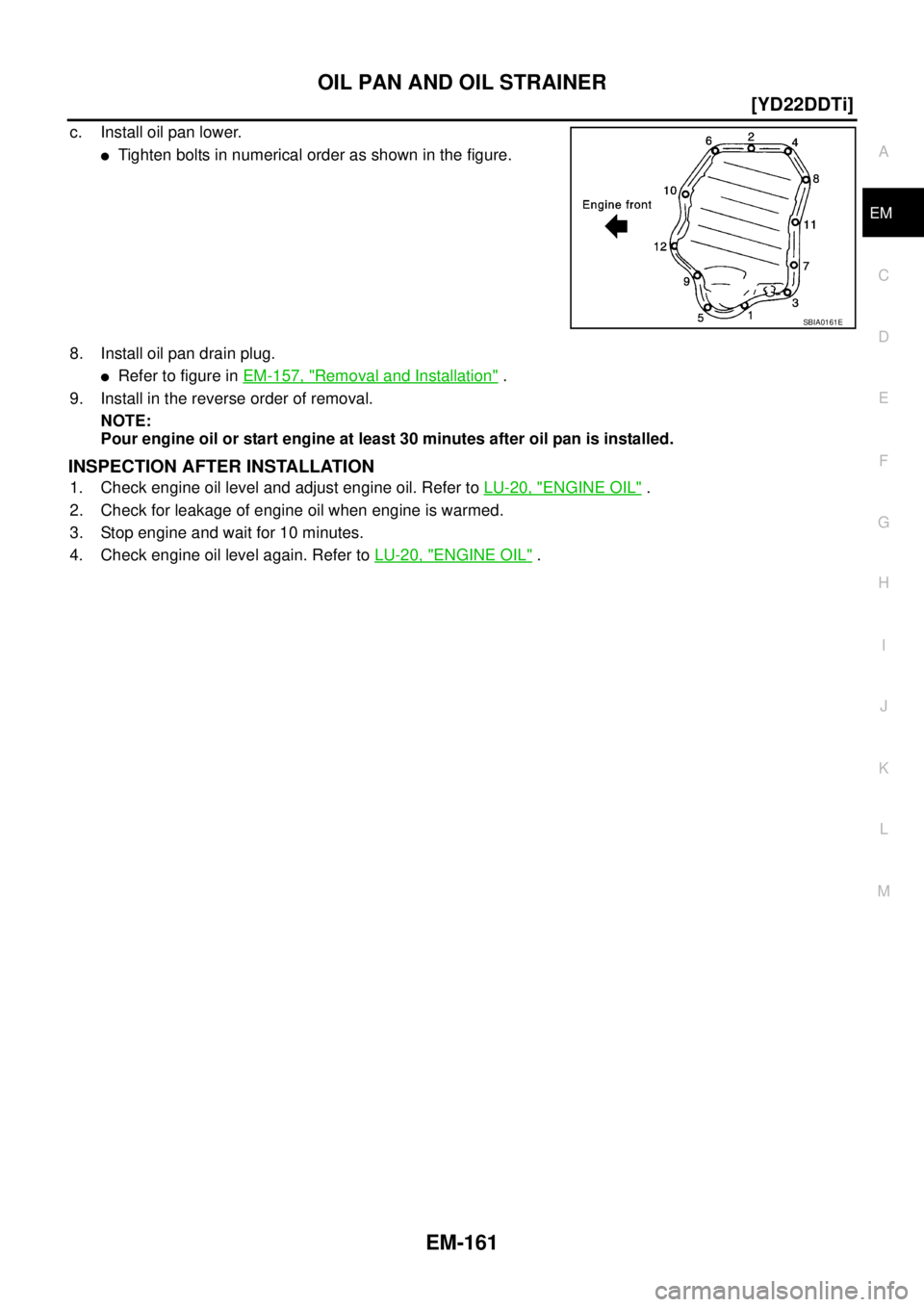
c. Install oil pan lower.
�Tighten bolts in numerical order as shown in the figure.
8. Install oil pan drain plug.
�Refer to figure in EM-157, "Removal and Installation" .
9. Install in the reverse order of removal.
NOTE:
Pour engine oil or start engine at least 30 minutes after oil pan is installed.
INSPECTION AFTER INSTALLATION
1. Check engine oil level and adjust engine oil. Refer to LU-20, "ENGINE OIL" .
2. Check for leakage of engine oil when engine is warmed.
3. Stop engine and wait for 10 minutes.
4. Check engine oil level again. Refer to LU-20, "
ENGINE OIL" .
SBIA0161E
Page 217 of 4555
![NISSAN X-TRAIL 2005 Service Repair Manual VACUUM PUMP
EM-163
[YD22DDTi]
C
D
E
F
G
H
I
J
K
L
MA
EM
VACUUM PUMPPFP:41920
Removal and InstallationEBS00LRM
INSPECTION BEFORE REMOVAL
1. Disconnect vacuum hose, and connect a vacuum gauge via 3-wa](/manual-img/5/57403/w960_57403-216.png "NISSAN X-TRAIL 2005 Service Repair Manual VACUUM PUMP
EM-163
[YD22DDTi]
C
D
E
F
G
H
I
J
K
L
MA
EM
VACUUM PUMPPFP:41920
Removal and InstallationEBS00LRM
INSPECTION BEFORE REMOVAL
1. Disconnect vacuum hose, and connect a vacuum gauge via 3-wa")
VACUUM PUMP
EM-163
[YD22DDTi]
C
D
E
F
G
H
I
J
K
L
MA
EM
VACUUM PUMPPFP:41920
Removal and InstallationEBS00LRM
INSPECTION BEFORE REMOVAL
1. Disconnect vacuum hose, and connect a vacuum gauge via 3-way connector.
�Disconnect point where vacuum from vacuum pump can be measured directly and install 3-way con-
nector.
2. Start engine and measure generated vacuum at idle speed.
�If out of standard, check for air suction in vacuum route, and measure again.
�If still outside of standard, replace vacuum pump.
REMOVAL
1. Drain engine coolant. Refer to CO-32, "Changing Engine Coolant" .
2. Remove air duct and air cleaner case (upper). Refer to EM-142, "
Removal and Installation" .
3. Remove charge air cooler. Refer to EM-144, "
Removal and Installation" .
4. Disconnect harness connector from fuel injector.
5. Remove injection tubes. Refer to EM-167, "
Removal and Installation" .
6. Remove rocker cover. Refer to EM-178, "
Removal and Installation" .
7. Remove spill tube. Refer to EM-167, "
Removal and Installation" .
8. Remove nozzle support from No. 2 cylinder and No. 2 fuel injector. Refer to EM-167, "
Removal and Instal-
lation" . (To fix the hexagonal portion of the camshaft.)
9. Remove air inlet pipes. Refer to EM-151, "
Removal and Installation" .
1.Vacuum pump and cylinder head rear cover
assembly2. O-ring 3. Cylinder head rear cover plate
4. Camshaft position sensor
PBIC3638E
Standard:
– 86.6 to – 101.3 kPa (– 866 to – 1,013 mbar, – 650 to – 760 mmHg, – 25.59 to – 29.92 inHg)
Page 219 of 4555
![NISSAN X-TRAIL 2005 Service Repair Manual VACUUM PUMP
EM-165
[YD22DDTi]
C
D
E
F
G
H
I
J
K
L
MA
EM
5. Install cylinder head rear cover plate.
�Apply a continuous bead of liquid gasket with the tube presser
(special service tool: WS39930000)](/manual-img/5/57403/w960_57403-218.png "NISSAN X-TRAIL 2005 Service Repair Manual VACUUM PUMP
EM-165
[YD22DDTi]
C
D
E
F
G
H
I
J
K
L
MA
EM
5. Install cylinder head rear cover plate.
�Apply a continuous bead of liquid gasket with the tube presser
(special service tool: WS39930000)")
VACUUM PUMP
EM-165
[YD22DDTi]
C
D
E
F
G
H
I
J
K
L
MA
EM
5. Install cylinder head rear cover plate.
�Apply a continuous bead of liquid gasket with the tube presser
(special service tool: WS39930000) to area shown in the fig-
ure.
Use Genuine Liquid Gasket or equivalent.
�Attaching should be done within 5 minutes after coating.
6. Install in reverse order of removal.
�When vacuum hose is connected, insert it securely by at least 15 mm (0.59 in).
CAUTION:
Do not start engine with vacuum circuit being open. If engine is started and vehicle is running while
vacuum pump is open (with vacuum hose disconnected), blow-by flow rate will increase and engine
may be damaged.
7. Before starting engine, bleed air from fuel piping. Refer to FL-18, "
Air Bleeding" .
INSPECTION AFTER INSTALLATION
Check generated vacuum satisfies the specification at idle speed. Refer to EM-163, "INSPECTION BEFORE
REMOVAL" .
Disassembly and AssemblyEBS00LRN
DISASSEMBLY
1. Remove drive chain from rear camshaft sprocket and vacuum pump sprocket.
2. Remove rear camshaft sprocket.
SBIA0169E
1. Rear camshaft sprocket 2. Drive chain 3. Chain guide
4. Cylinder head rear cover 5. Vacuum pump 6. O-ring
PBIC3639E
Page 220 of 4555
EM-166
[YD22DDTi]
VACUUM PUMP
3. Loosen chain guide mounting bolts. Then remove chain guide.
4. Remove vacuum pump.
CAUTION:
Do not disassemble vacuum pump.
ASSEMBLY
Follow procedure below to install each part onto cylinder head rear cover.
1. Install vacuum pump.
2. Temporarily fit chain guide.
�For performing procedure “6”, adjustment of chain guide.
3. Install rear camshaft sprocket.
4. Fit drive chain onto rear camshaft sprocket and vacuum pump
sprocket.
5. Install (insert) SST to rear camshaft sprocket from the rear via
cylinder head rear cover.
�SST installation allows positioning of rear camshaft sprocket.
6. Press chain guide lightly for positioning so that the clearance
between drive chain and chain guide reaches 0mm (0 in).
�Check tension of drive chain, and fully tighten two chain guide
bolts.
SBIA0171E
PBIC3847E
PBIC3848E
PBIC3898E
Page 224 of 4555
EM-170
[YD22DDTi]
INJECTION TUBE AND FUEL INJECTOR
CAUTION:
�Check gutter spring in nozzle oil seal on fuel injector for missing.
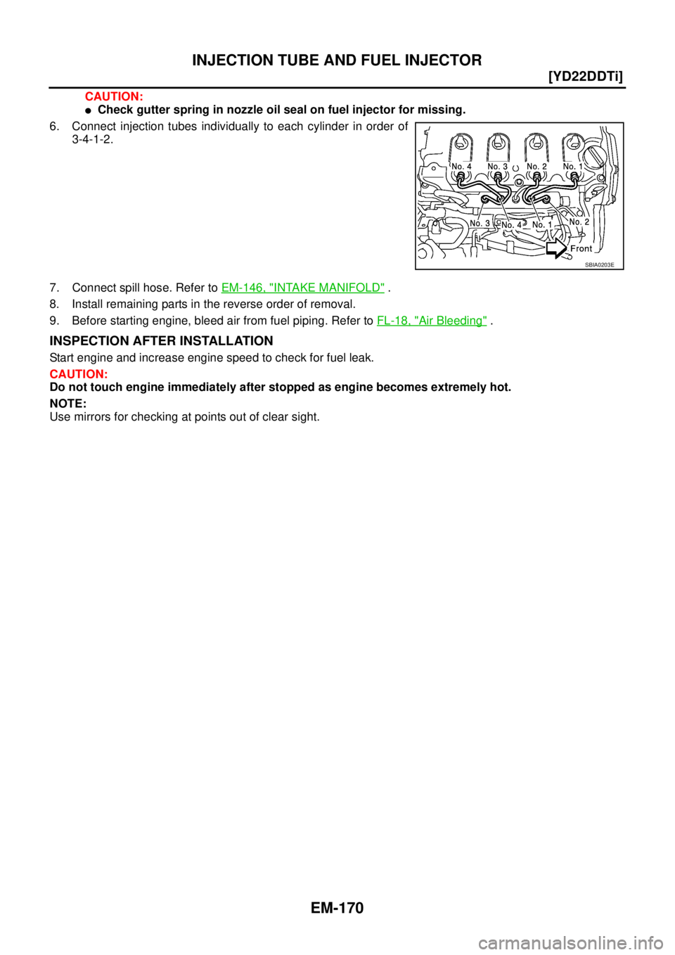
6. Connect injection tubes individually to each cylinder in order of
3-4-1-2.
7. Connect spill hose. Refer to EM-146, "
INTAKE MANIFOLD" .
8. Install remaining parts in the reverse order of removal.
9. Before starting engine, bleed air from fuel piping. Refer to FL-18, "
Air Bleeding" .
INSPECTION AFTER INSTALLATION
Start engine and increase engine speed to check for fuel leak.
CAUTION:
Do not touch engine immediately after stopped as engine becomes extremely hot.
NOTE:
Use mirrors for checking at points out of clear sight.
SBIA0203E
Page 229 of 4555
FUEL PUMP
EM-175
[YD22DDTi]
C
D
E
F
G
H
I
J
K
L
MA
EM
INSPECTION AFTER REMOVAL
Timing Chain
Check for cracks and excessive wear at roller links. Replace
timing chain if necessary.
INSTALLATION
1. Install new oil seal to spacer.
2. Install spacer to fuel pump.
3. Install coupling to fuel pump of spacer.
�Using the TORX wrench (special service tool), tighten the
sprocket nut to fix the coupling.
4. Install adjust shim.
�For shim adjustment, measure dimension “L” [Distance
between front surface of coupling and the fuel pump flange
(spacer)] at two opposing points near the coupling bolt center.
Use the average of these two measurements to select the
shim grade that marked on adjust shim.
�The shim adjustment is required only when the fuel pump is
replaced.
SEM984C
MBIA0045E
MBIA0013E
MBIA0077E
![NISSAN X-TRAIL 2005 Service Repair Manual EM-166
[YD22DDTi]
VACUUM PUMP
3. Loosen chain guide mounting bolts. Then remove chain guide.
4. Remove vacuum pump.
CAUTION:
Do not disassemble vacuum pump.
ASSEMBLY
Follow procedure below to instal](/manual-img/5/57403/w960_57403-219.png "NISSAN X-TRAIL 2005 Service Repair Manual EM-166
[YD22DDTi]
VACUUM PUMP
3. Loosen chain guide mounting bolts. Then remove chain guide.
4. Remove vacuum pump.
CAUTION:
Do not disassemble vacuum pump.
ASSEMBLY
Follow procedure below to instal")
![NISSAN X-TRAIL 2005 Service Repair Manual FUEL PUMP
EM-175
[YD22DDTi]
C
D
E
F
G
H
I
J
K
L
MA
EM
INSPECTION AFTER REMOVAL
Timing Chain
Check for cracks and excessive wear at roller links. Replace
timing chain if necessary.
INSTALLATION
1. In](/manual-img/5/57403/w960_57403-228.png "NISSAN X-TRAIL 2005 Service Repair Manual FUEL PUMP
EM-175
[YD22DDTi]
C
D
E
F
G
H
I
J
K
L
MA
EM
INSPECTION AFTER REMOVAL
Timing Chain
Check for cracks and excessive wear at roller links. Replace
timing chain if necessary.
INSTALLATION
1. In")