Page 233 of 4555
![NISSAN X-TRAIL 2005 Service Repair Manual ROCKER COVER
EM-179
[YD22DDTi]
C
D
E
F
G
H
I
J
K
L
MA
EM
�Loosen holding bolts in reverse order of that shown in the fig-
ure and remove.
6. Remove rocker cover gasket.
INSTALLATION
1. Apply 3.0 mm](/manual-img/5/57403/w960_57403-232.png "NISSAN X-TRAIL 2005 Service Repair Manual ROCKER COVER
EM-179
[YD22DDTi]
C
D
E
F
G
H
I
J
K
L
MA
EM
�Loosen holding bolts in reverse order of that shown in the fig-
ure and remove.
6. Remove rocker cover gasket.
INSTALLATION
1. Apply 3.0 mm")
ROCKER COVER
EM-179
[YD22DDTi]
C
D
E
F
G
H
I
J
K
L
MA
EM
�Loosen holding bolts in reverse order of that shown in the fig-
ure and remove.
6. Remove rocker cover gasket.
INSTALLATION
1. Apply 3.0 mm (0.118 in) dia. on locations shown in the figure.
�Use Genuine Liquid Gasket or equivalent.
2. Install rocker cover gasket to rocker cover.
3. Tighten holding bolts in numerical order shown in the figure.
Re-tighten to the same torque in the same order as above.
4. Install nozzle oil seal.
�Insert it straight until flange fully contacts rocker cover.
5. Install remaining parts in the reverse order of removal.
6. Before starting engine, bleed air from fuel piping. Refer to FL-18, "
Air Bleeding" .
INSPECTION AFTER INSTALLATION
Start engine and increase engine speed to check for fuel leak.
CAUTION:
Do not touch the engine immediately after stopped as engine becomes extremely hot.
NOTE:
Use mirrors for checking at points out of clear sight.
SBIA0175E
JEM248G
: 7.8 N·m (0.8 kg-m, 69 in-lb)
SBIA0175E
Page 235 of 4555
![NISSAN X-TRAIL 2005 Service Repair Manual CAMSHAFT
EM-181
[YD22DDTi]
C
D
E
F
G
H
I
J
K
L
MA
EM
�Loosen the camshaft sprocket mounting bolt by fixing the hex-
agonal portion of camshaft.
10.11. Remove camshaft as follows:
a. Loosen and remov](/manual-img/5/57403/w960_57403-234.png "NISSAN X-TRAIL 2005 Service Repair Manual CAMSHAFT
EM-181
[YD22DDTi]
C
D
E
F
G
H
I
J
K
L
MA
EM
�Loosen the camshaft sprocket mounting bolt by fixing the hex-
agonal portion of camshaft.
10.11. Remove camshaft as follows:
a. Loosen and remov")
CAMSHAFT
EM-181
[YD22DDTi]
C
D
E
F
G
H
I
J
K
L
MA
EM
�Loosen the camshaft sprocket mounting bolt by fixing the hex-
agonal portion of camshaft.
10.11. Remove camshaft as follows:
a. Loosen and remove the camshaft sprocket bolts in reverse order
shown in the figure.
b. Place distinguishing marks on the right and left sides with paint.
12. Remove adjusting shim and valve lifter.
�Remove by taking notice of the installation position, and place outside engine in order to prevent confu-
sion.
INSPECTION AFTER REMOVAL
Visual Check of Camshaft
�Check the camshaft for one sided wear or scratches.
�Replace the camshaft if there are abnormalities.
Camshaft Runout
�Prepare V-block on a flat surface and secure camshaft journals
No. 2 and No. 5.
�Set the dial indicator vertically on journal No. 3.
�Rotate camshaft in one direction by hand, then read needle
movement on dial indicator (total indicator reading).
�If it exceeds the limit, replace camshaft.
Camshaft Cam Height
�Measure the height of camshaft cam using the micrometer.
�If out of the standard, replace camshaft.
JEM159G
JEM160G
Limit : 0.02 mm (0.0008 in)
PBIC2499E
Standard:
Intake : 39.505 - 39.695 mm (1.5553 - 1.5628 in)
Exhaust : 39.905 - 40.095 mm (1.5711 - 1.5785 in)
SEM549A
Page 237 of 4555
CAMSHAFT
EM-183
[YD22DDTi]
C
D
E
F
G
H
I
J
K
L
MA
EM
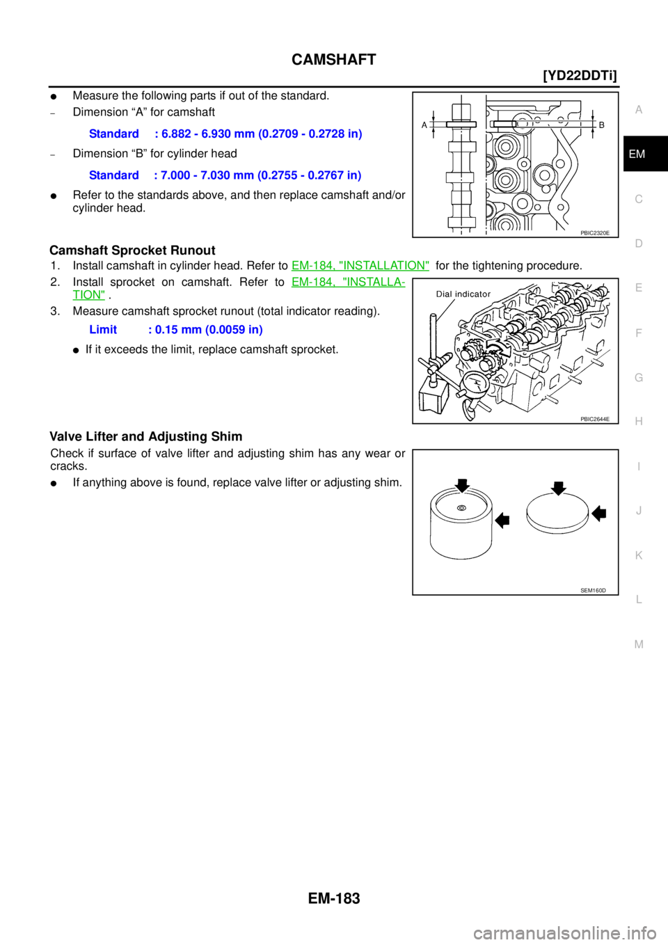
�Measure the following parts if out of the standard.
–Dimension “A” for camshaft
–Dimension “B” for cylinder head
�Refer to the standards above, and then replace camshaft and/or
cylinder head.
Camshaft Sprocket Runout
1. Install camshaft in cylinder head. Refer to EM-184, "INSTALLATION" for the tightening procedure.
2. Install sprocket on camshaft. Refer to EM-184, "
INSTALLA-
TION" .
3. Measure camshaft sprocket runout (total indicator reading).
�If it exceeds the limit, replace camshaft sprocket.
Valve Lifter and Adjusting Shim
Check if surface of valve lifter and adjusting shim has any wear or
cracks.
�If anything above is found, replace valve lifter or adjusting shim. Standard : 6.882 - 6.930 mm (0.2709 - 0.2728 in)
Standard : 7.000 - 7.030 mm (0.2755 - 0.2767 in)
PBIC2320E
Limit : 0.15 mm (0.0059 in)
PBIC2644E
SEM160D
Page 239 of 4555
![NISSAN X-TRAIL 2005 Service Repair Manual CAMSHAFT
EM-185
[YD22DDTi]
C
D
E
F
G
H
I
J
K
L
MA
EM
�Install so that knock pins are positioned in the directions
shown in the figure.
NOTE:
Though camshaft does not stop at the location as shown in](/manual-img/5/57403/w960_57403-238.png "NISSAN X-TRAIL 2005 Service Repair Manual CAMSHAFT
EM-185
[YD22DDTi]
C
D
E
F
G
H
I
J
K
L
MA
EM
�Install so that knock pins are positioned in the directions
shown in the figure.
NOTE:
Though camshaft does not stop at the location as shown in")
CAMSHAFT
EM-185
[YD22DDTi]
C
D
E
F
G
H
I
J
K
L
MA
EM
�Install so that knock pins are positioned in the directions
shown in the figure.
NOTE:
Though camshaft does not stop at the location as shown in
the figure, for the placement of cam nose, it is generally
accepted that camshaft is placed at the same direction as
shown in the figure.
3. Install camshaft brackets.
�Completely remove any foreign material on back surfaces of camshaft brackets and top surface of cyl-
inder head.
�Install correctly, identifying brackets by the journal No. and
front mark on top surface.
4. Tighten bolts in the order shown in the figure according to the
following procedure:
a. Tighten all bolts.
�Make sure camshaft thrusting parts (on rear side) securely fit
in their mating parts on the cylinder head.
b. Tighten all bolts.
c. Tighten all bolts.
5. Install camshaft sprockets.
�Camshaft sprockets are commonly used for right side and left side.
�Align camshaft sprocket and knock pin on camshaft, and install.
�Holding the hexagonal part of camshaft with a wrench, tighten bolt securing camshaft sprocket.
6. Before installing spill tube after installing secondary timing chain, check and adjust valve clearance. Refer
to EM-185, "
Valve Clearance" .
7. Hereafter, install in the reverse order of removal.
8. Before starting engine, bleed air from fuel piping. Refer to FL-18, "
Air Bleeding" .
Va l v e C l e a r a n c eEBS00LRS
INSPECTION
�When the camshaft or parts in connection with valves are removed or replaced, and a malfunction has
occurred (poor starting, idling, or other malfunction) due to the misadjustment of the valve clearance,
inspect as follows.
�Inspect and adjust when the engine is cool (at normal temperature).
PBIC2026E
JEM175G
: 2 N·m (0.2 kg-m, 1 ft-lb)
: 6 N·m (0.6 kg-m, 4 ft-lb)
: 12.5 N·m (1.3 kg-m, 9 ft-lb)
JEM160G
Page 243 of 4555
![NISSAN X-TRAIL 2005 Service Repair Manual CAMSHAFT
EM-189
[YD22DDTi]
C
D
E
F
G
H
I
J
K
L
MA
EM
9. Select the new adjusting shim from the following methods.
�New adjusting shims have the thickness stamped on the rear
side.
�Shims are availab](/manual-img/5/57403/w960_57403-242.png "NISSAN X-TRAIL 2005 Service Repair Manual CAMSHAFT
EM-189
[YD22DDTi]
C
D
E
F
G
H
I
J
K
L
MA
EM
9. Select the new adjusting shim from the following methods.
�New adjusting shims have the thickness stamped on the rear
side.
�Shims are availab")
CAMSHAFT
EM-189
[YD22DDTi]
C
D
E
F
G
H
I
J
K
L
MA
EM
9. Select the new adjusting shim from the following methods.
�New adjusting shims have the thickness stamped on the rear
side.
�Shims are available in 33 size from 2.10 mm (0.0827 in) to
2.74 mm (0.1079 in), in steps of 0.02 mm (0.0008 in).
10. Fit the selected adjusting shim to valve lifter.
CAUTION:
Place the stamped side of adjusting shim to valve lifter.
11. Compress valve spring using the camshaft pliers (special service tool: KV10115110) and remove the lifter
stopper (special service tool).
12. Rotate crankshaft 2 to 3 turns by hand.
13. Confirm that the valve clearance is within the specification. Refer to EM-185, "
INSPECTION" .
14. Install remaining parts in the reverse order of removal. Refer to EM-184, "
INSTALLATION" .
15. Warm up the engine, and check for unusual noise and vibration.Calculation method of the adjusting shim thickness:
R = Thickness of removed shim
N = Thickness of new shim
M = Measured valve clearance
Intake
N = R + [M - 0.28 mm (0.0010 in)]
Exhaust
N = R + [M - 0.30 mm (0.0118 in)]
Stamped mark Shim thickness mm (in)
2.10
2.12
·
·
·
2.74 2.10 (0.0827)
2.12 (0.0835)
·
·
·
2.74 (0.1079)
JEM184G
PBIC2325E
Page 244 of 4555
![NISSAN X-TRAIL 2005 Service Repair Manual EM-190
[YD22DDTi]
OIL SEAL
OIL SEALPFP:12279
Removal and Installation of Valve Oil SealEBS01FBM
REMOVAL
1. Remove camshafts. Refer toEM-180, "Removal and Installation" .
2. Remove adjusting shims an](/manual-img/5/57403/w960_57403-243.png "NISSAN X-TRAIL 2005 Service Repair Manual EM-190
[YD22DDTi]
OIL SEAL
OIL SEALPFP:12279
Removal and Installation of Valve Oil SealEBS01FBM
REMOVAL
1. Remove camshafts. Refer toEM-180, \"Removal and Installation\" .
2. Remove adjusting shims an")
EM-190
[YD22DDTi]
OIL SEAL
OIL SEALPFP:12279
Removal and Installation of Valve Oil SealEBS01FBM
REMOVAL
1. Remove camshafts. Refer toEM-180, "Removal and Installation" .
2. Remove adjusting shims and valve lifters. Refer to EM-180, "
Removal and Installation" .
�Check the installation positions, and keep them to avoid being confused.
3. Rotate crankshaft, and set piston whose valve oil seal is to be removed to TDC. This will prevent valve
from dropping into cylinder.
4. Remove valve collet.
�Compress the valve spring with valve spring compressor,
attachment and adapter (special service tool). Remove valve
collet with a magnet hand.
CAUTION:
When working, be careful not to damage valve lifter holes.
5. Remove valve spring retainer and valve spring.
6. Remove valve oil seal with the valve oil seal puller (special ser-
vice tool).
INSTALLATION
1. Apply new engine oil to valve oil seal joint surface and seal lip.
2. Using the valve oil seal drift (special service tool), install valve oil
seals referring to the dimension shown in the figure.
3. Install in the reverse order of removal.
PBIC2388E
JEM153G
JEM165G
Page 249 of 4555
SECONDARY TIMING CHAIN
EM-195
[YD22DDTi]
C
D
E
F
G
H
I
J
K
L
MA
EM
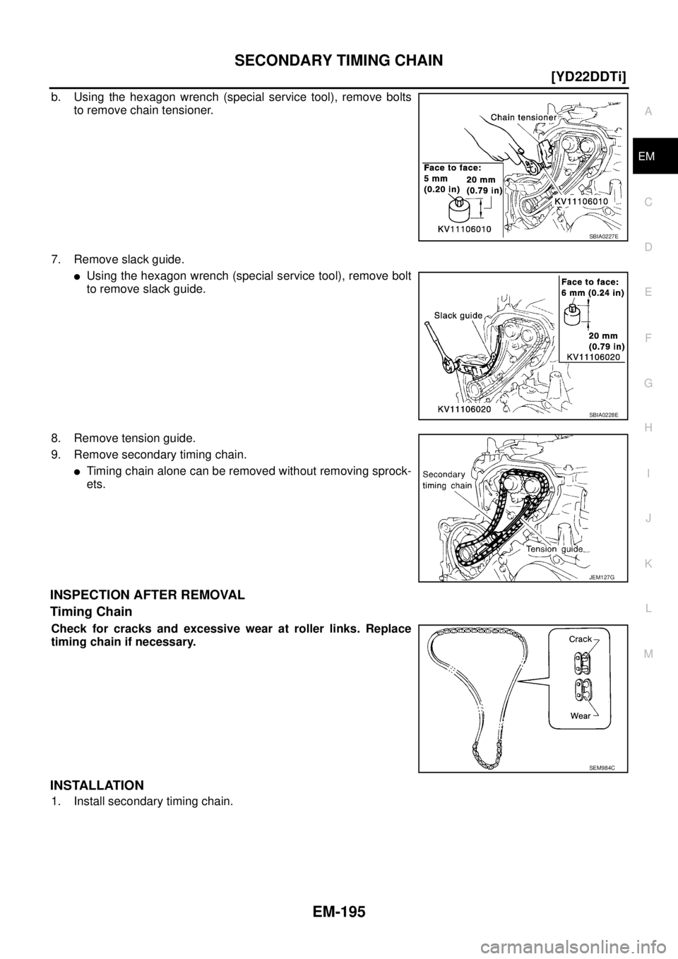
b. Using the hexagon wrench (special service tool), remove bolts
to remove chain tensioner.
7. Remove slack guide.
�Using the hexagon wrench (special service tool), remove bolt
to remove slack guide.
8. Remove tension guide.
9. Remove secondary timing chain.
�Timing chain alone can be removed without removing sprock-
ets.
INSPECTION AFTER REMOVAL
Timing Chain
Check for cracks and excessive wear at roller links. Replace
timing chain if necessary.
INSTALLATION
1. Install secondary timing chain.
SBIA0227E
SBIA0228E
JEM127G
SEM984C
Page 257 of 4555
PRIMARY TIMING CHAIN
EM-203
[YD22DDTi]
C
D
E
F
G
H
I
J
K
L
MA
EM
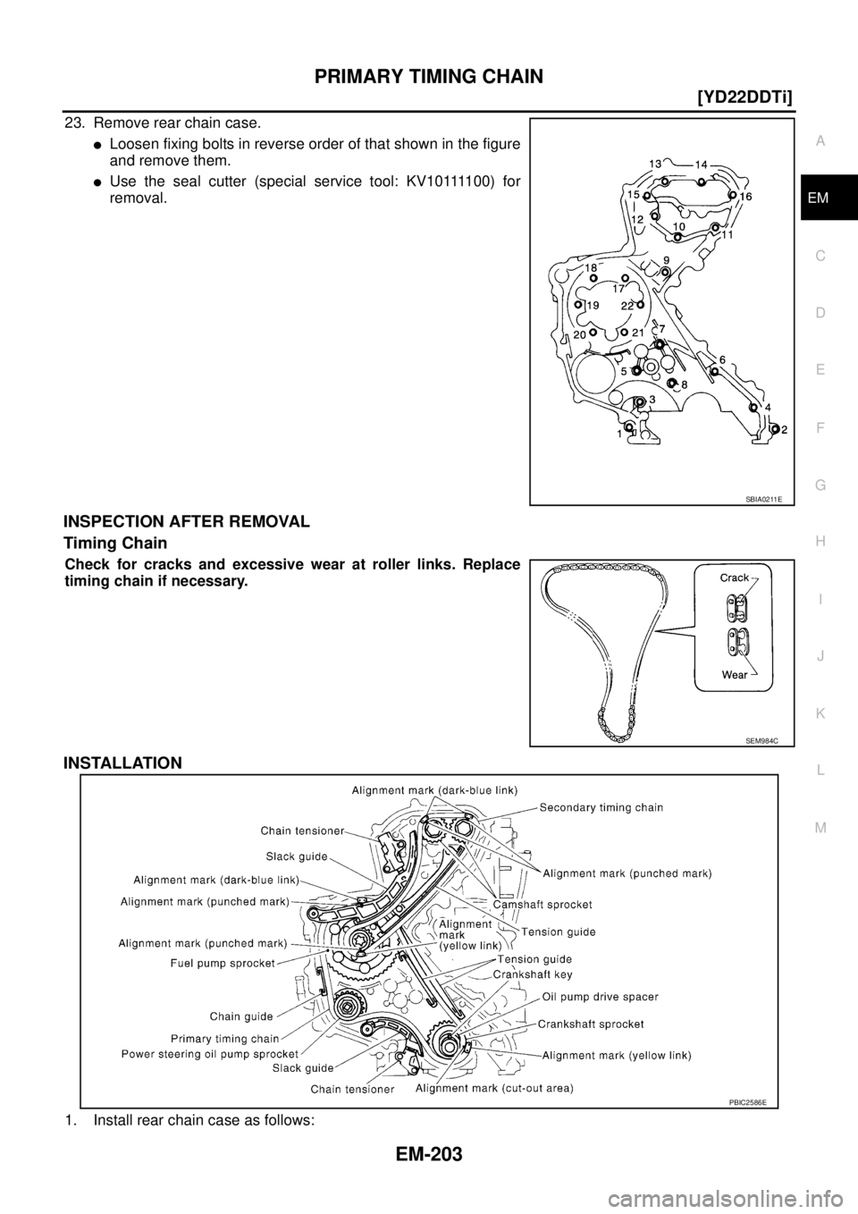
23. Remove rear chain case.
�Loosen fixing bolts in reverse order of that shown in the figure
and remove them.
�U s e t h e s e a l c u t t e r ( s p e c i a l s e r v i c e t o o l : K V 1 0 1111 0 0 ) f o r
removal.
INSPECTION AFTER REMOVAL
Timing Chain
Check for cracks and excessive wear at roller links. Replace
timing chain if necessary.
INSTALLATION
1. Install rear chain case as follows:
SBIA0211E
SEM984C
PBIC2586E