Page 2287 of 4555

OVERALL SYSTEM
AT-23
D
E
F
G
H
I
J
K
L
MA
B
AT
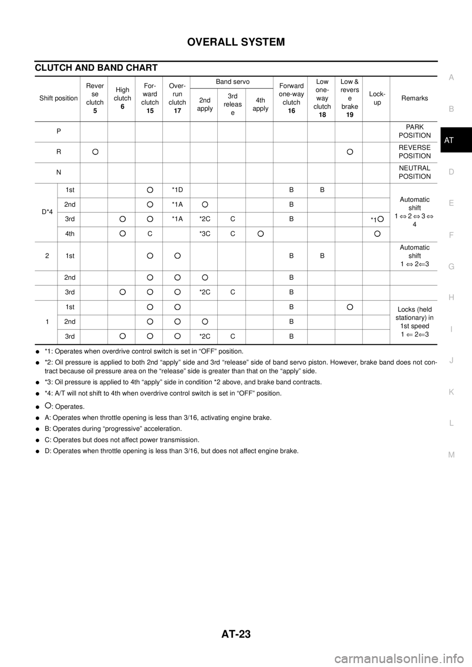
CLUTCH AND BAND CHART
�*1: Operates when overdrive control switch is set in “OFF” position.
�*2: Oil pressure is applied to both 2nd “apply” side and 3rd “release” side of band servo piston. However, brake band does not con-
tract because oil pressure area on the “release” side is greater than that on the “apply” side.
�*3: Oil pressure is applied to 4th “apply” side in condition *2 above, and brake band contracts.
�*4: A/T will not shift to 4th when overdrive control switch is set in “OFF” position.
�: Operates.
�A: Operates when throttle opening is less than 3/16, activating engine brake.
�B: Operates during “progressive” acceleration.
�C: Operates but does not affect power transmission.
�D: Operates when throttle opening is less than 3/16, but does not affect engine brake. Shift positionRever
se
clutch
5High
clutch
6For-
ward
clutch
15Over-
run
clutch
17Band servo
Forward
one-way
clutch
16Low
one-
way
clutch
18Low &
revers
e
brake
19Lock-
upRemarks
2nd
apply3rd
releas
e4th
apply
PPA R K
POSITION
RREVERSE
POSITION
NNEUTRAL
POSITION
D*41st *1D B B
Automatic
shift
1 ⇔ 2 ⇔ 3 ⇔
4 2nd *1A B
3rd *1A *2C C B
*1
4th C *3C C
21stBBAutomatic
shift
1 ⇔ 2⇐3
2ndB
3rd *2C C B
11stB
Locks (held
stationary) in
1st speed
1 ⇐ 2⇐3 2ndB
3rd *2C C B
Page 2288 of 4555
AT-24
OVERALL SYSTEM
POWER TRANSMISSION
“N” and “P” Positions
�“N” position
Power from the input shaft is not transmitted to the output shaft because the clutches do not operate.
�“P” position
Similar to the “N” position, the clutches do not operate. The parking pawl engages with the parking gear to
mechanically hold the output shaft so that the power train is locked.
SAT991I
Page 2293 of 4555
OVERALL SYSTEM
AT-29
D
E
F
G
H
I
J
K
L
MA
B
AT
“D4 ” (O/D) Position
�High clutch
�Brake band
�Forward clutch (Does not affect power
transmission)Input power is transmitted to front carrier through high clutch.
This front carrier turns around the sun gear which is fixed by brake band and makes
front internal gear (output) turn faster.
Engine brakeAt D
4 position, there is no one-way clutch in the power transmission line and engine
brake can be obtained when decelerating.
SAT380J
Page 2294 of 4555
AT-30
OVERALL SYSTEM
“R” Position
�Reverse clutch
�Low & reverse brakeFront planetary carrier is stationary because of the operation of low and reverse brake.
Input power is transmitted to front sun gear through reverse clutch, which drives front
internal gear in the opposite direction.
Engine brakeAs there is no one-way clutch in the power transmission line, engine brake can be
obtained when decelerating.
SAT381J
Page 2296 of 4555

AT-32
OVERALL SYSTEM
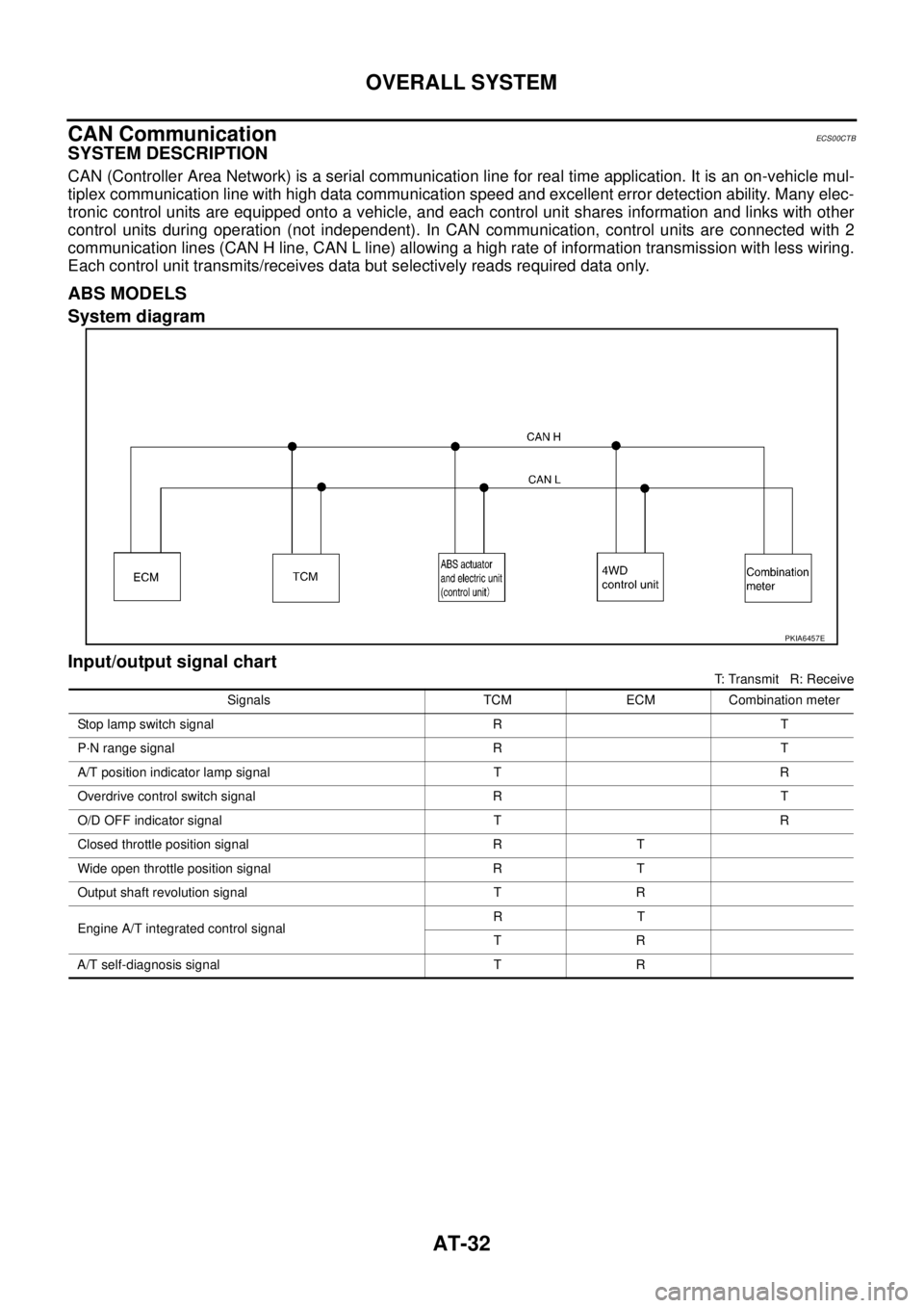
CAN CommunicationECS00CTB
SYSTEM DESCRIPTION
CAN (Controller Area Network) is a serial communication line for real time application. It is an on-vehicle mul-
tiplex communication line with high data communication speed and excellent error detection ability. Many elec-
tronic control units are equipped onto a vehicle, and each control unit shares information and links with other
control units during operation (not independent). In CAN communication, control units are connected with 2
communication lines (CAN H line, CAN L line) allowing a high rate of information transmission with less wiring.
Each control unit transmits/receives data but selectively reads required data only.
ABS MODELS
System diagram
Input/output signal chart
T: Transmit R: Receive
PKIA6457E
Signals TCM ECM Combination meter
Stop lamp switch signal R T
P·N range signal R T
A/T position indicator lamp signal T R
Overdrive control switch signal R T
O/D OFF indicator signal T R
Closed throttle position signal R T
Wide open throttle position signal R T
Output shaft revolution signal T R
Engine A/T integrated control signalRT
TR
A/T self-diagnosis signal T R
Page 2300 of 4555

AT-36
OVERALL SYSTEM
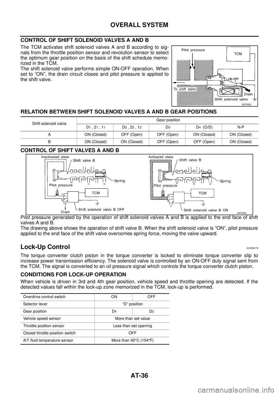
CONTROL OF SHIFT SOLENOID VALVES A AND B
The TCM activates shift solenoid valves A and B according to sig-
nals from the throttle position sensor and revolution sensor to select
the optimum gear position on the basis of the shift schedule memo-
rized in the TCM.
The shift solenoid valve performs simple ON-OFF operation. When
set to “ON”, the drain circuit closes and pilot pressure is applied to
the shift valve.
RELATION BETWEEN SHIFT SOLENOID VALVES A AND B GEAR POSITIONS
CONTROL OF SHIFT VALVES A AND B
Pilot pressure generated by the operation of shift solenoid valves A and B is applied to the end face of shift
valves A and B.
The drawing above shows the operation of shift valve B. When the shift solenoid valve is “ON”, pilot pressure
applied to the end face of the shift valve overcomes spring force, moving the valve upward.
Lock-Up ControlECS00CTE
The torque converter clutch piston in the torque converter is locked to eliminate torque converter slip to
increase power transmission efficiency. The solenoid valve is controlled by an ON-OFF duty signal sent from
the TCM. The signal is converted to an oil pressure signal which controls the torque converter clutch piston.
CONDITIONS FOR LOCK-UP OPERATION
When vehicle is driven in 3rd and 4th gear position, vehicle speed and throttle opening are detected. If the
detected values fall within the lock-up zone memorized in the TCM, lock-up is performed.
SAT008J
Shift solenoid valveGear position
D1 , 21 , 11D2 , 22 , 12D3D4 (O/D) N-P
A ON (Closed) OFF (Open) OFF (Open) ON (Closed) ON (Closed)
B ON (Closed) ON (Closed) OFF (Open) OFF (Open) ON (Closed)
SAT009J
Overdrive control switch ON OFF
Selector lever “D” position
Gear position D
4D3
Vehicle speed sensor More than set value
Throttle position sensor Less than set opening
Closed throttle position switch OFF
A/T fluid temperature sensor More than 40°C (104°F)
Page 2361 of 4555
![NISSAN X-TRAIL 2005 Service Repair Manual DTC U1000 CAN COMMUNICATION LINE
AT-97
[EURO-OBD]
D
E
F
G
H
I
J
K
L
MA
B
AT
DTC U1000 CAN COMMUNICATION LINEPFP:31940
DescriptionECS008CZ
CAN (Controller Area Network) is a serial communication line NISSAN X-TRAIL 2005 Service Repair Manual DTC U1000 CAN COMMUNICATION LINE
AT-97
[EURO-OBD]
D
E
F
G
H
I
J
K
L
MA
B
AT
DTC U1000 CAN COMMUNICATION LINEPFP:31940
DescriptionECS008CZ
CAN (Controller Area Network) is a serial communication line](/manual-img/5/57403/w960_57403-2360.png)
DTC U1000 CAN COMMUNICATION LINE
AT-97
[EURO-OBD]
D
E
F
G
H
I
J
K
L
MA
B
AT
DTC U1000 CAN COMMUNICATION LINEPFP:31940
DescriptionECS008CZ
CAN (Controller Area Network) is a serial communication line for real time application. It is an on-vehicle mul-
tiplex communication line with high data communication speed and excellent error detection ability. Many elec-
tronic control units are equipped onto a vehicle, and each control unit shares information and links with other
control units during operation (not independent). In CAN communication, control units are connected with 2
communication lines (CAN H line, CAN L line) allowing a high rate of information transmission with less wiring.
Each control unit transmits/receives data but selectively reads required data only.
On Board Diagnosis LogicECS008D0
Possible CauseECS00CUO
Harness or connectors
(CAN communication line is open or shorted.)
DTC Confirmation ProcedureECS008D1
NOTE:
If “DTC Confirmation Procedure” has been previously conducted, always turn ignition switch OFF and
wait at least 10 seconds before conducting the next test.
After the repair, perform the following procedure to confirm the malfunction is eliminated.
WITH CONSULT-II
1. Turn ignition switch ON. (Do not start engine.)
2. Select “DATA MONITOR” mode for “A/T” with CONSULT-II.
3. Wait at least 6 seconds or start engine and wait for at least 6
seconds.
4. If DTC is detected, go to AT- 9 9 , "
Diagnostic Procedure" .
WITH GST
Follow the procedure “WITH CONSULT-II”
WITHOUT CONSULT-II
1. Turn ignition switch ON. (Do not start engine.)
2. Wait at least 6 seconds or start engine and wait at least 6 seconds.
3. Perform self-diagnosis.
Refer to AT- 5 2 , "
Diagnostic Procedure Without CONSULT-II" .
4. If DTC is detected, go to AT- 9 9 , "
Diagnostic Procedure" .
Diagnostic trouble code Malfunction is detected when... Check items (Possible cause)
:CAN COMM CIRCUIT
When a malfunction is detected in CAN
communication line.
�Harness or connectors
(CAN communication line is open or
shorted.) :11th judgement flicker
SAT014K
SCIA4673E
Page 2593 of 4555
![NISSAN X-TRAIL 2005 Service Repair Manual CAN COMMUNICATION LINE
AT-329
[ALL]
D
E
F
G
H
I
J
K
L
MA
B
AT
[ALL]CAN COMMUNICATION LINEPFP:31940
DescriptionECS004UJ
CAN (Control Area Network) is a serial communication line for real time applica NISSAN X-TRAIL 2005 Service Repair Manual CAN COMMUNICATION LINE
AT-329
[ALL]
D
E
F
G
H
I
J
K
L
MA
B
AT
[ALL]CAN COMMUNICATION LINEPFP:31940
DescriptionECS004UJ
CAN (Control Area Network) is a serial communication line for real time applica](/manual-img/5/57403/w960_57403-2592.png)
CAN COMMUNICATION LINE
AT-329
[ALL]
D
E
F
G
H
I
J
K
L
MA
B
AT
[ALL]CAN COMMUNICATION LINEPFP:31940
DescriptionECS004UJ
CAN (Control Area Network) is a serial communication line for real time application. It is an on-vehicle multi-
plex communication line with high data communication speed and excellent error detection ability. Many elec-
tronic control units are equipped onto a vehicle, and each control unit shares information and links with other
control units during operation (not independent). In CAN communication, control units are connected with 2
communication lines (CAN H line, CAN L line) allowing a high rate of information transmission with less wiring.
Each control unit transmits/receives data but selectively reads required data only.
On Board Diagnosis LogicECS004UK
Possible CauseECS00CT9
Harness or connector
(CAN communication line is open or shorted.)
DTC Confirmation ProcedureECS004UL
NOTE:
If “DTC Confirmation Procedure” has been previously conducted, always turn ignition switch OFF and
wait at least 10 seconds before conducting the next test.
After the repair, perform the following procedure to confirm the malfunction is eliminated.
WITH CONSULT-II
1. Turn ignition switch ON. (Do not start engine.)
2. Select “DATA MONITOR” mode for “A/T” with CONSULT-II.
3. Wait at least 6 seconds or start engine and wait for at least 6
seconds.
4. If DTC is detected, go to AT- 3 3 1 , "
Diagnostic Procedure" .
WITHOUT CONSULT-II
1. Turn ignition switch ON. (Do not start engine.)
2. Wait at least 6 seconds or start engine and wait at least 6 sec-
onds.
3. Perform self-diagnosis.
Refer to AT- 5 2 , "
Diagnostic Procedure Without CONSULT-II" .
4. If DTC is detected, go to AT- 3 3 1 , "
Diagnostic Procedure" .
Diagnostic trouble code Malfunction is detected when... Check items (Possible cause)
: CAN COMM CIRCUIT
When a malfunction is detected in CAN
communication line.
�Harness or connectors
(CAN communication line is open or
shorted.)
: 11th judgement flicker
SAT014K
SCIA4673E