Page 2117 of 4555
FUEL TANK
FL-11
[QR]
C
D
E
F
G
H
I
J
K
L
MA
FL
FUEL TANKPFP:17202
Removal and InstallationEBS00KOW
REMOVAL
WARNING:
Be sure to read “General Precautions” when working on the fuel system. Refer to FL-3, "
General Pre-
cautions" .
1. Perform the steps 1 to 7 of “REMOVAL” in “ FUEL LEVEL SENSOR UNIT, FUEL FILTER AND FUEL
PUMP ASSEMBLY”. Refer to FL-4, "
REMOVAL" .
2. Drain fuel more from fuel tank if necessary.
CAUTION:
Because fuel tank forwardly inclines and becomes unstable when installing/removing, fuel should
be drained if found the remaining quantity.
3. Remove exhaust center tube and insulator. Refer to EX-2, "
EXHAUST SYSTEM" .
4. Remove propeller shaft. (4WD models) Refer to PR-3, "
REAR PROPELLER SHAFT" .
PBIC0246E
1. Fuel filler cap 2. Grommet 3. Fuel filler tube
4. Vent hose 5. Vent tube 6. Fuel tank
7. Fuel filler hose 8. Fuel tank band 9. Fuel tank protector
Page 2118 of 4555
![NISSAN X-TRAIL 2005 Service Repair Manual FL-12
[QR]
FUEL TANK
5. Using a transmission jack, support the bottom of final drive
assembly (4WD models) or rear suspension member (2WD
models).
6. Remove mounting nuts on rear suspension member, NISSAN X-TRAIL 2005 Service Repair Manual FL-12
[QR]
FUEL TANK
5. Using a transmission jack, support the bottom of final drive
assembly (4WD models) or rear suspension member (2WD
models).
6. Remove mounting nuts on rear suspension member,](/manual-img/5/57403/w960_57403-2117.png)
FL-12
[QR]
FUEL TANK
5. Using a transmission jack, support the bottom of final drive
assembly (4WD models) or rear suspension member (2WD
models).
6. Remove mounting nuts on rear suspension member, and lower
the transmission jack carefully until just before rear suspension
member is removed from stud bolts on the vehicle. Refer to
RSU-5, "
REAR SUSPENSION ASSEMBLY" .
7. Disconnect fuel filler hose, EVAP hose and vent hose at fuel
tank side.
�For disconnection procedure of quick connector on EVAP
hose, refer to FL-4, "
FUEL LEVEL SENSOR UNIT, FUEL FIL-
TER AND FUEL PUMP ASSEMBLY" .
8. Remove fuel tank protector.
9. Remove fuel tank band mounting bolts while supporting fuel
tank.
CAUTION:
Sustain the bottom of fuel tank by using plate or anything
same.
10. Remove fuel tank.
�After lifting down the front portion of fuel tank, remove fuel
tank by pulling it from the upper front of final drive assembly,
so that fuel tank can move forwardly.
CAUTION:
Pay attention not to fall fuel tank because it forwardly
inclines and becomes unstable.
NOTE:
It is desirable that more than two technicians work together.
INSTALLATION
Note the following, and install in the reverse order of removal.
�Surely clamp fuel hoses and insert hose to the length below.
�Be sure hose clamp is not placed on swelled area of fuel tube.
�Tighten fuel hose clamp so that the remaining length of screw thread becomes to the following.
�Fit fuel tank band pin to the vehicle side securely.
�Before fixing fuel tank, temporarily install fuel filler tube.
KBIA0285E
KBIA0286E
KBIA0290E
Fuel filler hose : 35mm (1.38 in)
The other hoses : 25mm (0.98 in)
Fuel tank side : 5 - 9 mm (0.20 - 0.35 in)
Fuel filler tube side : 7 - 11 mm (0.28 - 0.43 in)
Page 2129 of 4555
FUEL TANK
FL-23
[YD22DDTi]
C
D
E
F
G
H
I
J
K
L
MA
FL
FUEL TANKPFP:17202
Removal and InstallationEBS00BL3
REMOVAL
WARNING:
Be sure to read “General Precautions” when working on fuel system. Refer to FL-16, "
General Precau-
tions" .
1. Perform the procedure from 1 to 7 in “removal” of FL-19, "
FUEL LEVEL SENSOR UNIT" .
2. Drain fuel more from fuel tank if necessary.
CAUTION:
Because fuel tank forwardly inclines and becomes unstable when installing/removing, fuel should
be drained if found the remaining quantity.
3. Remove exhaust center tube and insulator. Refer to EX-2, "
EXHAUST SYSTEM" .
4. Remove propeller shaft. (4WD models) Refer to PR-3, "
REAR PROPELLER SHAFT" .
1. Fuel filler cap 2. Grommet 3. Fuel filler tube
4. Vent hose 5. Vent tube 6. EVAP hose
7. Fuel filler hose 8. Fuel transport pump 9. Fuel hose
10. Fuel tube 11. Fuel tank protector 12. Fuel tank band
13. Fuel tank
PBIC2033E
Page 2130 of 4555
![NISSAN X-TRAIL 2005 Service Repair Manual FL-24
[YD22DDTi]
FUEL TANK
5. Using a transmission jack, support the bottom of final drive
assembly (4WD models) or rear suspension member (2WD
models).
6. Remove the mounting nuts on the rear suspe NISSAN X-TRAIL 2005 Service Repair Manual FL-24
[YD22DDTi]
FUEL TANK
5. Using a transmission jack, support the bottom of final drive
assembly (4WD models) or rear suspension member (2WD
models).
6. Remove the mounting nuts on the rear suspe](/manual-img/5/57403/w960_57403-2129.png)
FL-24
[YD22DDTi]
FUEL TANK
5. Using a transmission jack, support the bottom of final drive
assembly (4WD models) or rear suspension member (2WD
models).
6. Remove the mounting nuts on the rear suspension member, and
lower the transmission jack carefully until just before the rear
suspension member is removed from the stud bolts on the vehi-
cle.
7. Disconnect fuel filler hose, EVAP hose and vent hose at fuel
tank side.
�Instruction for quick connector of EVAP hose. Refer to FL-19,
"FUEL LEVEL SENSOR UNIT" .
8. Disconnect connector of fuel transport pump and remove bolts
for bracket.
9. Remove fuel tank protector.
10. Remove fuel tank band mounting bolts while supporting fuel
tank.
CAUTION:
Sustain the bottom of the tank by using plate or anything
same.
11. Remove fuel tank.
CAUTION:
Pay attention not to fall fuel tank because it forwardly
inclines and becomes unstable.
NOTE:
It is desirable that more than two technicians work together.
�After lifting down the front portion of fuel tank, remove the fuel tank by pulling it from the upper front of
final drive assembly, so that the fuel tank can move forwardly.
INSTALLATION
�Note the following, and install in the reverse order of removal.
�Surely clamp fuel hoses and insert hose to the length below.
�Be sure hose clamp is not positioned on swelled area of fuel tube.
�Tighten fuel hose clamp so that the distance between its lugs becomes to the following.
�Fit mounting band pin to the vehicle side securely.
�Before fixing the fuel tank, temporarily install the fuel filler tube.
CAUTION:
Use genuine fuel filler tube mounting bolts or equivalent. Make sure to tighten them to the speci-
fied torque.
�To connect quick connector. Refer to FL-19, "FUEL LEVEL SENSOR UNIT" .
KBIA0285E
PBIC2035E
KBIA0290E
Fuel filler hose : 35 mm (1.38 in)
The other hose : 25 mm (0.98 in)
Fuel tank side : 5 - 9 mm (0.20 - 0.35 in)
Fuel filler tube side : 7 - 11 mm (0.28 - 0.43 in)
Page 2151 of 4555

CLUTCH RELEASE MECHANISM
CL-15
D
E
F
G
H
I
J
K
L
MA
B
CL
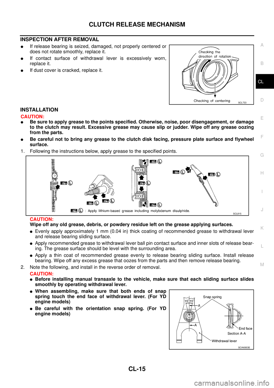
INSPECTION AFTER REMOVAL
�If release bearing is seized, damaged, not properly centered or
does not rotate smoothly, replace it.
�If contact surface of withdrawal lever is excessively worn,
replace it.
�If dust cover is cracked, replace it.
INSTALLATION
CAUTION:
�Be sure to apply grease to the points specified. Otherwise, noise, poor disengagement, or damage
to the clutch may result. Excessive grease may cause slip or judder. Wipe off any grease oozing
from the parts.
�Be careful not to bring any grease to the clutch disk facing, pressure plate surface and flywheel
surface.
1. Following the instructions below, apply grease to the specified points.
CAUTION:
Wipe off any old grease, debris, or powdery residue left on the grease applying surfaces.
�Evenly apply approximately 1 mm (0.04 in) thick coating of recommended grease to withdrawal lever
and release bearing sliding surface.
�Apply recommended grease to withdrawal lever ball pin contact surface and inner slots of release bear-
ing. The grease surface should be level with the surrounding area.
�Apply a thin coat of recommended grease evenly to release bearing sliding surface. Install release
bearing. Wipe off any excess grease that oozes from the parts and then remove release bearing.
2. Note the following, and install in the reverse order of removal.
CAUTION:
�Before installing manual transaxle to the vehicle, make sure that each sliding surface slides
smoothly by operating withdrawal lever.
�When assembling, make sure that both ends of snap
spring touch the end face of withdrawal lever. (For YD
engine models)
�Be careful with the orientation snap spring. (For YD
engine models)
SCL733
SCL815
SCIA6903E
Page 2154 of 4555
CL-18
CLUTCH DISC, CLUTCH COVER AND FLYWHEEL
INSTALLATION
1. Apply recommended grease to clutch disc and input shaft splines.
CAUTION:
Be sure to apply grease to the points specified. Otherwise, noise, poor disengagement, or damage
to the clutch may result. Excessive grease may cause slip or judder. Wipe off any grease oozing
from the parts.
2. Install clutch disc and clutch cover. Pre-tighten mounting bolts
and install clutch aligning bar.
3. Tighten clutch cover mounting bolts evenly in two steps in the
order shown in the figure. Refer to CL-16, "
COMPONENTS" .
4. Install manual transaxle. Refer to MT-19, "
Removal and Installa-
tion" . Tool number
QR engine models : KV30101600
YD engine models : KV30100100SCIA0909E
Page 2186 of 4555
MT-30
TRANSAXLE ASSEMBLY
35. Remove input shaft oil seal from clutch housing.
CAUTION:
Be careful not to damage clutch housing.
ASSEMBLY
1. Install input shaft oil seal to clutch housing using the drift.
CAUTION:
Do not reuse input shaft oil seal.
2. Install differential side oil seal until it become flush with end face
of clutch housing using the drift.
CAUTION:
�Do not reuse differential side oil seal.
�Apply multi-purpose grease onto oil seal lip. (For 4WD
models)
3. Install oil channel on mainshaft side.
CAUTION:
Be careful with the orientation of installation.
SCIA0398E
Dimension A: 1.8 - 2.8 mm (0.071 - 0.110 in)
PCIB0873E
SCIA1070J
SCIA0986E
Page 2191 of 4555

TRANSAXLE ASSEMBLY
MT-35
D
E
F
G
H
I
J
K
L
MA
B
MT
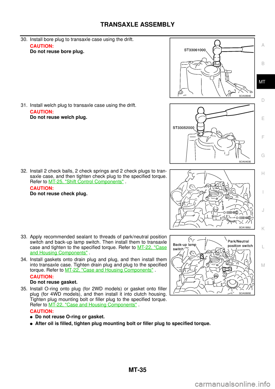
30. Install bore plug to transaxle case using the drift.
CAUTION:
Do not reuse bore plug.
31. Install welch plug to transaxle case using the drift.
CAUTION:
Do not reuse welch plug.
32. Install 2 check balls, 2 check springs and 2 check plugs to tran-
saxle case, and then tighten check plug to the specified torque.
Refer to MT-25, "
Shift Control Components" .
CAUTION:
Do not reuse check plug.
33. Apply recommended sealant to threads of park/neutral position
switch and back-up lamp switch. Then install them to transaxle
case and tighten to the specified torque. Refer to MT-22, "
Case
and Housing Components" .
34. Install gaskets onto drain plug and plug, and then install them
into transaxle case. Tighten drain plug and plug to the specified
torque. Refer to MT-22, "
Case and Housing Components" .
CAUTION:
Do not reuse gasket.
35. Install O-ring onto plug (for 2WD models) or gasket onto filler
plug (for 4WD models), and then install it into clutch housing.
Tighten plug mounting bolt or filler plug to the specified torque.
Refer to MT-22, "
Case and Housing Components" .
CAUTION:
�Do not reuse O-ring or gasket.
�After oil is filled, tighten plug mounting bolt or filler plug to specified torque.
SCIA0894E
SCIA0403E
SCIA1668J
SCIA0895E