Page 2206 of 4555

MT-50
TRANSAXLE ASSEMBLY
8. Install input shaft assembly, mainshaft assembly, and reverse
idler gear assembly into clutch housing.
CAUTION:
Be sure not to damage input shaft oil seal.
9. Install 1st-2nd bracket onto 1st-2nd fork rod, and then install
retaining pin to 1st-2nd bracket.
CAUTION:
Do not reuse retaining pin.
10. Install 1st-2nd fork rod and 1st-2nd shift fork, and then install
retaining pin to 1st-2nd shift fork.
CAUTION:
Do not reuse retaining pin.
11. Install shift check sleeve to clutch housing.
12. Install interlock pin to 3rd-4th fork rod.
13. Install 3rd-4th bracket, 3rd-4th shift fork, and 3rd-4th fork rod.
14. Install stopper rings onto 3rd-4th shift fork.
CAUTION:
Do not reuse stopper ring.
15. Install retaining pin onto 3rd-4th bracket.
CAUTION:
Do not reuse retaining pin.
16. Install 2 check balls to clutch housing.
17. Install 5th-6th bracket, 5th-6th shift fork, and 5th-6th fork rod
with interlock pin.
18. Install stopper rings onto 5th-6th bracket.
CAUTION:
Do not reuse stopper ring.
SCIA0964E
SCIA0889E
SCIA0394E
SCIA0393E
SCIA0963E
Page 2207 of 4555

TRANSAXLE ASSEMBLY
MT-51
D
E
F
G
H
I
J
K
L
MA
B
MT
19. Install retaining pin onto 5th-6th shift fork.
CAUTION:
Do not reuse retaining pin.
20. Install 2 check balls.
21. Install check ball, shift check sleeve, check spring and check
plug.
CAUTION:
�Do not reuse check plug.
�Do not drop check ball.
22. Install reverse bracket fork rod and reverse bracket.
23. Install retaining pin onto reverse bracket.
CAUTION:
Do not reuse retaining pin.
24. Install reverse shift fork and reverse fork rod.
25. Install reverse lever assembly following the procedures below.
a. Install shifter cap onto reverse lever assembly cam, and then
install them onto reverse shift fork.
CAUTION:
Do not drop shifter cap.
b. While lifting reverse shift fork, align cam with reverse bracket.
c. Install reverse lever assembly to clutch housing, and then
tighten mounting bolts to the specified torque. Refer to MT-43,
"Shift Control Components" .
26. Install check ball, shift check sleeve, check spring and check
plug to clutch housing.
CAUTION:
�Do not reuse check plug.
�Do not drop check ball.
27. Install the magnet onto clutch housing.
28. Install differential side oil seal until it is flush with end face of
transaxle case using the drift.
CAUTION:
Do not reuse differential side oil seal.
29. Install selected differential side bearing adjusting shim and dif-
ferential side bearing outer race.
�For selection of adjusting shim, refer to MT-54, "Differential
Side Bearing Preload" .
30. Install selected reverse idler gear adjusting shim onto reverse
idler gear assembly.
SCIA0962E
SCIA0961E
PCIB0791E
SCIA0960E
SCIA0887E
Page 2209 of 4555

TRANSAXLE ASSEMBLY
MT-53
D
E
F
G
H
I
J
K
L
MA
B
MT
g. Tighten mounting bolts to the specified torque.
CAUTION:
Always replace bolts B as they are self-sealing bolts.
h. Apply gear oil to O-ring and install it to control assembly. Then
install control assembly to transaxle case. Tighten bolts to the
specified torque. Refer to MT-43, "
Shift Control Components" .
CAUTION:
Do not reuse O-ring.
i. Install shift check to transaxle case, and then tighten shift check to the specified torque. Refer to MT-43,
"Shift Control Components" .
CAUTION:
Does not reuse shift check.
j. Install stopper bolt to transaxle case, and then tighten stopper bolt to the specified torque. Refer to MT-43,
"Shift Control Components" .
CAUTION:
Do not reuse stopper bolt.
34. Install bore plug to transaxle case using the drift.
CAUTION:
Do not reuse bore plug.
35. Install welch plug to transaxle case using the drift.
CAUTION:
Do not reuse welch plug.
36. Install 2 check balls, 2 check springs and 2 check plugs to tran-
saxle case, and then tighten check plug to the specified torque.
Refer to MT-43, "
Shift Control Components" .
CAUTION:
Do not reuse check plug.Bolt A:
: 52 N·m (5.3 kg-m, 38 ft-lb)
Bolt B:
: 65 N·m (6.6 kg-m, 48 ft-lb)
SCIA1064E
SCIA0894E
SCIA0403E
SCIA1667E
Page 2216 of 4555

MT-60
INPUT SHAFT AND GEARS
Synchronizer
Check items below. If necessary, replace them with new ones.
�Damage and excessive wear of contact surfaces of coupling
sleeve, synchronizer hub and shifting insert
�Coupling sleeve and synchronizer hub must move smoothly.
�If any crack, damage, or excessive wear is found on cam face of
baulk ring or working face of insert, replace it.
BAULK RING CLEARANCE
�Single-cone synchronizer (4th and 5th)
Push baulk ring on the cone, and measure the clearance
between baulk ring and cone. If measurement is below limit,
replace it with a new one.
�Double-cone synchronizer (3rd)
Check the clearance between outer baulk ring, synchronizer
cone and inner baulk ring as follows.
CAUTION:
The clearances “A” and “B” are controlled with outer baulk
ring, synchronizer cone and inner baulk ring as a set.
Replace them as a set if the clearances are outside the limit
value.
SMT387A
SMT867D
Clearance
Standard value
4th : 0.9 - 1.45 mm (0.035 - 0.057 in)
5th : 0.95 - 1.4 mm (0.037 - 0.055 in)
Limit value : 0.7 mm (0.028 in)
SMT140
SCIA0950E
Page 2218 of 4555
MT-62
INPUT SHAFT AND GEARS
ASSEMBLY
1. Install 3rd needle bearing to input shaft.
2. Install 3rd input gear and 3rd baulk ring to input shaft.
3. Install 3rd-4th spread spring, 3rd-4th shifting insert and 3rd-4th synchronizer hub onto 3rd-4th coupling
sleeve.
CAUTION:
�Be careful with orientation of 3rd-4th synchronizer hub.
�Do not reuse 3rd-4th synchronizer hub.
�Be careful with orientation of 3rd-4th coupling sleeve.
�Do not reuse 3rd-4th coupling sleeve.
�Be sure not to hook center projection of 2 spread springs
on same shifting insert.
4. Press in 3rd-4th synchronizer hub assembly using the press
stand.
CAUTION:
Align grooves of 3rd-4th shifting insert and 3rd outer baulk
ring.
SCIA0921E
PCIB0799E
SCIA1083E
SCIA0922E
Page 2219 of 4555
INPUT SHAFT AND GEARS
MT-63
D
E
F
G
H
I
J
K
L
MA
B
MT
5. Press in 4th input gear bushing using the press stand.
6. Install 4th baulk ring.
7. Install 4th needle bearing and 4th input gear to input shaft.
8. Select thrust washer so that dimension “C2” satisfies the stan-
dard value below. Then install thrust washer onto input shaft.
Refer to MT-106, "
INPUT SHAFT THRUST WASHER" .
CAUTION:
Only one thrust washer can be selected.
9. Press in 5th input gear bushing using the press stand.
CAUTION:
Do not reuse 5th input gear bushing.
10. Install 5th needle bearing and 5th input gear to input shaft.
11. Install 5th baulk ring.
12. Install 5th synchronizer hub and 5th spread spring, 5th shifting insert onto 5th coupling sleeve.
PCIB0800E
Standard for dimension C2
: 154.7 - 154.8 mm (6.091 - 6.094 in)
SCIA0925E
SCIA0926E
Page 2220 of 4555
MT-64
INPUT SHAFT AND GEARS
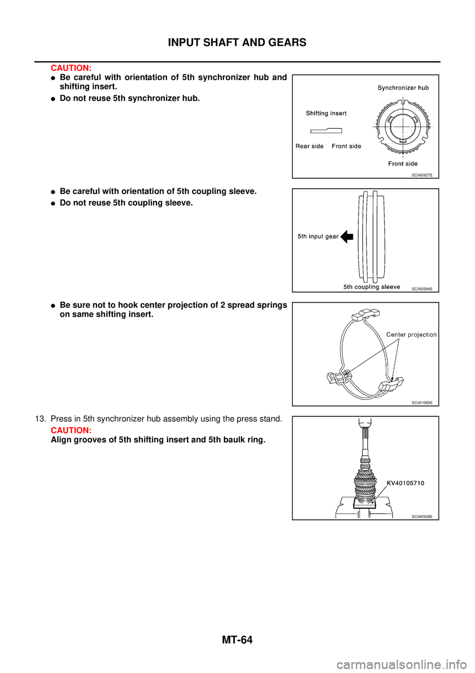
CAUTION:
�Be careful with orientation of 5th synchronizer hub and
shifting insert.
�Do not reuse 5th synchronizer hub.
�Be careful with orientation of 5th coupling sleeve.
�Do not reuse 5th coupling sleeve.
�Be sure not to hook center projection of 2 spread springs
on same shifting insert.
13. Press in 5th synchronizer hub assembly using the press stand.
CAUTION:
Align grooves of 5th shifting insert and 5th baulk ring.
SCIA0927E
SCIA0994E
SCIA1083E
SCIA0928E
Page 2223 of 4555
INPUT SHAFT AND GEARS
MT-67
D
E
F
G
H
I
J
K
L
MA
B
MT
9. Press out 5th input gear bushing, thrust washer, 4th input gear,
4th needle bearing, 4th input gear bushing, 3rd-4th synchronizer
hub assembly and 3rd input gear using the drift and a puller.
10. Remove 3rd needle bearing.
11. Press out input shaft front bearing using a puller.
INSPECTION AFTER DISASSEMBLY
Input Shaft and Gears
Check items below. If necessary, replace them with new ones.
�Damage, peeling, dent, uneven wear, bending, etc. of shaft
�Excessive wear, damage, peeling, etc. of gears
Synchronizer
Check items below. If necessary, replace them with new ones.
�Damage and excessive wear of contact surfaces of coupling
sleeve, synchronizer hub and shifting insert
�Coupling sleeve and synchronizer hub must move smoothly.
SCIA0919E
SCIA0920E
SCIA1074J
SMT387A