Page 3774 of 4555
GW-60
POWER WINDOW SYSTEM
Power Window Main Switch Power Supply and Ground Circuit CheckEIS008BC
1. CHECK POWER SUPPLY CIRCUIT
1. Turn ignition switch ON.
2. Check voltage between power window main switch connector
D7 terminal 5, 12 (LHD) or 3, 12 (RHD) and ground.
OK or NG
OK >> GO TO 2.
NG >> Repair or replace harness between power window main switch power supply circuit.
2. CHECK POWER WINDOW MAIN SWITCH GROUND CIRCUIT
1. Turn ignition switch OFF.
2. Disconnect power window main switch connector.
3. Check continuity between power window main switch connector
D6 terminal 19 and ground.
OK or NG
OK >> Power window main switch power supply and ground
circuit is OK.
NG >> Repair or replace harness between power window main
switch and ground. (LHD models)
5 (W) - Ground : Battery voltage
12 (W/R) - Ground : Battery voltage
(RHD models)
3 (W) - Ground : Battery voltage
12 (W/R) - Ground : Battery voltage
PIIA9576E
19 (B) - Ground : Continuity should exist.
PIIA9577E
Page 3775 of 4555
POWER WINDOW SYSTEM
GW-61
C
D
E
F
G
H
J
K
L
MA
B
GW
Power Window Motor (Driver side) Circuit CheckEIS008BD
1. CHECK POWER WINDOW MAIN SWITCH SIGNAL
1. Turn ignition switch ON.
2. Driver side switch in power window main switch operated, check voltage between
Power window main switch connector and ground.
(LHD)
(RHD)
OK or NG
OK >> GO TO 2.
NG >> Replace power window main switch.
Connector Terminal (Wire color)
ConditionVoltage (V)
(Approx.)
(+) (-)
D71 (L)
GroundClosing 0
Opening Battery voltage
2 (G/B) Closing Battery voltage
Opening 0
PIIA9578E
ConnectorTerminal (Wire color)
Condition Voltage (V)
(+) (-)
D7 6 (G/B)
GroundClosing Battery voltage
Opening 0
7 (L)Closing 0
Opening Battery voltage
PIIA9579E
Page 3776 of 4555

GW-62
POWER WINDOW SYSTEM
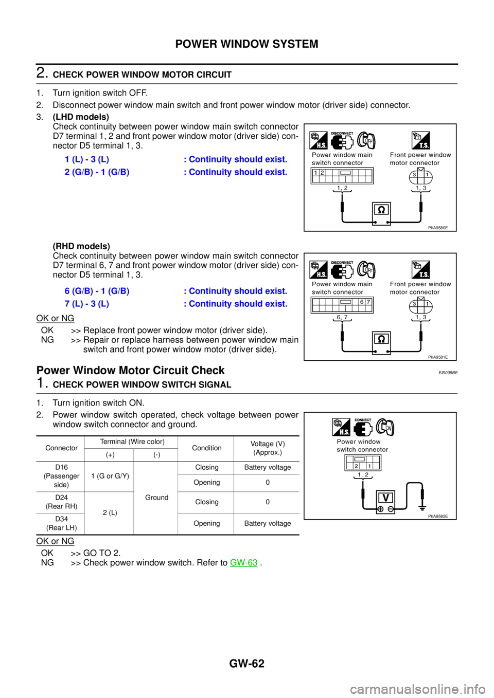
2. CHECK POWER WINDOW MOTOR CIRCUIT
1. Turn ignition switch OFF.
2. Disconnect power window main switch and front power window motor (driver side) connector.
3.(LHD models)
Check continuity between power window main switch connector
D7 terminal 1, 2 and front power window motor (driver side) con-
nector D5 terminal 1, 3.
(RHD models)
Check continuity between power window main switch connector
D7 terminal 6, 7 and front power window motor (driver side) con-
nector D5 terminal 1, 3.
OK or NG
OK >> Replace front power window motor (driver side).
NG >> Repair or replace harness between power window main
switch and front power window motor (driver side).
Power Window Motor Circuit CheckEIS008BE
1. CHECK POWER WINDOW SWITCH SIGNAL
1. Turn ignition switch ON.
2. Power window switch operated, check voltage between power
window switch connector and ground.
OK or NG
OK >> GO TO 2.
NG >> Check power window switch. Refer to GW-63
. 1 (L) - 3 (L) : Continuity should exist.
2 (G/B) - 1 (G/B) : Continuity should exist.
PIIA9580E
6 (G/B) - 1 (G/B) : Continuity should exist.
7 (L) - 3 (L) : Continuity should exist.
PIIA9581E
ConnectorTerminal (Wire color)
ConditionVoltage (V)
(Approx.)
(+) (-)
D16
(Passenger
side)1 (G or G/Y)
GroundClosing Battery voltage
Opening 0
D24
(Rear RH)
2 (L) Closing 0
D34
(Rear LH)Opening Battery voltage
PIIA9582E
Page 3777 of 4555

POWER WINDOW SYSTEM
GW-63
C
D
E
F
G
H
J
K
L
MA
B
GW
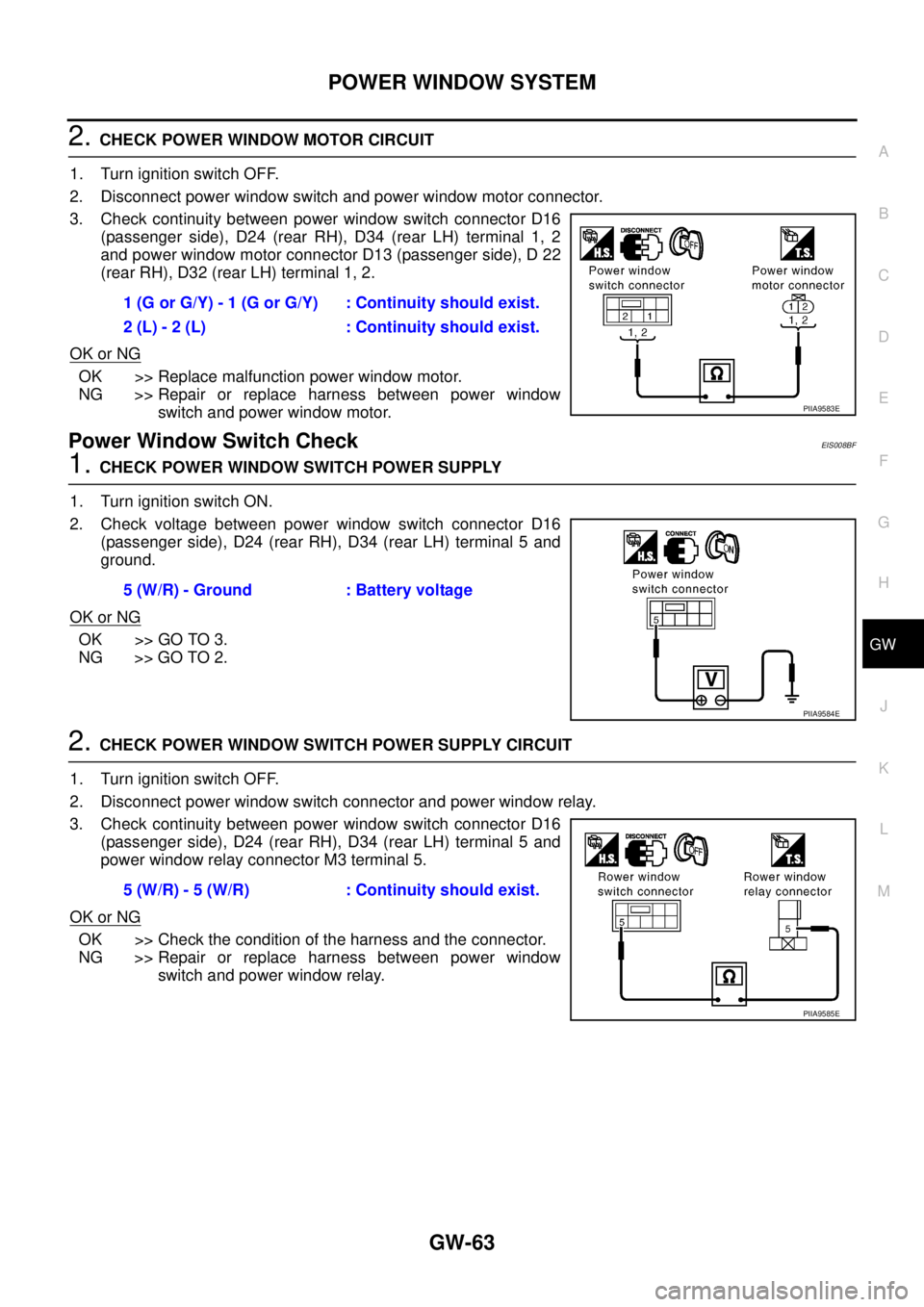
2. CHECK POWER WINDOW MOTOR CIRCUIT
1. Turn ignition switch OFF.
2. Disconnect power window switch and power window motor connector.
3. Check continuity between power window switch connector D16
(passenger side), D24 (rear RH), D34 (rear LH) terminal 1, 2
and power window motor connector D13 (passenger side), D 22
(rear RH), D32 (rear LH) terminal 1, 2.
OK or NG
OK >> Replace malfunction power window motor.
NG >> Repair or replace harness between power window
switch and power window motor.
Power Window Switch CheckEIS008BF
1. CHECK POWER WINDOW SWITCH POWER SUPPLY
1. Turn ignition switch ON.
2. Check voltage between power window switch connector D16
(passenger side), D24 (rear RH), D34 (rear LH) terminal 5 and
ground.
OK or NG
OK >> GO TO 3.
NG >> GO TO 2.
2. CHECK POWER WINDOW SWITCH POWER SUPPLY CIRCUIT
1. Turn ignition switch OFF.
2. Disconnect power window switch connector and power window relay.
3. Check continuity between power window switch connector D16
(passenger side), D24 (rear RH), D34 (rear LH) terminal 5 and
power window relay connector M3 terminal 5.
OK or NG
OK >> Check the condition of the harness and the connector.
NG >> Repair or replace harness between power window
switch and power window relay. 1 (G or G/Y) - 1 (G or G/Y) : Continuity should exist.
2 (L) - 2 (L) : Continuity should exist.
PIIA9583E
5 (W/R) - Ground : Battery voltage
PIIA9584E
5 (W/R) - 5 (W/R) : Continuity should exist.
PIIA9585E
Page 3778 of 4555

GW-64
POWER WINDOW SYSTEM
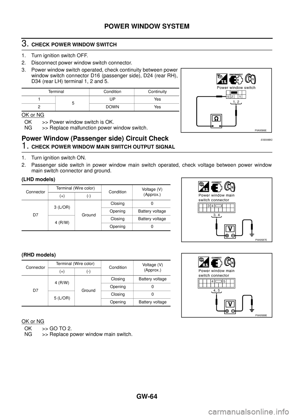
3. CHECK POWER WINDOW SWITCH
1. Turn ignition switch OFF.
2. Disconnect power window switch connector.
3. Power window switch operated, check continuity between power
window switch connector D16 (passenger side), D24 (rear RH),
D34 (rear LH) terminal 1, 2 and 5.
OK or NG
OK >> Power window switch is OK.
NG >> Replace malfunction power window switch.
Power Window (Passenger side) Circuit CheckEIS008BG
1. CHECK POWER WINDOW MAIN SWITCH OUTPUT SIGNAL
1. Turn ignition switch ON.
2. Passenger side switch in power window main switch operated, check voltage between power window
main switch connector and ground.
(LHD models)
(RHD models)
OK or NG
OK >> GO TO 2.
NG >> Replace power window main switch.
Terminal Condition Continuity
1
5UP Yes
2DOWNYes
PIIA9586E
Connector Terminal (Wire color)
ConditionVoltage (V)
(Approx.)
(+) (-)
D73 (L/OR)
GroundClosing 0
Opening Battery voltage
4 (R/W) Closing Battery voltage
Opening 0
PIIA9587E
ConnectorTerminal (Wire color)
ConditionVoltage (V)
(Approx.)
(+) (-)
D74 (R/W)
GroundClosing Battery voltage
Opening 0
5 (L/OR)Closing 0
Opening Battery voltage
PIIA9588E
Page 3779 of 4555
POWER WINDOW SYSTEM
GW-65
C
D
E
F
G
H
J
K
L
MA
B
GW
2. CHECK POWER WINDOW SWITCH CIRCUIT
1. Turn ignition switch OFF.
2. Disconnect power window main switch and font power window switch (passenger side) connector.
3.(LHD models)
Check continuity between power window main switch connector
D6 terminal 3, 4 and front power window switch (passenger
side) connector D16 terminal 3, 4.
(RHD models)
Check continuity between power window main switch connector
D6 terminal 4, 5 and front power window switch (passenger
side) connector D16 terminal 3, 4.
OK or NG
OK >> Check the condition of the harness and the connector.
NG >> Repair or replace harness between power window main
switch and front power window switch (passenger side). 3 (L/OR) - 4 (L/OR) : Continuity should exist.
4 (R/W) - 3 (R/W) : Continuity should exist.
PIIA9589E
4 (RW) - 3 (R/W) : Continuity should exist.
5 (L/OR) - 4 (L/OR) : Continuity should exist.
PIIA9590E
Page 3780 of 4555
GW-66
POWER WINDOW SYSTEM
Power Window (Rear LH) Circuit CheckEIS008BH
1. CHECK POWER WINDOW MAIN SWITCH OUTPUT SIGNAL
1. Turn ignition switch ON.
2. Rear LH switch in power window main switch operated, check voltage between power window main
switch connector and ground.
(LHD models)
(RHD models)
OK or NG
OK >> GO TO 2.
NG >> Replace power window main switch.
Connector Terminal (Wire color)
ConditionVoltage (V)
(Approx.)
(+) (-)
D714 (G/W)
GroundClosing Battery voltage
Opening 0
15 (G)Closing 0
Opening Battery voltage
PIIA9591E
Connector Terminal (Wire color)
ConditionVoltage (V)
(Approx.)
(+) (-)
D713 (G/W)
GroundClosing Battery voltage
Opening 0
14 (G) Closing 0
Opening Battery voltage
PIIA9592E
Page 3781 of 4555
POWER WINDOW SYSTEM
GW-67
C
D
E
F
G
H
J
K
L
MA
B
GW
2. CHECK POWER WINDOW SWITCH CIRCUIT
1. Turn ignition switch OFF.
2. Disconnect power window main switch and rear power window switch LH connector.
3.(LHD models)
Check continuity between power window main switch connector
D7 terminal 14, 15 and rear power window switch LH connector
D34 terminal 3, 4.
(RHD models)
Check continuity between power window main switch connector
D7 terminal 13, 14 and rear power window switch LH connector
D34 terminal 3, 4.
OK or NG
OK >> Check the condition of the harness and the connector.
NG >> Repair or replace harness between power window main
switch and rear power window switch LH. 14 (G/W) - 3 (G/W) : Continuity should exist.
15 (G) - 4 (G) : Continuity should exist.
PIIA9593E
13 (G/W) - 3 (G/W) : Continuity should exist.
14 (G) - 4 (G) : Continuity should exist.
PIIA9594E