Page 3798 of 4555
GW-84
REAR DOOR GLASS AND REGULATOR
6. Using a slotted screwdriver or similar tool, remove clip on the
corner inner cover. Slide upper hook to remove, and remove the
cover.
7. Slide the corner inner cover sash cover forward to remove.
8. Remove corner outer cover mounting bolts. Disconnect upper
hook, and remove the cover.
9. Remove mounting nuts on upper portion of rear lower sash.
10. Remove mounting bolts from lower portion of rear lower sash.
11. Rotate rear lower sash, and remove door window from glass
run.
12. Pull out the door window toward the outside of the door to
remove.
13. Remove glass run from rear lower sash.
14. Remove rear lower sash.
15. Disconnect power window motor connector.
SIIA0132E
SIIA0140E
SIIA0133E
SIIA0134E
Page 3799 of 4555

REAR DOOR GLASS AND REGULATOR
GW-85
C
D
E
F
G
H
J
K
L
MA
B
GW
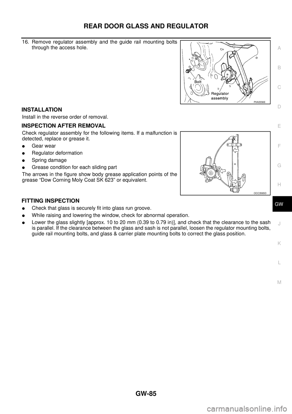
16. Remove regulator assembly and the guide rail mounting bolts
through the access hole.
INSTALLATION
Install in the reverse order of removal.
INSPECTION AFTER REMOVAL
Check regulator assembly for the following items. If a malfunction is
detected, replace or grease it.
�Gear wear
�Regulator deformation
�Spring damage
�Grease condition for each sliding part
The arrows in the figure show body grease application points of the
grease “Dow Corning Moly Coat SK 623” or equivalent.
FITTING INSPECTION
�Check that glass is securely fit into glass run groove.
�While raising and lowering the window, check for abnormal operation.
�Lower the glass slightly [approx. 10 to 20 mm (0.39 to 0.79 in)], and check that the clearance to the sash
is parallel. If the clearance between the glass and sash is not parallel, loosen the regulator mounting bolts,
guide rail mounting bolts, and glass & carrier plate mounting bolts to correct the glass position.
PIIA0556E
OCC3565D
Page 3848 of 4555
EI-22
DOOR OUTSIDE MOLDING
DOOR OUTSIDE MOLDING PFP:82820
Removal and InstallationEIS0015E
REMOVAL
Front door outside molding
1. Roll the front door window all the way up.
2. Remove front door finisher. Refer to EI-32, "
Removal and Installation" .
3. Remove corner cover and door mirror. Refer to GW-91, "
Removal and Installation" .
4. Disengage front door outside molding pawl.
5. Reaching from inner side of door, use a clip clamp tool to disen-
gage front door outside molding from the pawl.
NOTE:
Insert clip clamp tool into the door tab, then disengage by press-
ing in the direction of arrow. (See figure on the right.)
Rear door outside molding
1. Roll the rear door window all the way up.
2. Remove rear door finisher. Refer to EI-32, "
Removal and Installation" .
3. Remove corner inner cover and corner outer cover. Refer to GW-83, "
Removal and Installation" .
4. Disengage rear door outside mold pawl.
SIIA0201E
SIIA0202E
Page 3859 of 4555
DOOR FINISHER
EI-33
C
D
E
F
G
H
J
K
L
MA
B
EI
2. Insert a screwdriver, wrapped with a cloth, into the cutout on the
front edge of power window switch finisher. Unfasten the metal
clip on the front side.
3. Insert the screwdriver into the gap and remove metal clips, mov-
ing from front to rear.
4. Disconnect and remove power window switch connector.
5. Remove door finisher mounting screw.
6. Insert a screwdriver, wrapped with a cloth, into the cutout on the
lower part of door finisher. Unfasten the clips.
CAUTION:
�Insert a clip driver or clip clamp remover into the part
shown by the arrow (between the body side panel and the
clips). Remove finisher.
�To install the finisher, confirm clips are surely aligned with
the holes on the body side panel, then press in.
7. Pull the door finisher upwards to remove.
Installation
Installation is in the reverse order of removal.
SIIA0208J
SIIA0211J
SIIA0213J
SIIA0810E
Page 4118 of 4555

LT-122
ILLUMINATION
ILLUMINATIONPFP:27545
System Description EKS003C7
Power is supplied at all times
�through 10A fuse (No. 31, located in fuse and fusible link box)
�to lighting switch terminal 11.
The lighting switch must be in the 1ST or 2ND position for illumination.
The following chart shows the power and ground connector terminals for the components included in the illu-
mination system.
Component Connector No. Power terminal Ground terminal
Headlamp washier switch M23 4 3
Headlamp aiming switch M24 3 4
ESP off switch M25 3 4
Driving lamp switch M101 1 5
Door mirror remote control switch M26 10 3
Driver pocket lamp M119 1 2
4WD mode switch M39 5 6
Hazard switch M51 7 8
Rear window defogger switch M50 5 6
A/C auto amp. M52 12 11
Combination meter M45 60 63
Heater control panel M55 2 6
Audio unit (with cassette deck) M108 8 case ground
Audio unit (without cassette deck and
with NAVI)M47 1 case ground
Audio unit (without cassette deck and
without NAVI)M207 1 case ground
Cigarette lighter socket M301, M302 3 2
Ashtray illumination M303 5 6
A/T device M58 3 4
NAVI control unit M116, M117 25 1, 4
NAVI switch M113 2 3
Heated seat switch LH (LHD models) B212 5 6
Heated seat switch RH (LHD models) B213 5 6
Page 4417 of 4555

PG-1
POWER SUPPLY, GROUND & CIRCUIT ELEMENTS
K ELECTRICAL
CONTENTS
C
D
E
F
G
H
I
J
L
M
SECTION PG
A
B
PG
POWER SUPPLY, GROUND & CIRCUIT ELEMENTS
POWER SUPPLY ROUTING ...................................... 2
Schematic ................................................................ 2
Wiring Diagram — POWER — ................................. 3
BATTERY POWER SUPPLY — IGNITION SW.
IN ANY POSITION ................................................ 3
ACCESSORY POWER SUPPLY — IGNITION
SW. IN “ACC” OR “ON” ......................................... 7
IGNITION POWER SUPPLY — IGNITION SW.
IN “ON” AND/OR “START” .................................... 8
Fuse ....................................................................... 12
Fusible Link ............................................................ 12
Circuit Breaker ....................................................... 12
GROUND .................................................................. 13
Ground Distribution ................................................ 13
MAIN HARNESS/LHD MODELS ........................ 13
MAIN HARNESS/RHD MODELS ........................ 16
ENGINE ROOM HARNESS/LHD MODELS ....... 19
ENGINE ROOM HARNESS/RHD MODELS ....... 21
ENGINE ROOM HARNESS ................................ 23
ENGINE CONTROL HARNESS/GASOLINE
ENGINE MODELS .............................................. 24
ENGINE CONTROL HARNESS/DIESEL
ENGINE MODELS .............................................. 25
BODY HARNESS/LHD MODELS ....................... 26
BODY HARNESS/RHD MODELS ....................... 27
BODY NO. 2 HARNESS/LHD MODELS ............. 28
BODY NO. 2 HARNESS/RHD MODELS ............ 29
ROOM LAMP HARNESS .................................... 30
BACK DOOR SUB HARNESS/REAR WINDOW
DEFOGGER HARNESS ..................................... 31
HARNESS ................................................................. 32
Harness Layout ...................................................... 32
HOW TO READ HARNESS LAYOUTS ............... 32
OUTLINE/LHD MODELS .................................... 33
OUTLINE/RHD MODELS .................................... 34
MAIN HARNESS/LHD MODELS ........................ 35MAIN HARNESS/RHD MODELS ........................ 37
ENGINE ROOM HARNESS/LHD MODELS ........ 39
ENGINE ROOM HARNESS/RHD MODELS ....... 45
ENGINE CONTROL HARNESS .......................... 51
BODY HARNESS/LHD MODELS ....................... 56
BODY HARNESS/RHD MODELS ....................... 57
BODY NO. 2 HARNESS/LHD MODELS ............. 58
BODY NO. 2 HARNESS/RHD MODELS ............. 59
ROOM LAMP HARNESS .................................... 60
FRONT DOOR HARNESS/LHD MODELS .......... 61
FRONT DOOR HARNESS/RHD MODELS ......... 62
REAR DOOR HARNESS .................................... 63
BACK DOOR HARNESS .................................... 64
Wiring Diagram Codes (Cell Codes) ...................... 65
ELECTRICAL UNITS LOCATION ............................ 69
Electrical Units Location ......................................... 69
ENGINE COMPARTMENT .................................. 69
PASSENGER COMPARTMENT/LHD MODELS ... 70
PASSENGER COMPARTMENT/RHD MODELS ... 72
HARNESS CONNECTOR ......................................... 74
Description .............................................................. 74
HARNESS CONNECTOR (TAB-LOCKING
TYPE) .................................................................. 74
HARNESS CONNECTOR (SLIDE-LOCKING
TYPE) .................................................................. 75
ELECTRICAL UNITS ................................................ 76
Terminal Arrangement ............................................ 76
STANDARDIZED RELAY .......................................... 77
Description .............................................................. 77
NORMAL OPEN, NORMAL CLOSED AND
MIXED TYPE RELAYS ........................................ 77
TYPE OF STANDARDIZED RELAYS ................. 77
FUSE BLOCK - JUNCTION BOX (J/B) .................... 79
Terminal Arrangement ............................................ 79
FUSE AND FUSIBLE LINK BOX .............................. 80
Terminal Arrangement ............................................ 80
Page 4447 of 4555
GROUND
PG-31
C
D
E
F
G
H
I
J
L
MA
B
PG
BACK DOOR SUB HARNESS/REAR WINDOW DEFOGGER HARNESS
CKIA0376E
Page 4481 of 4555

HARNESS
PG-65
C
D
E
F
G
H
I
J
L
MA
B
PG
Wiring Diagram Codes (Cell Codes) EKS0032J
Use the chart below to find out what each wiring diagram code stands for.
Refer to the wiring diagram code in the alphabetical index to find the location (page number) of each wiring
diagram.
Code Section Wiring Diagram Name
1STSIG AT A/T 1st Signal
2NDSIG AT A/T 2nd Signal
3RDSIG AT A/T 3rd Signal
4THSIG AT A/T 4th Signal
4WD TF 4WD Control system
A/C ATC Air Conditioner
ABS BRC Anti-Lock Brake System
APP1PW EC Accelerator Pedal Position Sensor 1 Power Supply
APP2PW EC Accelerator Pedal Position Sensor 2 Power Supply
APPS1 EC Accelerator Pedal Position Sensor
APPS2 EC Accelerator Pedal Position Sensor
APPS3 EC Accelerator Pedal Position Sensor
ASC/BS EC Automatic Speed Control Device (ASCD) Brake Switch
ASC/SW EC Automatic Speed Control Device (ASCD) Steering Switch
ASCBOF EC Automatic Speed Control Device (ASCD) Brake Switch
ASCIND EC Automatic Speed Control Device (ASCD) Indicator
AT/IND DI A/T Indicator Lamp
AUDIO AV Audio
BA/FTS AT A/T Fluid Temperature Sensor and TCM Power Supply
BACK/L LT Back-Up Lamp
BOOST EC Turbocharger Boost Sensor
BRK/SW EC Brake Switch
CAN AT CAN Communication Line
CAN EC CAN Communication Line
CAN LAN CAN System
CHARGE SC Charging System
CHIME DI Warning Chime
CIGAR WW Cigarette Lighter
CKPS EC Crankshaft Position Sensor
CLOCK DI Clock
CMPS EC Camshaft Position Sensor
COOL/F EC Cooling Fan Control
D/LOCK BL Power Door Lock
DEF GW Rear Window Defogger
DTRL LT Headlamp - With Daytime Light System
ECM/PW EC ECM Power Supply for Back-Up
ECMRLY EC ECM Relay
ECTS EC Engine Coolant Temperature Sensor
EGRVLV EC EGR Volume Control Valve
EGVC/V EC EGR Volume Control Valve
ENGSS AT Engine Speed Signal