Page 1287 of 4555
IGNITION SIGNAL
EC-883
[QR (WITHOUT EURO-OBD)]
C
D
E
F
G
H
I
J
K
L
MA
EC
IGNITION COIL WITH POWER TRANSISTOR
1. Turn ignition switch OFF.
2. Disconnect ignition coil harness connector.
3. Check resistance between ignition coil terminals as follows.
Removal and InstallationEBS01141
IGNITION COIL WITH POWER TRANSISTOR
Refer to EM-31, "IGNITION COIL" .
Terminal No. Resistance Ω [at 25°C (77°F)]
2 and 3 Except 0 or ∞
1 and 2
Except 0
1 and 3
MBIB0032E
Page 1393 of 4555
![NISSAN X-TRAIL 2005 Service Repair Manual ENGINE CONTROL SYSTEM
EC-989
[YD (WITH EURO-OBD)]
C
D
E
F
G
H
I
J
K
L
MA
EC
Crankcase Ventilation SystemEBS01170
DESCRIPTION
In this system, blow-by gas is sucked into the air duct after oil separat](/manual-img/5/57403/w960_57403-1392.png "NISSAN X-TRAIL 2005 Service Repair Manual ENGINE CONTROL SYSTEM
EC-989
[YD (WITH EURO-OBD)]
C
D
E
F
G
H
I
J
K
L
MA
EC
Crankcase Ventilation SystemEBS01170
DESCRIPTION
In this system, blow-by gas is sucked into the air duct after oil separat")
ENGINE CONTROL SYSTEM
EC-989
[YD (WITH EURO-OBD)]
C
D
E
F
G
H
I
J
K
L
MA
EC
Crankcase Ventilation SystemEBS01170
DESCRIPTION
In this system, blow-by gas is sucked into the air duct after oil separation by oil separator in the rocker cover.
INSPECTION
Ventilation Hose
1. Check hoses and hose connections for leaks.
2. Disconnect all hoses and clean with compressed air. If any hose
cannot be freed of obstructions, replace.
CAN CommunicationEBS01171
SYSTEM DESCRIPTION
CAN (Controller Area Network) is a serial communication line for real time application. It is an on-vehicle mul-
tiplex communication line with high data communication speed and excellent error detection ability. Many elec-
tronic control units are equipped onto a vehicle, and each control unit shares information and links with other
control units during operation (not independent). In CAN communication, control units are connected with 2
communication lines (CAN H line, CAN L line) allowing a high rate of information transmission with less wiring.
Each control unit transmits/receives data but selectively reads required data only.
CAN COMMUNICATION UNIT
Go to CAN system, when selecting your CAN system type from the following table.
PBIB0590E
SEC692
Body typeWagon
Axle 4WD 2WD
EngineYD22DDTi
TransmissionM/T
Brake control ABS ESP ABS ESP
ECM×××
ESP/TCS/ABS control unit××
ABS actuator and electric unit (control unit)××
Page 1566 of 4555
EC-1162
[YD (WITH EURO-OBD)]
DTC P0335 CKP SENSOR
6. CHECK INTERMITTENT INCIDENT
Refer to EC-1045, "
TROUBLE DIAGNOSIS FOR INTERMITTENT INCIDENT" .
>>INSPECTION END
Component InspectionEBS011B1
CRANKSHAFT POSITION SENSOR
1. Loosen the fixing bolt of the sensor.
2. Disconnect crankshaft position sensor harness connector.
3. Remove the sensor.
4. Visually check the sensor for chipping.
5. Check resistance as shown in the figure.
6. If NG, replace crankshaft position sensor.
Removal and InstallationEBS011B2
CRANKSHAFT POSITION SENSOR
Refer to EM-157, "OIL PAN AND OIL STRAINER" .
MBIB0864E
Terminal No. (Polarity) Resistance Ω [at 25°C (77°F)]
1 (+) - 2 (-) Except 0
1 (+) - 3 (-) Except 0 or ∞
2 (+) - 3 (-) Except 0
MBIB1009E
Page 1572 of 4555
EC-1168
[YD (WITH EURO-OBD)]
DTC P0336 CKP SENSOR
6. CHECK GEAR TOOTH
Visually check for chipping signal plate gear tooth.
OK or NG
OK >> GO TO 7.
NG >> Replace the signal plate.
7. CHECK INTERMITTENT INCIDENT
Refer to EC-1045, "
TROUBLE DIAGNOSIS FOR INTERMITTENT INCIDENT" .
>>INSPECTION END
Component InspectionEBS011BA
CRANKSHAFT POSITION SENSOR
1. Loosen the fixing bolt of the sensor.
2. Disconnect crankshaft position sensor harness connector.
3. Remove the sensor.
4. Visually check the sensor for chipping.
5. Check resistance as shown in the figure.
6. If NG, replace crankshaft position sensor.
Removal and InstallationEBS011BB
CRANKSHAFT POSITION SENSOR
Refer to EM-157, "OIL PAN AND OIL STRAINER" .
MBIB0864E
Terminal No. (Polarity) Resistance Ω [at 25°C (77°F)]
1 (+) - 2 (-) Except 0
1 (+) - 3 (-) Except 0 or ∞
2 (+) - 3 (-) Except 0
MBIB1009E
Page 1769 of 4555
![NISSAN X-TRAIL 2005 Service Repair Manual ENGINE CONTROL SYSTEM
EC-1365
[YD (WITHOUT EURO-OBD)]
C
D
E
F
G
H
I
J
K
L
MA
EC
Crankcase Ventilation SystemEBS011X4
DESCRIPTION
In this system, blow-by gas is sucked into the air duct after oil sep](/manual-img/5/57403/w960_57403-1768.png "NISSAN X-TRAIL 2005 Service Repair Manual ENGINE CONTROL SYSTEM
EC-1365
[YD (WITHOUT EURO-OBD)]
C
D
E
F
G
H
I
J
K
L
MA
EC
Crankcase Ventilation SystemEBS011X4
DESCRIPTION
In this system, blow-by gas is sucked into the air duct after oil sep")
ENGINE CONTROL SYSTEM
EC-1365
[YD (WITHOUT EURO-OBD)]
C
D
E
F
G
H
I
J
K
L
MA
EC
Crankcase Ventilation SystemEBS011X4
DESCRIPTION
In this system, blow-by gas is sucked into the air duct after oil separation by oil separator in the rocker cover.
INSPECTION
Ventilation Hose
1. Check hoses and hose connections for leaks.
2. Disconnect all hoses and clean with compressed air. If any hose
cannot be freed of obstructions, replace.
CAN CommunicationEBS01H7B
SYSTEM DESCRIPTION
CAN (Controller Area Network) is a serial communication line for real time application. It is an on-vehicle mul-
tiplex communication line with high data communication speed and excellent error detection ability. Many elec-
tronic control units are equipped onto a vehicle, and each control unit shares information and links with other
control units during operation (not independent). In CAN communication, control units are connected with 2
communication lines (CAN H line, CAN L line) allowing a high rate of information transmission with less wiring.
Each control unit transmits/receives data but selectively reads required data only.
CAN COMMUNICATION UNIT
Go to CAN system, when selecting your CAN system type from the following table.
PBIB0590E
SEC692
Body typeWagon
Axle 4WD 2WD
EngineYD22DDTi
TransmissionM/T
Brake control ABS ESP ABS ESP
ECM×××
ESP/TCS/ABS control unit××
ABS actuator and electric unit (control unit)××
Page 1921 of 4555
DTC P0335 CKP SENSOR
EC-1517
[YD (WITHOUT EURO-OBD)]
C
D
E
F
G
H
I
J
K
L
MA
EC
6. CHECK INTERMITTENT INCIDENT
Refer to EC-1414, "
TROUBLE DIAGNOSIS FOR INTERMITTENT INCIDENT" .
>>INSPECTION END
Component InspectionEBS0121A
CRANKSHAFT POSITION SENSOR
1. Loosen the fixing bolt of the sensor.
2. Disconnect crankshaft position sensor harness connector.
3. Remove the sensor.
4. Visually check the sensor for chipping.
5. Check resistance as shown in the figure.
6. If NG, replace crankshaft position sensor.
Removal and InstallationEBS0121B
CRANKSHAFT POSITION SENSOR
Refer to EM-157, "OIL PAN AND OIL STRAINER" .
MBIB0864E
Terminal No. (Polarity) Resistance Ω [at 25°C (77°F)]
1 (+) - 2 (-) Except 0
1 (+) - 3 (-) Except 0 or ∞
2 (+) - 3 (-) Except 0
MBIB1009E
Page 1928 of 4555
EC-1524
[YD (WITHOUT EURO-OBD)]
DTC P0336 CKP SENSOR
6. CHECK GEAR TOOTH
Visually check for chipping signal plate gear tooth.
OK or NG
OK >> GO TO 7.
NG >> Replace the signal plate.
7. CHECK INTERMITTENT INCIDENT
Refer to EC-1414, "
TROUBLE DIAGNOSIS FOR INTERMITTENT INCIDENT" .
>>INSPECTION END
Component InspectionEBS0121J
CRANKSHAFT POSITION SENSOR
1. Loosen the fixing bolt of the sensor.
2. Disconnect crankshaft position sensor harness connector.
3. Remove the sensor.
4. Visually check the sensor for chipping.
5. Check resistance as shown in the figure.
6. If NG, replace crankshaft position sensor.
Removal and InstallationEBS0121K
CRANKSHAFT POSITION SENSOR
Refer to EM-157, "OIL PAN AND OIL STRAINER" .
MBIB0864E
Terminal No. (Polarity) Resistance Ω [at 25°C (77°F)]
1 (+) - 2 (-) Except 0
1 (+) - 3 (-) Except 0 or ∞
2 (+) - 3 (-) Except 0
MBIB1009E
Page 2116 of 4555
FL-10
[QR]
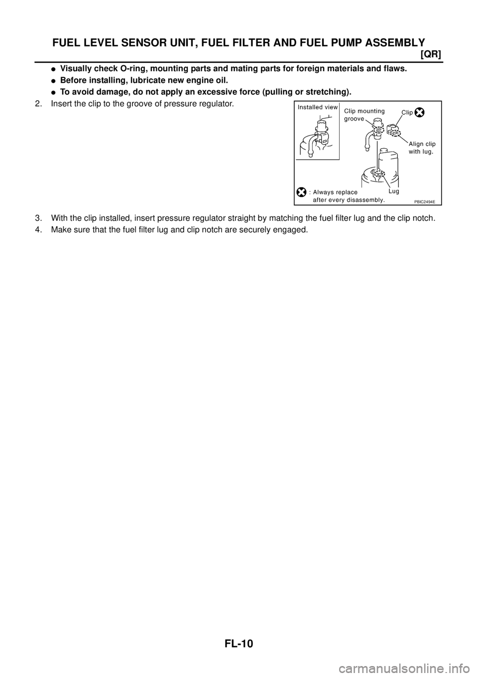
FUEL LEVEL SENSOR UNIT, FUEL FILTER AND FUEL PUMP ASSEMBLY
�Visually check O-ring, mounting parts and mating parts for foreign materials and flaws.
�Before installing, lubricate new engine oil.
�To avoid damage, do not apply an excessive force (pulling or stretching).
2. Insert the clip to the groove of pressure regulator.
3. With the clip installed, insert pressure regulator straight by matching the fuel filter lug and the clip notch.
4. Make sure that the fuel filter lug and clip notch are securely engaged.
PBIC2494E
![NISSAN X-TRAIL 2005 Service Repair Manual IGNITION SIGNAL
EC-883
[QR (WITHOUT EURO-OBD)]
C
D
E
F
G
H
I
J
K
L
MA
EC
IGNITION COIL WITH POWER TRANSISTOR
1. Turn ignition switch OFF.
2. Disconnect ignition coil harness connector.
3. Check resi](/manual-img/5/57403/w960_57403-1286.png "NISSAN X-TRAIL 2005 Service Repair Manual IGNITION SIGNAL
EC-883
[QR (WITHOUT EURO-OBD)]
C
D
E
F
G
H
I
J
K
L
MA
EC
IGNITION COIL WITH POWER TRANSISTOR
1. Turn ignition switch OFF.
2. Disconnect ignition coil harness connector.
3. Check resi")
![NISSAN X-TRAIL 2005 Service Repair Manual EC-1162
[YD (WITH EURO-OBD)]
DTC P0335 CKP SENSOR
6. CHECK INTERMITTENT INCIDENT
Refer to EC-1045, "
TROUBLE DIAGNOSIS FOR INTERMITTENT INCIDENT" .
>>INSPECTION END
Component InspectionEBS011B1
CRAN](/manual-img/5/57403/w960_57403-1565.png "NISSAN X-TRAIL 2005 Service Repair Manual EC-1162
[YD (WITH EURO-OBD)]
DTC P0335 CKP SENSOR
6. CHECK INTERMITTENT INCIDENT
Refer to EC-1045, \"
TROUBLE DIAGNOSIS FOR INTERMITTENT INCIDENT\" .
>>INSPECTION END
Component InspectionEBS011B1
CRAN")
![NISSAN X-TRAIL 2005 Service Repair Manual EC-1168
[YD (WITH EURO-OBD)]
DTC P0336 CKP SENSOR
6. CHECK GEAR TOOTH
Visually check for chipping signal plate gear tooth.
OK or NG
OK >> GO TO 7.
NG >> Replace the signal plate.
7. CHECK INTERMITTE](/manual-img/5/57403/w960_57403-1571.png "NISSAN X-TRAIL 2005 Service Repair Manual EC-1168
[YD (WITH EURO-OBD)]
DTC P0336 CKP SENSOR
6. CHECK GEAR TOOTH
Visually check for chipping signal plate gear tooth.
OK or NG
OK >> GO TO 7.
NG >> Replace the signal plate.
7. CHECK INTERMITTE")
![NISSAN X-TRAIL 2005 Service Repair Manual DTC P0335 CKP SENSOR
EC-1517
[YD (WITHOUT EURO-OBD)]
C
D
E
F
G
H
I
J
K
L
MA
EC
6. CHECK INTERMITTENT INCIDENT
Refer to EC-1414, "
TROUBLE DIAGNOSIS FOR INTERMITTENT INCIDENT" .
>>INSPECTION END
Comp](/manual-img/5/57403/w960_57403-1920.png "NISSAN X-TRAIL 2005 Service Repair Manual DTC P0335 CKP SENSOR
EC-1517
[YD (WITHOUT EURO-OBD)]
C
D
E
F
G
H
I
J
K
L
MA
EC
6. CHECK INTERMITTENT INCIDENT
Refer to EC-1414, \"
TROUBLE DIAGNOSIS FOR INTERMITTENT INCIDENT\" .
>>INSPECTION END
Comp")
![NISSAN X-TRAIL 2005 Service Repair Manual EC-1524
[YD (WITHOUT EURO-OBD)]
DTC P0336 CKP SENSOR
6. CHECK GEAR TOOTH
Visually check for chipping signal plate gear tooth.
OK or NG
OK >> GO TO 7.
NG >> Replace the signal plate.
7. CHECK INTERMI](/manual-img/5/57403/w960_57403-1927.png "NISSAN X-TRAIL 2005 Service Repair Manual EC-1524
[YD (WITHOUT EURO-OBD)]
DTC P0336 CKP SENSOR
6. CHECK GEAR TOOTH
Visually check for chipping signal plate gear tooth.
OK or NG
OK >> GO TO 7.
NG >> Replace the signal plate.
7. CHECK INTERMI")