Page 2209 of 4555
TRANSAXLE ASSEMBLY
MT-53
D
E
F
G
H
I
J
K
L
MA
B
MT
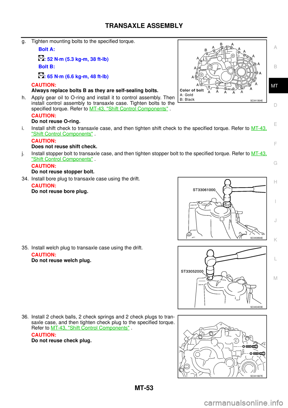
g. Tighten mounting bolts to the specified torque.
CAUTION:
Always replace bolts B as they are self-sealing bolts.
h. Apply gear oil to O-ring and install it to control assembly. Then
install control assembly to transaxle case. Tighten bolts to the
specified torque. Refer to MT-43, "
Shift Control Components" .
CAUTION:
Do not reuse O-ring.
i. Install shift check to transaxle case, and then tighten shift check to the specified torque. Refer to MT-43,
"Shift Control Components" .
CAUTION:
Does not reuse shift check.
j. Install stopper bolt to transaxle case, and then tighten stopper bolt to the specified torque. Refer to MT-43,
"Shift Control Components" .
CAUTION:
Do not reuse stopper bolt.
34. Install bore plug to transaxle case using the drift.
CAUTION:
Do not reuse bore plug.
35. Install welch plug to transaxle case using the drift.
CAUTION:
Do not reuse welch plug.
36. Install 2 check balls, 2 check springs and 2 check plugs to tran-
saxle case, and then tighten check plug to the specified torque.
Refer to MT-43, "
Shift Control Components" .
CAUTION:
Do not reuse check plug.Bolt A:
: 52 N·m (5.3 kg-m, 38 ft-lb)
Bolt B:
: 65 N·m (6.6 kg-m, 48 ft-lb)
SCIA1064E
SCIA0894E
SCIA0403E
SCIA1667E
Page 2221 of 4555
INPUT SHAFT AND GEARS
MT-65
D
E
F
G
H
I
J
K
L
MA
B
MT
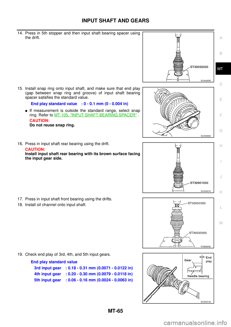
14. Press in 5th stopper and then input shaft bearing spacer using
the drift.
15. Install snap ring onto input shaft, and make sure that end play
(gap between snap ring and groove) of input shaft bearing
spacer satisfies the standard value.
�If measurement is outside the standard range, select snap
ring. Refer to MT-105, "
INPUT SHAFT BEARING SPACER" .
CAUTION:
Do not reuse snap ring.
16. Press in input shaft rear bearing using the drift.
CAUTION:
Install input shaft rear bearing with its brown surface facing
the input gear side.
17. Press in input shaft front bearing using the drifts.
18. Install oil channel onto input shaft.
19. Check end play of 3rd, 4th, and 5th input gears.
SCIA0929E
End play standard value : 0 - 0.1 mm (0 - 0.004 in)
SCIA0930E
SCIA0931E
PCIB0825E
End play standard value
3rd input gear : 0.18 - 0.31 mm (0.0071 - 0.0122 in)
4th input gear : 0.20 - 0.30 mm (0.0079 - 0.0118 in)
5th input gear : 0.06 - 0.16 mm (0.0024 - 0.0063 in)
SCIA0914E
Page 2228 of 4555
MT-72
INPUT SHAFT AND GEARS
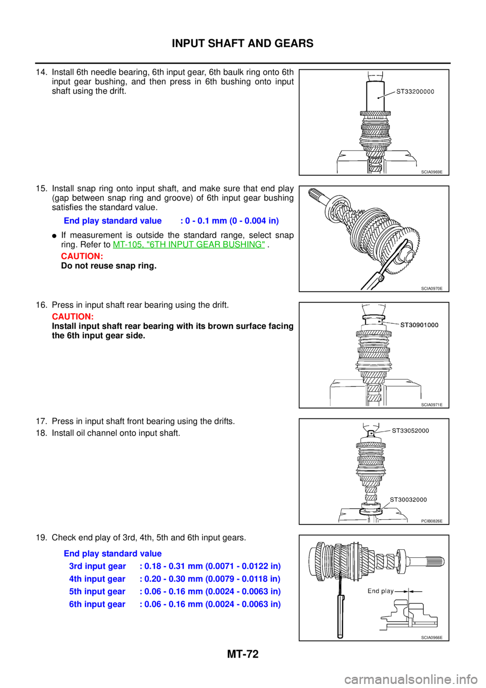
14. Install 6th needle bearing, 6th input gear, 6th baulk ring onto 6th
input gear bushing, and then press in 6th bushing onto input
shaft using the drift.
15. Install snap ring onto input shaft, and make sure that end play
(gap between snap ring and groove) of 6th input gear bushing
satisfies the standard value.
�If measurement is outside the standard range, select snap
ring. Refer to MT-105, "
6TH INPUT GEAR BUSHING" .
CAUTION:
Do not reuse snap ring.
16. Press in input shaft rear bearing using the drift.
CAUTION:
Install input shaft rear bearing with its brown surface facing
the 6th input gear side.
17. Press in input shaft front bearing using the drifts.
18. Install oil channel onto input shaft.
19. Check end play of 3rd, 4th, 5th and 6th input gears.
SCIA0969E
End play standard value : 0 - 0.1 mm (0 - 0.004 in)
SCIA0970E
SCIA0971E
PCIB0826E
End play standard value
3rd input gear : 0.18 - 0.31 mm (0.0071 - 0.0122 in)
4th input gear : 0.20 - 0.30 mm (0.0079 - 0.0118 in)
5th input gear : 0.06 - 0.16 mm (0.0024 - 0.0063 in)
6th input gear : 0.06 - 0.16 mm (0.0024 - 0.0063 in)
SCIA0966E
Page 2249 of 4555
FINAL DRIVE
MT-93
D
E
F
G
H
I
J
K
L
MA
B
MT
FINAL DRIVEPFP:38411
Disassembly and Assembly (RS5F51A)ECS008CA
PRE-INSPECTION
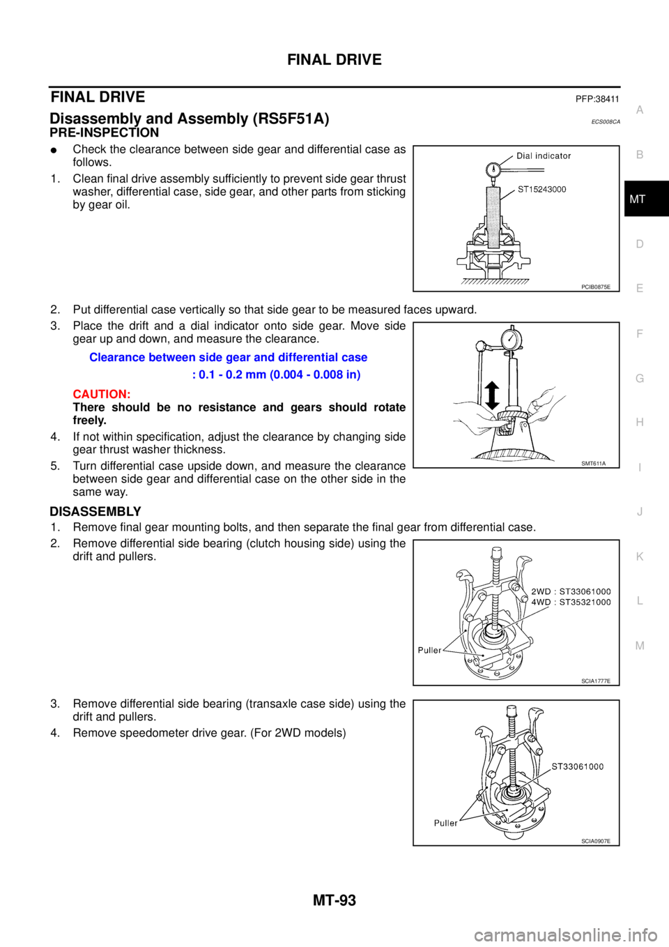
�Check the clearance between side gear and differential case as
follows.
1. Clean final drive assembly sufficiently to prevent side gear thrust
washer, differential case, side gear, and other parts from sticking
by gear oil.
2. Put differential case vertically so that side gear to be measured faces upward.
3. Place the drift and a dial indicator onto side gear. Move side
gear up and down, and measure the clearance.
CAUTION:
There should be no resistance and gears should rotate
freely.
4. If not within specification, adjust the clearance by changing side
gear thrust washer thickness.
5. Turn differential case upside down, and measure the clearance
between side gear and differential case on the other side in the
same way.
DISASSEMBLY
1. Remove final gear mounting bolts, and then separate the final gear from differential case.
2. Remove differential side bearing (clutch housing side) using the
drift and pullers.
3. Remove differential side bearing (transaxle case side) using the
drift and pullers.
4. Remove speedometer drive gear. (For 2WD models)
PCIB0875E
Clearance between side gear and differential case
: 0.1 - 0.2 mm (0.004 - 0.008 in)
SMT611A
SCIA1777E
SCIA0907E
Page 2250 of 4555
MT-94
FINAL DRIVE
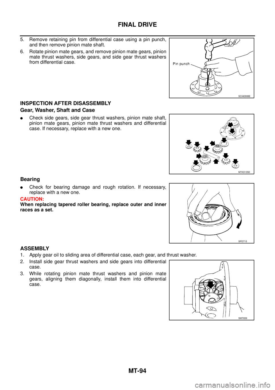
5. Remove retaining pin from differential case using a pin punch,
and then remove pinion mate shaft.
6. Rotate pinion mate gears, and remove pinion mate gears, pinion
mate thrust washers, side gears, and side gear thrust washers
from differential case.
INSPECTION AFTER DISASSEMBLY
Gear, Washer, Shaft and Case
�Check side gears, side gear thrust washers, pinion mate shaft,
pinion mate gears, pinion mate thrust washers and differential
case. If necessary, replace with a new one.
Bearing
�Check for bearing damage and rough rotation. If necessary,
replace with a new one.
CAUTION:
When replacing tapered roller bearing, replace outer and inner
races as a set.
ASSEMBLY
1. Apply gear oil to sliding area of differential case, each gear, and thrust washer.
2. Install side gear thrust washers and side gears into differential
case.
3. While rotating pinion mate thrust washers and pinion mate
gears, aligning them diagonally, install them into differential
case.
SCIA0908E
MTK0135D
SPD715
SMT839
Page 2253 of 4555
FINAL DRIVE
MT-97
D
E
F
G
H
I
J
K
L
MA
B
MT
Disassembly and Assembly (RS6F51A)ECS008CB
PRE-INSPECTION
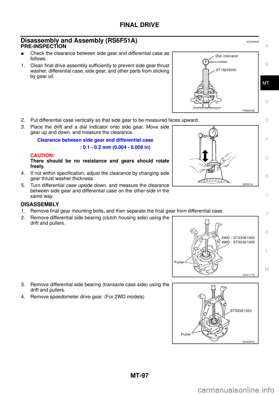
�Check the clearance between side gear and differential case as
follows.
1. Clean final drive assembly sufficiently to prevent side gear thrust
washer, differential case, side gear, and other parts from sticking
by gear oil.
2. Put differential case vertically so that side gear to be measured faces upward.
3. Place the drift and a dial indicator onto side gear. Move side
gear up and down, and measure the clearance.
CAUTION:
There should be no resistance and gears should rotate
freely.
4. If not within specification, adjust the clearance by changing side
gear thrust washer thickness.
5. Turn differential case upside down, and measure the clearance
between side gear and differential case on the other side in the
same way.
DISASSEMBLY
1. Remove final gear mounting bolts, and then separate the final gear from differential case.
2. Remove differential side bearing (clutch housing side) using the
drift and pullers.
3. Remove differential side bearing (transaxle case side) using the
drift and pullers.
4. Remove speedometer drive gear. (For 2WD models)
PCIB0875E
Clearance between side gear and differential case
: 0.1 - 0.2 mm (0.004 - 0.008 in)
SMT611A
SCIA1777E
SCIA0907E
Page 2254 of 4555
MT-98
FINAL DRIVE
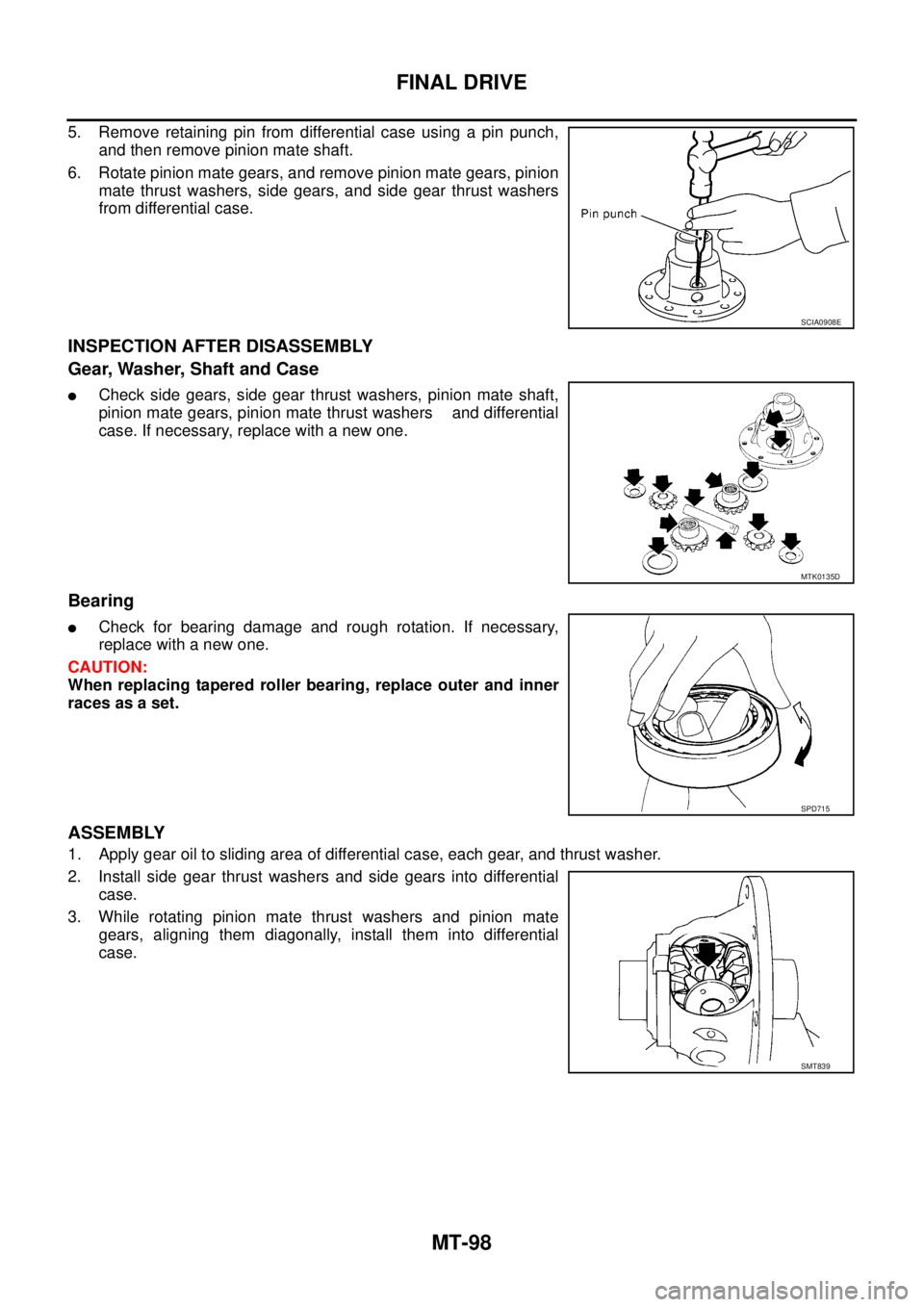
5. Remove retaining pin from differential case using a pin punch,
and then remove pinion mate shaft.
6. Rotate pinion mate gears, and remove pinion mate gears, pinion
mate thrust washers, side gears, and side gear thrust washers
from differential case.
INSPECTION AFTER DISASSEMBLY
Gear, Washer, Shaft and Case
�Check side gears, side gear thrust washers, pinion mate shaft,
pinion mate gears, pinion mate thrust washers and differential
case. If necessary, replace with a new one.
Bearing
�Check for bearing damage and rough rotation. If necessary,
replace with a new one.
CAUTION:
When replacing tapered roller bearing, replace outer and inner
races as a set.
ASSEMBLY
1. Apply gear oil to sliding area of differential case, each gear, and thrust washer.
2. Install side gear thrust washers and side gears into differential
case.
3. While rotating pinion mate thrust washers and pinion mate
gears, aligning them diagonally, install them into differential
case.
SCIA0908E
MTK0135D
SPD715
SMT839
Page 2303 of 4555

OVERALL SYSTEM
AT-39
D
E
F
G
H
I
J
K
L
MA
B
AT
Control ValveECS004QG
FUNCTION OF CONTROL VALVES
Valve name Function
Pressure regulator valve, plug and sleeve
plugRegulates oil discharged from the oil pump to provide optimum line pressure for all driv-
ing conditions.
Pressure modifier valve and sleeve Used as a signal supplementary valve to the pressure regulator valve. Regulates pres-
sure-modifier pressure (signal pressure) which controls optimum line pressure for all
driving conditions.
Pilot valve Regulates line pressure to maintain a constant pilot pressure level which controls lock-up
mechanism, overrun clutch, shift timing.
Accumulator control valve Regulates accumulator back-pressure to pressure suited to driving conditions.
Manual valve Directs line pressure to oil circuits corresponding to select positions.
Hydraulic pressure drains when the shift lever is in Neutral.
Shift valve A Simultaneously switches three oil circuits using output pressure of shift solenoid valve A
to meet driving conditions (vehicle speed, throttle opening, etc.).
Provides automatic downshifting and upshifting (1st → 2nd → 3rd → 4th gears/4th →
3rd → 2nd → 1st gears) in combination with shift valve B.
Shift valve B Simultaneously switches two oil circuits using output pressure of shift solenoid valve B in
relation to driving conditions (vehicle speed, throttle opening, etc.).
Provides automatic downshifting and upshifting (1st → 2nd → 3rd → 4th gears/4th →
3rd → 2nd → 1st gears) in combination with shift valve A.
Overrun clutch control valve Switches hydraulic circuits to prevent engagement of the overrun clutch simultaneously
with application of the brake band in D
4 . (Interlocking occurs if the overrun clutch
engages during D
4 .)
1st reducing valve Reduces low & reverse brake pressure to dampen engine-brake shock when downshift-
ing from the 1st position 1
2 to 11 .
Overrun clutch reducing valve Reduces oil pressure directed to the overrun clutch and prevents engine-brake shock.
In the 1st and 2nd positions, line pressure acts on the overrun clutch reducing valve to
increase the pressure-regulating point, with resultant engine brake capability.
Torque converter relief valve Prevents an excessive rise in torque converter pressure.
Torque converter clutch control valve, plug
and sleeveActivates or inactivates the lock-up function.
Also provides smooth lock-up through transient application and release of the lock-up
system.
1-2 accumulator valve and piston Lessens the shock find when the 2nd gear band servo contracts, and provides smooth
shifting.
3-2 timing valve Switches the pace that oil pressure is released depending on vehicle speed; maximizes
the high clutch release timing, and allows for soft downshifting.
Shuttle valve Determines if the overrun clutch solenoid valve should control the 3-2 timing valve or the
overrun clutch control valve and switches between the two.
Cooler check valve At low speeds and with a small load when a little heat is generated, saves the volume of
cooler flow, and stores the oil pressure for lock-up.