Page 2329 of 4555
TROUBLE DIAGNOSIS — BASIC INSPECTION
AT-65
[EURO-OBD]
D
E
F
G
H
I
J
K
L
MA
B
AT
Stall TestECS004QR
STALL TEST PROCEDURE
1. Check A/T fluid and engine oil levels. If necessary, add.
2. Drive vehicle for approx. 10 minutes or until fluid and oil reach
operating temperature. Refer to AT- 1 6 , "
Checking A/T Fluid" .
3. Set parking brake and block wheels.
4. Install a tachometer where it can be seen by driver during test.
�It is good practice to mark the point of specified engine
rpm on indicator.
5. Start engine, apply foot brake, and place selector lever in D
position.
6. Accelerate to wide open throttle gradually while applying foot
brake.
7. Quickly note the engine stall revolution and immediately release
throttle.
�During test, never hold throttle wide open for more than 5
seconds.
SAT647B
SAT513G
SAT775B
Stall revolution:
QR20DE: 2,450 - 2,950 rpm
QR25DE: 2,300 - 2,750 rpm
SAT514G
Page 2332 of 4555
AT-68
[EURO-OBD]
TROUBLE DIAGNOSIS — BASIC INSPECTION
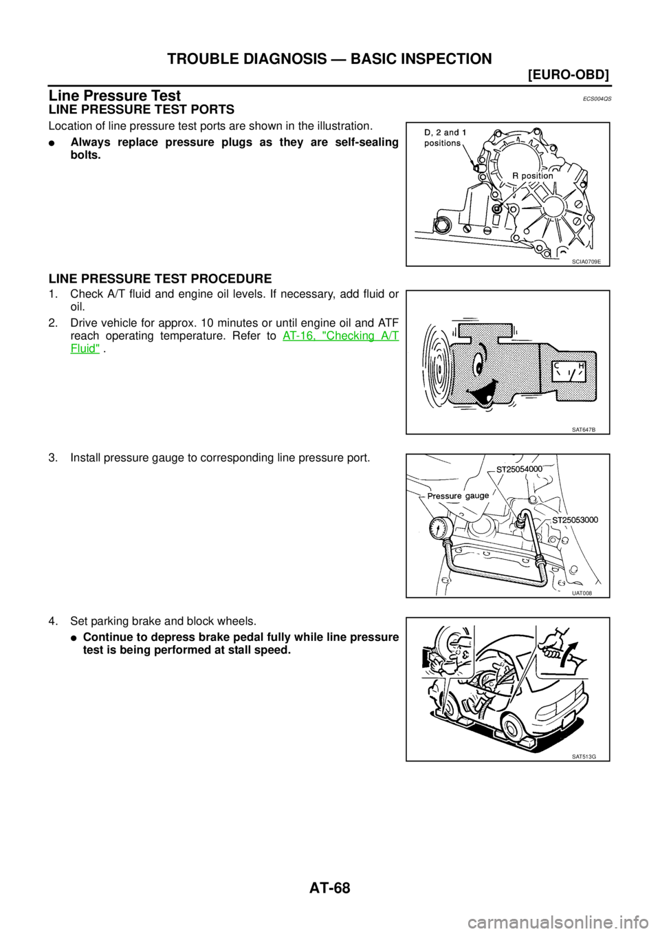
Line Pressure TestECS004QS
LINE PRESSURE TEST PORTS
Location of line pressure test ports are shown in the illustration.
�Always replace pressure plugs as they are self-sealing
bolts.
LINE PRESSURE TEST PROCEDURE
1. Check A/T fluid and engine oil levels. If necessary, add fluid or
oil.
2. Drive vehicle for approx. 10 minutes or until engine oil and ATF
reach operating temperature. Refer to AT- 1 6 , "
Checking A/T
Fluid" .
3. Install pressure gauge to corresponding line pressure port.
4. Set parking brake and block wheels.
�Continue to depress brake pedal fully while line pressure
test is being performed at stall speed.
SCIA0709E
SAT647B
UAT008
SAT513G
Page 2333 of 4555
![NISSAN X-TRAIL 2005 Service Repair Manual TROUBLE DIAGNOSIS — BASIC INSPECTION
AT-69
[EURO-OBD]
D
E
F
G
H
I
J
K
L
MA
B
AT
5. Start engine and measure line pressure at idle and stall speed.
�When measuring line pressure at stall speed, fol](/manual-img/5/57403/w960_57403-2332.png "NISSAN X-TRAIL 2005 Service Repair Manual TROUBLE DIAGNOSIS — BASIC INSPECTION
AT-69
[EURO-OBD]
D
E
F
G
H
I
J
K
L
MA
B
AT
5. Start engine and measure line pressure at idle and stall speed.
�When measuring line pressure at stall speed, fol")
TROUBLE DIAGNOSIS — BASIC INSPECTION
AT-69
[EURO-OBD]
D
E
F
G
H
I
J
K
L
MA
B
AT
5. Start engine and measure line pressure at idle and stall speed.
�When measuring line pressure at stall speed, follow the
stall test procedure.
LINE PRESSURE
JUDGEMENT OF LINE PRESSURE TEST
SAT493G
Check lock-up hold.Line pressure kPa (bar, kg/cm2 , psi)
“D”, “2” and “1” positions “R” position
Idle 500 (5.00, 5.1, 73) 778 (7.78, 7.9, 113)
Stall 1,233 (12.33, 12.6, 179) 1,918 (19.18, 19.6, 278)
Judgement Suspected parts
At idleLine pressure is low in all positions.
�Oil pump wear
�Control piston damage
�Pressure regulator valve or plug sticking
�Spring for pressure regulator valve damaged
�Fluid pressure leakage between oil strainer and pressure regulator valve
�Clogged strainer
Line pressure is low in particular posi-
tion.
�Fluid pressure leakage between manual valve and particular clutch
�For example, line pressure is:
− Low in “R” and “1” positions, but
− Normal in “D” and “2” positions.
Therefore, fluid leakage exists at or around low and reverse brake circuit.
Refer to AT- 2 3
.
Line pressure is high.
�Maladjustment of throttle position sensor
�A/T fluid temperature sensor damaged
�Line pressure solenoid valve sticking
�Short circuit of line pressure solenoid valve circuit
�Pressure modifier valve sticking
�Pressure regulator valve or plug sticking
�Open in dropping resistor circuit
At stall
speedLine pressure is low.
�Maladjustment of throttle position sensor
�Line pressure solenoid valve sticking
�Short circuit of line pressure solenoid valve circuit
�Pressure regulator valve or plug sticking
�Pressure modifier valve sticking
�Pilot valve sticking
Page 2342 of 4555
AT-78
[EURO-OBD]
TROUBLE DIAGNOSIS — BASIC INSPECTION
Cruise Test — Part 1
1. CHECK STARTING GEAR (D1 ) POSITION
1. Drive vehicle for approximately 10 minutes to warm engine oil and ATF up to operating temperature.
2. Park vehicle on flat surface.
3. Set overdrive control switch to ON position.
4. Move selector lever to “P” position.
5. Start engine.
6. Move selector lever to “D” position.
7. Accelerate vehicle by constantly depressing accelerator pedal
half-way.
Read gear position. Refer to AT- 4 6 , "
DATA MONITOR
MODE (A/T)" .
Does vehicle start from D
1 ?
YES >> GO TO 2.
NO >>
�Mark the box on the “DIAGNOSTIC WORKSHEET”.
Refer to AT- 5 8
.
�GO TO AT- 2 1 4 , "Vehicle Cannot Be Started From D1"
.
�Continue “Road Test”. ATF operating temperature: 50 - 80°C (122 - 176°F)
SAT774B
SAT775B
SAT495G
Page 2374 of 4555
![NISSAN X-TRAIL 2005 Service Repair Manual AT-110
[EURO-OBD]
DTC P0710 A/T FLUID TEMPERATURE SENSOR CIRCUIT
3. CHECK INPUT SIGNAL OF A/T FLUID TEMPERATURE SENSOR (WITHOUT CONSULT-II)
Without CONSULT-II
1. Start engine.
2. Check voltage betw](/manual-img/5/57403/w960_57403-2373.png "NISSAN X-TRAIL 2005 Service Repair Manual AT-110
[EURO-OBD]
DTC P0710 A/T FLUID TEMPERATURE SENSOR CIRCUIT
3. CHECK INPUT SIGNAL OF A/T FLUID TEMPERATURE SENSOR (WITHOUT CONSULT-II)
Without CONSULT-II
1. Start engine.
2. Check voltage betw")
AT-110
[EURO-OBD]
DTC P0710 A/T FLUID TEMPERATURE SENSOR CIRCUIT
3. CHECK INPUT SIGNAL OF A/T FLUID TEMPERATURE SENSOR (WITHOUT CONSULT-II)
Without CONSULT-II
1. Start engine.
2. Check voltage between TCM connector terminal 47 and ground while warming up A/T.
3. Turn ignition switch to “OFF” position.
4. Disconnect TCM connector.
5. Check continuity between TCM connector terminal 42 and
ground.
If OK, check harness for short to ground and short to power.
OK or NG
OK >> GO TO 4.
NG >> GO TO 5.
4. CHECK DTC
Perform AT- 1 0 6 , "
DTC Confirmation Procedure" .
OK or NG
OK >>INSPECTION END
NG >> 1. Perform TCM input/output signal inspection. Refer to AT- 9 4 , "
TCM Terminals and Reference
Va l u e" .
2. If NG, recheck TCM pin terminals for damage or loose connection with harness connector.
5. CHECK A/T FLUID TEMPERATURE SENSOR WITH TERMINAL CORD ASSEMBLY
1. Turn ignition switch to OFF.
2. Disconnect terminal cord assembly harness connector in engine compartment.
3. Check resistance between terminals when A/T is cold.
4. Reinstall any part removed.
OK or NG
OK (With CONSULT-II)>>GO TO 2.
OK (Without CONSULT-II)>>GO TO 3.
NG >> 1. Remove oil pan. Refer to AT- 4 0 4 , "
COMPONENTS" .
2. Check the following items:
–A/T fluid temperature sensor
Refer to AT- 111 , "
Component Inspection" .
–Harness of terminal cord assembly for short or open Voltage:
Cold [20°C (68°F)] → Hot [80°C (176°F)]
Approximately 1.5V → 0.5V
SCIA0738E
Continuity should exist.
SCIA0739E
Resistance:
Cold [20°C (68°F)]
Approximately 2.5 kΩ
SCIA4948E
Page 2404 of 4555
![NISSAN X-TRAIL 2005 Service Repair Manual AT-140
[EURO-OBD]
DTC P0734 A/T 4TH GEAR FUNCTION
DTC P0734 A/T 4TH GEAR FUNCTIONPFP:31940
DescriptionECS004RM
�This malfunction will not be detected while the O/D OFF indicator lamp is indicating a](/manual-img/5/57403/w960_57403-2403.png "NISSAN X-TRAIL 2005 Service Repair Manual AT-140
[EURO-OBD]
DTC P0734 A/T 4TH GEAR FUNCTION
DTC P0734 A/T 4TH GEAR FUNCTIONPFP:31940
DescriptionECS004RM
�This malfunction will not be detected while the O/D OFF indicator lamp is indicating a")
AT-140
[EURO-OBD]
DTC P0734 A/T 4TH GEAR FUNCTION
DTC P0734 A/T 4TH GEAR FUNCTIONPFP:31940
DescriptionECS004RM
�This malfunction will not be detected while the O/D OFF indicator lamp is indicating another self-diagnosis
malfunction.
�This malfunction is detected when the A/T does not shift into fourth gear position or line pressure is low as
instructed by the TCM. This is not caused by electrical malfunction (circuits open or shorted) but by
mechanical malfunction such as control valve sticking, improper solenoid valve operation, malfunctioning
oil pump or torque converter clutch, etc.
CONSULT-II REFERENCE VALUE IN DATA MONITOR MODE
Remarks: Specification data are reference values.
On Board Diagnosis LogicECS00CU1
This diagnosis monitors actual gear position by checking the torque converter slip ratio calculated by TCM as
follows:
Torque converter slip ratio = A x C/B
A: Output shaft revolution signal from revolution sensor
B: Engine speed signal from ECM
C: Gear ratio determined as gear position which TCM supposes
If the actual gear position is much lower than the position (4th) supposed by TCM, the slip ratio will be much
less than normal. In case the ratio does not reach the specified value, TCM judges this diagnosis malfunction.
This malfunction will be caused when shift solenoid valve A is stuck open or shift solenoid valve B is stuck
closed.
*: P0734 is detected.
And also, this malfunction will be caused when line pressure is lower than normal same as line pressure sole-
noid valve stuck open.
Gear position 1 2 3 4
Shift solenoid valve A ON (Closed) OFF (Open) OFF (Open) ON (Closed)
Shift solenoid valve B ON (Closed) ON (Closed) OFF (Open) OFF (Open)
Monitor item Condition Specification
Line pressure solenoid valve dutySmall throttle opening
(Low line pressure)
↓
Large throttle opening
(High line pressure)Approximately 24%
↓
Approximately 95%
Gear position supposed by TCM 1 2 3 4
In case of gear position with no malfunctions 1 2 34
In case of gear position with shift solenoid valve A stuck open 2 2 33*
In case of gear position with shift solenoid valve B stuck closed 1 2 21*
Diagnostic trouble code Malfunction is detected when... Check items (Possible cause)
: A/T 4TH GR FNCTN
A/T cannot be shifted to the 4th gear posi-
tion even if electrical circuit is good.
�Shift solenoid valve A
�Shift solenoid valve B
�Line pressure solenoid valve
�Each clutch
�Hydraulic control circuit : P0734
Page 2418 of 4555
![NISSAN X-TRAIL 2005 Service Repair Manual AT-154
[EURO-OBD]
DTC P0745 LINE PRESSURE SOLENOID VALVE
DTC P0745 LINE PRESSURE SOLENOID VALVEPFP:31940
DescriptionECS004RU
The line pressure solenoid valve regulates the oil pump discharge
pressur](/manual-img/5/57403/w960_57403-2417.png "NISSAN X-TRAIL 2005 Service Repair Manual AT-154
[EURO-OBD]
DTC P0745 LINE PRESSURE SOLENOID VALVE
DTC P0745 LINE PRESSURE SOLENOID VALVEPFP:31940
DescriptionECS004RU
The line pressure solenoid valve regulates the oil pump discharge
pressur")
AT-154
[EURO-OBD]
DTC P0745 LINE PRESSURE SOLENOID VALVE
DTC P0745 LINE PRESSURE SOLENOID VALVEPFP:31940
DescriptionECS004RU
The line pressure solenoid valve regulates the oil pump discharge
pressure to suit the driving condition in response to a signal sent
from the TCM.
The line pressure duty cycle value is not consistent when the
closed throttle position switch is ON. To confirm the line pres-
sure duty cycle at low pressure, the accelerator (throttle)
should be open until the closed throttle position switch is OFF.
CONSULT-II REFERENCE VALUE IN DATA MONITOR MODE
Remarks: Specification data are reference values.
NOTE:
The line pressure duty cycle value is not consistent when the closed throttle position switch is “ON”. To confirm the line pressure duty
cycle at low pressure, the accelerator (throttle) should be open until the closed throttle position switch is “OFF”.
On Board Diagnosis LogicECS00CU7
Possible CauseECS00CU8
Check the following items.
�Harness or connector
(The solenoid circuit is open shorted.)
�Line pressure solenoid valve
DTC Confirmation ProcedureECS00CU9
NOTE:
If “DTC Confirmation Procedure” has been previously conducted, always turn ignition switch OFF and
wait at least 5 seconds before conducting the next test.
After the repair, perform the following procedure to confirm the malfunction is eliminated.
WITH CONSULT-II
1. Turn ignition switch ON and select “DATA MONITOR” mode for
“A/T” with CONSULT-II.
SCIA0735E
Monitor item Condition Specification
Line pressure solenoid valve dutySmall throttle opening
(Low line pressure)
↓
Large throttle opening
(High line pressure)Approximately 0%
↓
Approximately 95%
Diagnostic trouble code Malfunction is detected when... Check items (Possible cause)
: LINE PRESSURE S/V
TCM detects an improper voltage drop
when it tries to operate the solenoid valve.
�Harness or connectors
(The solenoid circuit is open or shorted.)
�Line pressure solenoid valve
: P0745
SAT014K
Page 2454 of 4555
![NISSAN X-TRAIL 2005 Service Repair Manual AT-190
[EURO-OBD]
DTC BATT/FLUID TEMP SEN (A/T FLUID TEMP SENSOR CIRCUIT AND TCM
POWER SOURCE)
7. CHECK A/T FLUID TEMPERATURE SENSOR WITH TERMINAL CORD ASSEMBLY
1. Turn ignition switch OFF.
2. Disc](/manual-img/5/57403/w960_57403-2453.png "NISSAN X-TRAIL 2005 Service Repair Manual AT-190
[EURO-OBD]
DTC BATT/FLUID TEMP SEN (A/T FLUID TEMP SENSOR CIRCUIT AND TCM
POWER SOURCE)
7. CHECK A/T FLUID TEMPERATURE SENSOR WITH TERMINAL CORD ASSEMBLY
1. Turn ignition switch OFF.
2. Disc")
AT-190
[EURO-OBD]
DTC BATT/FLUID TEMP SEN (A/T FLUID TEMP SENSOR CIRCUIT AND TCM
POWER SOURCE)
7. CHECK A/T FLUID TEMPERATURE SENSOR WITH TERMINAL CORD ASSEMBLY
1. Turn ignition switch OFF.
2. Disconnect terminal cord assembly harness connector in engine room.
3. Check resistance between terminal cord assembly harness con-
nector terminals when A/T is cold.
4. Reinstall any part removed.
OK or NG
OK >> GO TO 8.
NG >> Repair or replace damaged parts.
8. DETECT MALFUNCTIONING ITEM
1. Remove oil pan. Refer toAT- 4 0 4 , "
Control Valve Assembly and Accumulators" .
2. Check the following items:
–A/T fluid temperature sensor
Check resistance between two terminals while changing temper-
ature as shown.
–Harness of terminal cord assembly for short or open
OK or NG
OK >> GO TO 9.
NG >> Repair or replace damaged parts.
9. CHECK DTC
Perform AT- 1 8 4 , "
DTC Confirmation Procedure" .
OK or NG
OK >>INSPECTION END
NG >> GO TO 10.
10. CHECK TCM
1. Check TCM input/output signal. Refer to AT- 9 4 , "
TCM Terminals and Reference Value" .
2. If NG, recheck TCM pin terminals for damage or loose connection with harness connector.
OK or NG
OK >>INSPECTION END
NG >> Repair or replace damaged parts.
Temperature °C (°F) Resistance
20 (68) Approx. 2.5 kΩ
80 (176) Approx. 0.3 kΩ
SCIA4948E
Temperature °C (°F) Resistance
20 (68) Approx. 2.5 kΩ
80 (176) Approx. 0.3 kΩ
SCIA5683E
![NISSAN X-TRAIL 2005 Service Repair Manual TROUBLE DIAGNOSIS — BASIC INSPECTION
AT-65
[EURO-OBD]
D
E
F
G
H
I
J
K
L
MA
B
AT
Stall TestECS004QR
STALL TEST PROCEDURE
1. Check A/T fluid and engine oil levels. If necessary, add.
2. Drive vehicl](/manual-img/5/57403/w960_57403-2328.png "NISSAN X-TRAIL 2005 Service Repair Manual TROUBLE DIAGNOSIS — BASIC INSPECTION
AT-65
[EURO-OBD]
D
E
F
G
H
I
J
K
L
MA
B
AT
Stall TestECS004QR
STALL TEST PROCEDURE
1. Check A/T fluid and engine oil levels. If necessary, add.
2. Drive vehicl")
![NISSAN X-TRAIL 2005 Service Repair Manual AT-78
[EURO-OBD]
TROUBLE DIAGNOSIS — BASIC INSPECTION
Cruise Test — Part 1
1. CHECK STARTING GEAR (D1 ) POSITION
1. Drive vehicle for approximately 10 minutes to warm engine oil and ATF up to op](/manual-img/5/57403/w960_57403-2341.png "NISSAN X-TRAIL 2005 Service Repair Manual AT-78
[EURO-OBD]
TROUBLE DIAGNOSIS — BASIC INSPECTION
Cruise Test — Part 1
1. CHECK STARTING GEAR (D1 ) POSITION
1. Drive vehicle for approximately 10 minutes to warm engine oil and ATF up to op")