Page 347 of 4555
OIL FILTER
LU-25
[YD22DDTi]
C
D
E
F
G
H
I
J
K
L
MA
LU
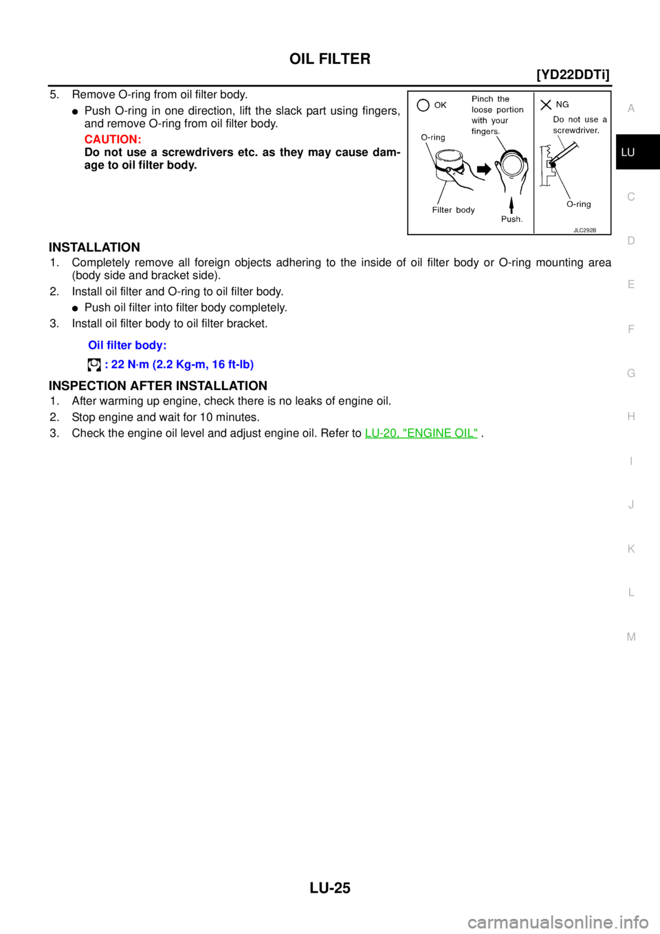
5. Remove O-ring from oil filter body.
�Push O-ring in one direction, lift the slack part using fingers,
and remove O-ring from oil filter body.
CAUTION:
Do not use a screwdrivers etc. as they may cause dam-
age to oil filter body.
INSTALLATION
1. Completely remove all foreign objects adhering to the inside of oil filter body or O-ring mounting area
(body side and bracket side).
2. Install oil filter and O-ring to oil filter body.
�Push oil filter into filter body completely.
3. Install oil filter body to oil filter bracket.
INSPECTION AFTER INSTALLATION
1. After warming up engine, check there is no leaks of engine oil.
2. Stop engine and wait for 10 minutes.
3. Check the engine oil level and adjust engine oil. Refer to LU-20, "
ENGINE OIL" .
JLC292B
Oil filter body:
: 22 N·m (2.2 Kg-m, 16 ft-lb)
Page 348 of 4555
LU-26
[YD22DDTi]
OIL FILTER BRACKET
OIL FILTER BRACKETPFP:15238
Removal and Installation (TYPE A)EBS00BL8
REMOVAL
CAUTION:
Be careful not to get burned when engine is hot.
1. Remove RH engine undercover.
2. Remove oil filter. Refer to LU-23, "
Removal and Installation (TYPE A)" .
3. Remove oil filter bracket.
INSTALLATION
Install all removed parts in the reverse order of removal.
�Insert the top mounting bolt to oil filter bracket beforehand, and set oil filter bracket to the installation loca-
tion.
INSPECTION AFTER INSTALLATION
1. After warming up engine, check there is no leaks of engine oil.
2. Stop engine and wait for 10 minutes.
3. Check the engine oil level and adjust engine oil. Refer to LU-20, "
ENGINE OIL" .
1. Oil pump housing 2. Gasket 3. Oil filter bracket
4. Oil filter
PBIC2380E
Page 349 of 4555
OIL FILTER BRACKET
LU-27
[YD22DDTi]
C
D
E
F
G
H
I
J
K
L
MA
LU
Removal and Installation (TYPE B)EBS011WJ
REMOVAL
CAUTION:
Be careful not to get burned when engine is hot.
1. Remove RH engine undercover.
2. Remove oil filter. Refer to LU-24, "
Removal and Installation (TYPE B)" .
3. Remove oil filter bracket.
INSTALLATION
Install all removed parts in the reverse order of removal.
�Insert the top mounting bolt to oil filter bracket beforehand, and set oil filter bracket to the installation loca-
tion.
INSPECTION AFTER INSTALLATION
1. After warming up engine, check there is no leaks of engine oil.
2. Stop engine and wait for 10 minutes.
3. Check the engine oil level and adjust engine oil. Refer to LU-20, "
ENGINE OIL" .
1. Oil pump housing 2. Gasket 3. Oil filler bracket
4. Oil filler 5. O-ring 6. Oil filter body
PBIC2537E
Page 350 of 4555
![NISSAN X-TRAIL 2005 Service Repair Manual LU-28
[YD22DDTi]
OIL COOLER
OIL COOLERPFP:21305
Removal and InstallationEBS00OE8
CAUTION:
�Be careful not to get burned when engine and engine oil are hot.
�When removing, prepare a shop cloth to ab](/manual-img/5/57403/w960_57403-349.png "NISSAN X-TRAIL 2005 Service Repair Manual LU-28
[YD22DDTi]
OIL COOLER
OIL COOLERPFP:21305
Removal and InstallationEBS00OE8
CAUTION:
�Be careful not to get burned when engine and engine oil are hot.
�When removing, prepare a shop cloth to ab")
LU-28
[YD22DDTi]
OIL COOLER
OIL COOLERPFP:21305
Removal and InstallationEBS00OE8
CAUTION:
�Be careful not to get burned when engine and engine oil are hot.
�When removing, prepare a shop cloth to absorb any engine oil leakage or spillage.
�Completely wipe off any engine oil that adhere to engine and vehicle.
REMOVAL
1. Remove engine undercover.
2. Drain engine coolant by removing cylinder block drain plug and radiator drain plug. Refer to CO-32,
"DRAINING ENGINE COOLANT" and EM-230, "CYLINDER BLOCK" .
3. Remove exhaust front tube. Refer to EX-2, "
EXHAUST SYSTEM" .
4. Remove water hoses.
5. Loosen connecting bolt and remove oil cooler.
INSPECTION AFTER REMOVAL
Check oil cooler for cracks. Check oil cooler for clogging by blowing through coolant inlet. If necessary, replace
oil cooler.
INSTALLATION
Installation is the reverse order of removal.
�Confirm that no foreign objects are adhering to the installation
planes of oil cooler or cylinder block.
�Tighten the connecting bolt after aligning the stopper on the cyl-
inder block side with protrusion of oil cooler.
INSPECTION AFTER INSTALLATION
1. Check the engine oil level and the engine coolant level, and adjust engine oil and engine coolant. Refer to
LU-20, "
ENGINE OIL" and CO-32, "ENGINE COOLANT" .
1. Oil cooler 2. O-ring 3. Water hose
4. Gasket 5. Water hose connector 6. Connecting bolt
PBIC2441E
SBIA0126E
Page 351 of 4555
OIL COOLER
LU-29
[YD22DDTi]
C
D
E
F
G
H
I
J
K
L
MA
LU
2. Start engine, and make sure that there is no leaks of engine oil or engine coolant.
3. Stop engine and wait for 10 minutes.
4. Check the engine oil level and the engine coolant level again. Refer to LU-20, "
ENGINE OIL" and CO-32,
"ENGINE COOLANT" .
Page 352 of 4555
![NISSAN X-TRAIL 2005 Service Repair Manual LU-30
[YD22DDTi]
OIL PUMP
OIL PUMPPFP:15010
Removal and InstallationEBS01AJ3
REMOVAL
Remove oil pump assembly. Refer to EM-198, "PRIMARY TIMING CHAIN" .
INSTALLATION
Installation is the reverse orde](/manual-img/5/57403/w960_57403-351.png "NISSAN X-TRAIL 2005 Service Repair Manual LU-30
[YD22DDTi]
OIL PUMP
OIL PUMPPFP:15010
Removal and InstallationEBS01AJ3
REMOVAL
Remove oil pump assembly. Refer to EM-198, \"PRIMARY TIMING CHAIN\" .
INSTALLATION
Installation is the reverse orde")
LU-30
[YD22DDTi]
OIL PUMP
OIL PUMPPFP:15010
Removal and InstallationEBS01AJ3
REMOVAL
Remove oil pump assembly. Refer to EM-198, "PRIMARY TIMING CHAIN" .
INSTALLATION
Installation is the reverse order of removal.
INSPECTION AFTER INSTALLATION
1. After warming up engine, check there is no leaks of engine oil.
2. Stop engine and wait for 10 minutes.
3. Check the engine oil level and adjust engine oil. Refer to LU-20, "
ENGINE OIL" .
Disassembly and AssemblyEBS01AI7
DISASSEMBLY
1. Remove oil pump cover.
2. Remove inner rotor and outer rotor from oil pump housing.
3. After removing regulator plug, remove inner and outer regulator springs and regulator valve.
INSPECTION AFTER DISASSEMBLY
Clearance of Oil Pump Parts
�Measure the clearance with feeler gauge.
Clearance between outer rotor and oil pump housing (position 1)
Tip clearance between inner rotor and outer rotor (position 2)
1. Oil pump housing 2. Outer rotor 3. Inner rotor
4. Oil pump cover 5. Regulator valve 6. Outer regulator spring
7. Inner regulator spring 8. Regulator plug
PBIC2381E
Standard : 0.114 - 0.260 mm (0.0045 - 0.0102 in)
Standard : Below 0.18 mm (0.0071in)
JLC355B
Page 369 of 4555
![NISSAN X-TRAIL 2005 Service Repair Manual RADIATOR
CO-13
[QR]
C
D
E
F
G
H
I
J
K
L
MA
CO
INSTALLATION
Installation is the reverse order of removal.
INSPECTION AFTER INSTALLATION
�Check for leaks of engine coolant using a radiator cap tester](/manual-img/5/57403/w960_57403-368.png "NISSAN X-TRAIL 2005 Service Repair Manual RADIATOR
CO-13
[QR]
C
D
E
F
G
H
I
J
K
L
MA
CO
INSTALLATION
Installation is the reverse order of removal.
INSPECTION AFTER INSTALLATION
�Check for leaks of engine coolant using a radiator cap tester")
RADIATOR
CO-13
[QR]
C
D
E
F
G
H
I
J
K
L
MA
CO
INSTALLATION
Installation is the reverse order of removal.
INSPECTION AFTER INSTALLATION
�Check for leaks of engine coolant using a radiator cap tester adapter (special service tool: EG17650301)
and a radiator cap tester (commercial service tool). Refer to CO-9, "
LEAK CHECK" .
�Start and warm up engine. Visually check if there is no leaks of engine coolant and A/T fluid (A/T models).
Checking Radiator CapEBS00KOK
�Check valve seat of radiator cap.
–Check if valve seat is swollen to the extent that the edge of the
plunger cannot be seen when watching it vertically from the top.
–Check if valve seat has no soil and damage.
�Pull negative-pressure valve to open it, and make sure that it is
completely closed when released.
–Make sure that there is no dirt or damage on the valve seat of
radiator cap negative-pressure valve.
–Make sure that there are no unusualness in the opening and
closing conditions of negative-pressure valve.
�Check radiator cap relief pressure.
–When connecting radiator cap to the radiator cap tester (com-
mercial service tool) and the radiator cap tester adapter [SST],
apply engine coolant to the cap seal surface.
�Replace radiator cap if there is an unusualness related to the above three.
CAUTION:
When installing radiator cap, thoroughly wipe out the radiator filler neck to remove any waxy residue
or foreign material.
Checking RadiatorEBS00KOL
Check radiator for mud or clogging. If necessary, clean radiator as follows.
�Be careful not to bend or damage radiator fins.
�When radiator is cleaned without removal, remove all surrounding parts such as cooling fan, radiator
shroud and horns. Then tape harness and connectors to prevent water from entering.
1. Apply water by hose to the back side of the radiator core vertically downward.
2. Apply water again to all radiator core surface once per minute.
PBIC2816E
SMA967B
Standard:
78 - 98 kPa (0.78 - 0.98bar, 0.8 - 1.0 kg/cm
2 , 11 - 14 psi)
Limit:
59 kPa (0.59bar, 0.6 kg/cm
2 , 9 psi)
SLC755AC
Page 392 of 4555
![NISSAN X-TRAIL 2005 Service Repair Manual CO-36
[YD22DDTi]
RADIATOR
�Start and warm up engine. Visually check if there is no leaks of engine coolant.
Checking Radiator CapEBS01FA3
�Check valve seat of radiator cap.
–Check if valve seat i](/manual-img/5/57403/w960_57403-391.png "NISSAN X-TRAIL 2005 Service Repair Manual CO-36
[YD22DDTi]
RADIATOR
�Start and warm up engine. Visually check if there is no leaks of engine coolant.
Checking Radiator CapEBS01FA3
�Check valve seat of radiator cap.
–Check if valve seat i")
CO-36
[YD22DDTi]
RADIATOR
�Start and warm up engine. Visually check if there is no leaks of engine coolant.
Checking Radiator CapEBS01FA3
�Check valve seat of radiator cap.
–Check if valve seat is swollen to the extent that the edge of the
plunger cannot be seen when watching it vertically from the top.
–Check if valve seat has no soil and damage.
�Pull negative-pressure valve to open it, and make sure that it is
completely closed when released.
–Make sure that there is no dirt or damage on the valve seat of
radiator cap negative-pressure valve.
–Make sure that there are no unusualness in the opening and
closing conditions of negative-pressure valve.
�Check radiator cap relief pressure.
–When connecting radiator cap to the radiator cap tester (com-
mercial service tool) and the radiator cap tester adapter (special
service tool), apply engine coolant to the cap seal surface.
�Replace radiator cap if there is an unusualness related to the above three.
CAUTION:
When installing radiator cap, thoroughly wipe out the radiator filler neck to remove any waxy residue
or foreign material.
Checking RadiatorEBS011WN
Check radiator for mud or clogging. If necessary, clean radiator as follows.
�Be careful not to bend or damage the radiator fins.
�When radiator is cleaned without removal, remove all surrounding parts such as cooling fan, radiator
shroud and horns. Then tape the harness and connectors to prevent water from entering.
1. Apply water by hose to the back side of the radiator core vertically downwards.
2. Apply water again to all radiator core surface once per minute.
3. Stop washing if any stains no longer flow out from the radiator.
4. Blow air into the back side of radiator core vertically downwards.
�Use compressed air lower than 490 kPa (4.9 bar, 5 kg/cm2 , 71psi) and keep distance more than 30 cm
(11.8 in).
5. Blow air again into all the radiator core surface once per minute until no water sprays out.
PBIC2816E
SMA967B
Standard:
78 - 98 kPa (0.78 - 0.98bar, 0.8 - 1.0 kg/cm
2 , 11 - 14 psi)
Limit:
59 kPa (0.59bar, 0.6 kg/cm
2 , 9 psi)
SLC755AC
![NISSAN X-TRAIL 2005 Service Repair Manual LU-26
[YD22DDTi]
OIL FILTER BRACKET
OIL FILTER BRACKETPFP:15238
Removal and Installation (TYPE A)EBS00BL8
REMOVAL
CAUTION:
Be careful not to get burned when engine is hot.
1. Remove RH engine under](/manual-img/5/57403/w960_57403-347.png "NISSAN X-TRAIL 2005 Service Repair Manual LU-26
[YD22DDTi]
OIL FILTER BRACKET
OIL FILTER BRACKETPFP:15238
Removal and Installation (TYPE A)EBS00BL8
REMOVAL
CAUTION:
Be careful not to get burned when engine is hot.
1. Remove RH engine under")
![NISSAN X-TRAIL 2005 Service Repair Manual OIL FILTER BRACKET
LU-27
[YD22DDTi]
C
D
E
F
G
H
I
J
K
L
MA
LU
Removal and Installation (TYPE B)EBS011WJ
REMOVAL
CAUTION:
Be careful not to get burned when engine is hot.
1. Remove RH engine underco](/manual-img/5/57403/w960_57403-348.png "NISSAN X-TRAIL 2005 Service Repair Manual OIL FILTER BRACKET
LU-27
[YD22DDTi]
C
D
E
F
G
H
I
J
K
L
MA
LU
Removal and Installation (TYPE B)EBS011WJ
REMOVAL
CAUTION:
Be careful not to get burned when engine is hot.
1. Remove RH engine underco")
![NISSAN X-TRAIL 2005 Service Repair Manual OIL COOLER
LU-29
[YD22DDTi]
C
D
E
F
G
H
I
J
K
L
MA
LU
2. Start engine, and make sure that there is no leaks of engine oil or engine coolant.
3. Stop engine and wait for 10 minutes.
4. Check the engi](/manual-img/5/57403/w960_57403-350.png "NISSAN X-TRAIL 2005 Service Repair Manual OIL COOLER
LU-29
[YD22DDTi]
C
D
E
F
G
H
I
J
K
L
MA
LU
2. Start engine, and make sure that there is no leaks of engine oil or engine coolant.
3. Stop engine and wait for 10 minutes.
4. Check the engi")