2005 NISSAN NAVARA radiator core support
[x] Cancel search: radiator core supportPage 252 of 3171
AT-244
A/T FLUID COOLER
A/T FLUID COOLER
PFP:21600
Removal and InstallationECS00G56
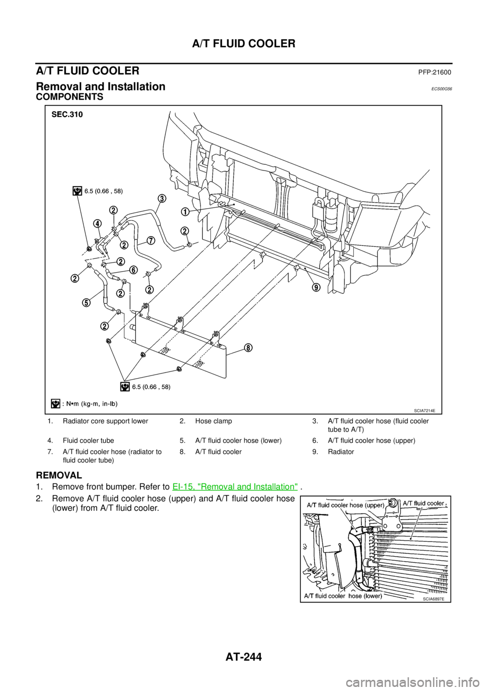
COMPONENTS
REMOVAL
1. Remove front bumper. Refer toEI-15, "Removal and Installation".
2. Remove A/T fluid cooler hose (upper) and A/T fluid cooler hose
(lower) from A/T fluid cooler.
1. Radiator core support lower 2. Hose clamp 3. A/T fluid cooler hose (fluid cooler
tube to A/T)
4. Fluid cooler tube 5. A/T fluid cooler hose (lower) 6. A/T fluid cooler hose (upper)
7. A/T fluid cooler hose (radiator to
fluid cooler tube)8. A/T fluid cooler 9. Radiator
SCIA7214E
SCIA6897E
Page 253 of 3171
A/T FLUID COOLER
AT-245
D
E
F
G
H
I
J
K
L
MA
B
AT
3. Pull A/T fluid cooler (1) toward the front of the vehicle to release
from radiator core support lower (2), and then slide A/T fluid
cooler (1) downward to remove radiator (3).
INSTALLATION
CAUTION:
After completing installation, check for A/T fluid leakage and fluid level. Refer toAT-12, "
Checking A/T
Fluid".
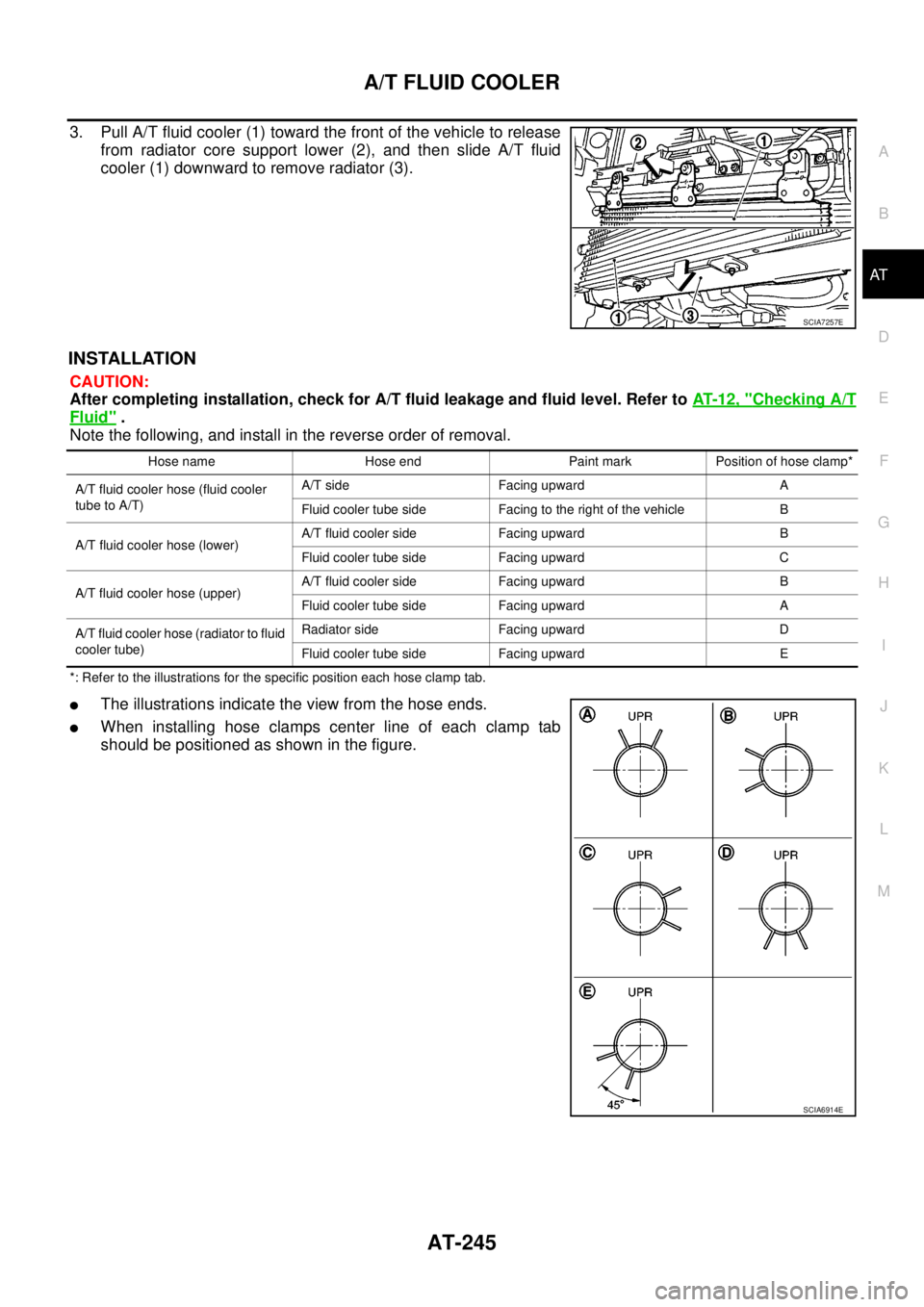
Note the following, and install in the reverse order of removal.
*: Refer to the illustrations for the specific position each hose clamp tab.
lThe illustrations indicate the view from the hose ends.
lWhen installing hose clamps center line of each clamp tab
should be positioned as shown in the figure.
SCIA7257E
Hose name Hose end Paint mark Position of hose clamp*
A/T fluid cooler hose (fluid cooler
tube to A/T)A/T side Facing upward A
Fluid cooler tube side Facing to the right of the vehicle B
A/T fluid cooler hose (lower)A/T fluid cooler side Facing upward B
Fluid cooler tube side Facing upward C
A/T fluid cooler hose (upper)A/T fluid cooler side Facing upward B
Fluid cooler tube side Facing upward A
A/T fluid cooler hose (radiator to fluid
cooler tube)Radiator side Facing upward D
Fluid cooler tube side Facing upward E
SCIA6914E
Page 439 of 3171
TROUBLE DIAGNOSIS
ATC-105
C
D
E
F
G
H
I
K
L
MA
B
AT C
Ambient Sensor CircuitEJS006BW
COMPONENT DESCRIPTION
Ambient Sensor
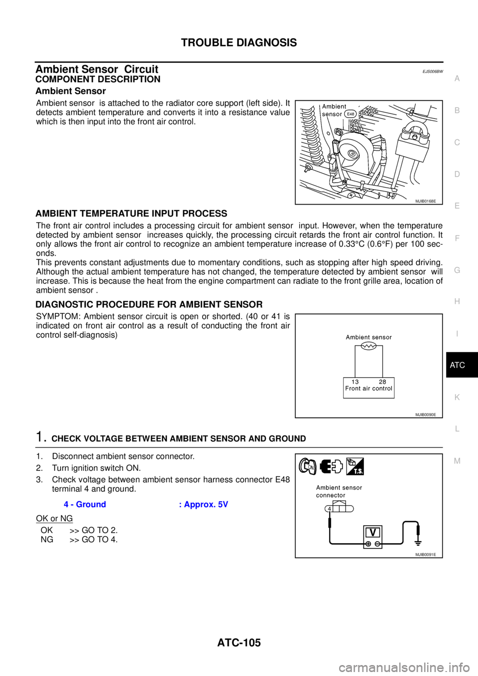
Ambient sensor is attached to the radiator core support (left side). It
detects ambient temperature and converts it into a resistance value
which is then input into the front air control.
AMBIENT TEMPERATURE INPUT PROCESS
The front air control includes a processing circuit for ambient sensor input. However, when the temperature
detected by ambient sensor increases quickly, the processing circuit retards the front air control function. It
only allows the front air control to recognize an ambient temperature increase of 0.33°C(0.6°F) per 100 sec-
onds.
This prevents constant adjustments due to momentary conditions, such as stopping after high speed driving.
Although the actual ambient temperature has not changed, the temperature detected by ambient sensor will
increase. This is because the heat from the engine compartment can radiate to the front grille area, location of
ambient sensor .
DIAGNOSTIC PROCEDURE FOR AMBIENT SENSOR
SYMPTOM: Ambient sensor circuit is open or shorted. (40 or 41 is
indicated on front air control as a result of conducting the front air
control self-diagnosis)
1.CHECK VOLTAGE BETWEEN AMBIENT SENSOR AND GROUND
1. Disconnect ambient sensor connector.
2. Turn ignition switch ON.
3. Check voltage between ambient sensor harness connector E48
terminal 4 and ground.
OK or NG
OK >> GO TO 2.
NG >> GO TO 4.
MJIB0168E
MJIB0090E
4 - Ground : Approx. 5V
MJIB0091E
Page 585 of 3171

BL-1
BODY, LOCK & SECURITY SYSTEM
IBODY
CONTENTS
C
D
E
F
G
H
J
K
L
M
SECTIONBL
A
B
BL
BODY, LOCK & SECURITY SYSTEM
PRECAUTIONS .......................................................... 4
Precautions for Supplemental Restraint System
(SRS)“AIRBAG”and“SEATBELTPRE-TEN-
SIONER” .................................................................. 4
Precautions for procedures with out cowl top cover..... 4
Precautions for Work ................................................ 4
Wiring Diagrams and Trouble Diagnosis .................. 4
PREPARATION ........................................................... 5
Commercial Service Tools ........................................ 5
SQUEAK AND RATTLE TROUBLE DIAGNOSES..... 6
Work Flow ................................................................ 6
CUSTOMER INTERVIEW ..................................... 6
DUPLICATE THE NOISE AND TEST DRIVE ....... 7
CHECK RELATED SERVICE BULLETINS ........... 7
LOCATE THE NOISE AND IDENTIFY THE
ROOT CAUSE ...................................................... 7
REPAIR THE CAUSE ........................................... 7
CONFIRM THE REPAIR ....................................... 8
Generic Squeak and Rattle Troubleshooting ........... 8
INSTRUMENT PANEL .......................................... 8
CENTER CONSOLE ............................................. 8
DOORS ................................................................. 8
TRUNK .................................................................. 9
SUNROOF/HEADLINING ..................................... 9
SEATS ................................................................... 9
UNDERHOOD ....................................................... 9
Diagnostic Worksheet ............................................ 10
HOOD ....................................................................... 12
Fitting Adjustment .................................................. 12
LONGITUDINAL AND LATERAL CLEARANCE
ADJUSTMENT .................................................... 13
FRONT END HEIGHT ADJUSTMENT ............... 13
SURFACE HEIGHT ADJUSTMENT ................... 13
Removal and Installation of Hood Assembly .......... 14
REMOVAL ........................................................... 14
INSTALLATION ................................................... 14
Removal and Installation of Hood Hinge ................ 15
REMOVAL ........................................................... 15
INSTALLATION ................................................... 15
Removal and Installation of Hood Lock Control ..... 15REMOVAL ........................................................... 15
INSTALLATION ................................................... 16
Hood Lock Control Inspection ................................ 17
RADIATOR CORE SUPPORT .................................. 18
Removal and Installation ........................................ 18
REMOVAL ........................................................... 18
INSTALLATION ................................................... 19
FRONT FENDER ...................................................... 20
Removal and Installation ........................................ 20
REMOVAL ........................................................... 20
INSTALLATION ................................................... 20
POWER DOOR LOCK SYSTEM .............................. 21
Component Parts and Harness Connector Location... 21
KING CAB ........................................................... 21
DOUBLE CAB ..................................................... 22
System Description ................................................. 23
OUTLINE ............................................................. 24
CAN Communication System Description .............. 25
CAN Communication Unit ....................................... 25
Schematic ............................................................... 26
Wiring Diagram —D/LOCK— ................................. 27
Terminals and Reference Value for BCM ............... 34
CONSULT-II Function (BCM) ................................. 35
CONSULT-II BASIC OPERATION PROCEDURE
... 35
CONSULT-II APPLICATION ITEMS .................... 36
Work Flow ............................................................... 37
Trouble Diagnoses Chart by Symptom ................... 37
Check Power Supply and Ground Circuit ............... 37
Check Door Switch ................................................. 39
CHECK DOOR SWITCH (DOUBLE CAB) .......... 39
CHECK DOOR SWITCH (KING CAB) ................ 41
Check Key Switch ................................................... 43
Check Door Key Cylinder Switch (LHD Model Only)... 45
Check Front Door Lock Actuator (Driver Side) ....... 48
Check Front Door Lock Actuator (Passenger Side)... 49
Check Front Door Lock Actuator Switch ................. 50
Check Rear Door Lock Actuator LH (Double Cab
Model) ..................................................................... 50
Check Rear Door Lock Actuator RH (Double Cab
Page 599 of 3171
HOOD
BL-15
C
D
E
F
G
H
J
K
L
MA
B
BL
Removal and Installation of Hood HingeEIS00C49
REMOVAL
1. Remove the hood assembly. Refer toBL-14, "Removal and
Installation of Hood Assembly".
2. Remove the front fender. Refer toBL-20, "
Removal and Installa-
tion".
3. Remove the hood hinge mounting bolts and remove the hood
hinge.
INSTALLATION
Install in the reverse order of removal.
CAUTION:
After installing, apply touch-up paint (the body color) onto the head of the hinge mounting nuts.
Removal and Installation of Hood Lock ControlEIS00B4K
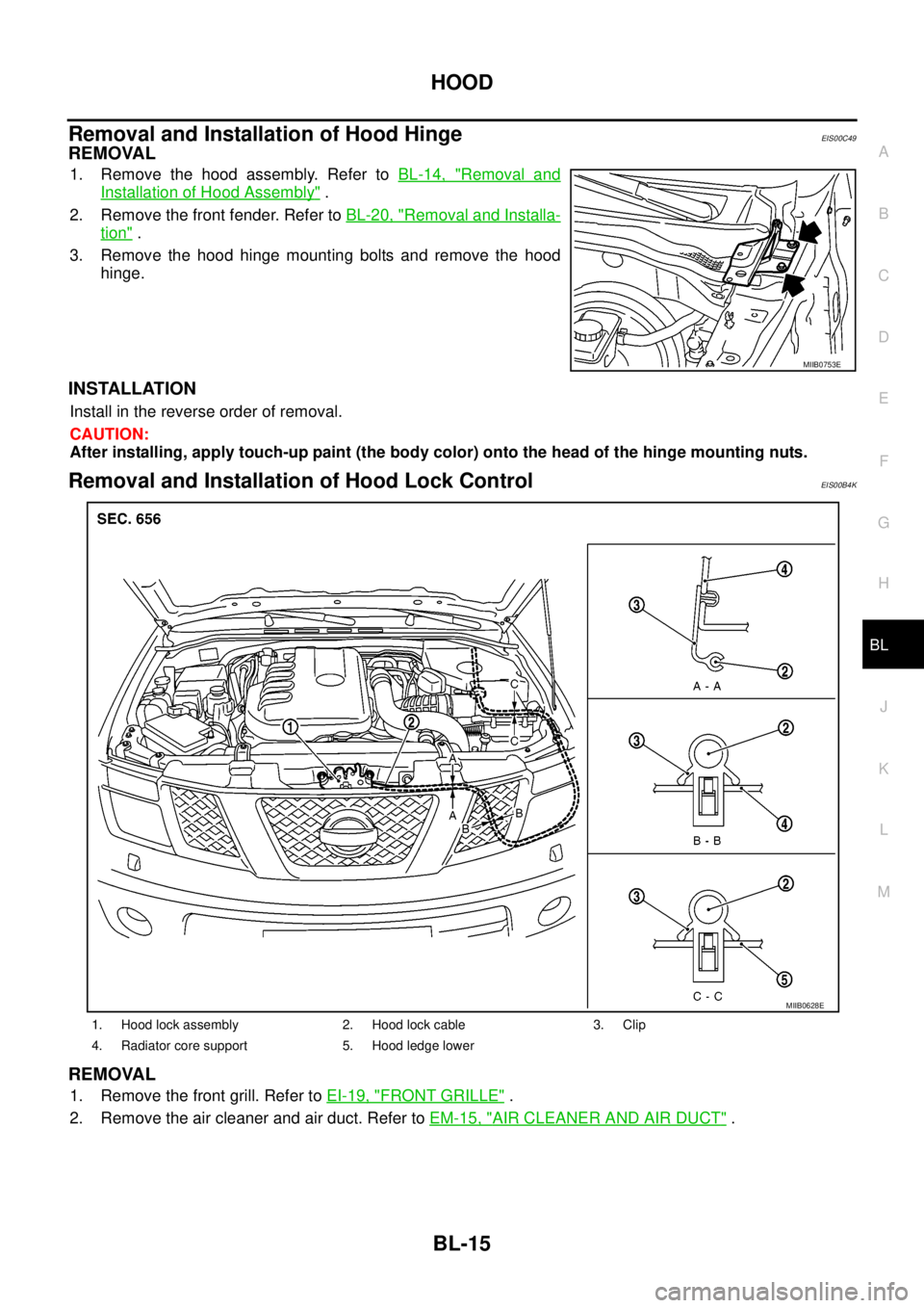
REMOVAL
1. Remove the front grill. Refer toEI-19, "FRONT GRILLE".
2. Remove the air cleaner and air duct. Refer toEM-15, "
AIR CLEANER AND AIR DUCT".
MIIB0753E
1. Hood lock assembly 2. Hood lock cable 3. Clip
4. Radiator core support 5. Hood ledge lower
MIIB0628E
Page 600 of 3171
BL-16
HOOD
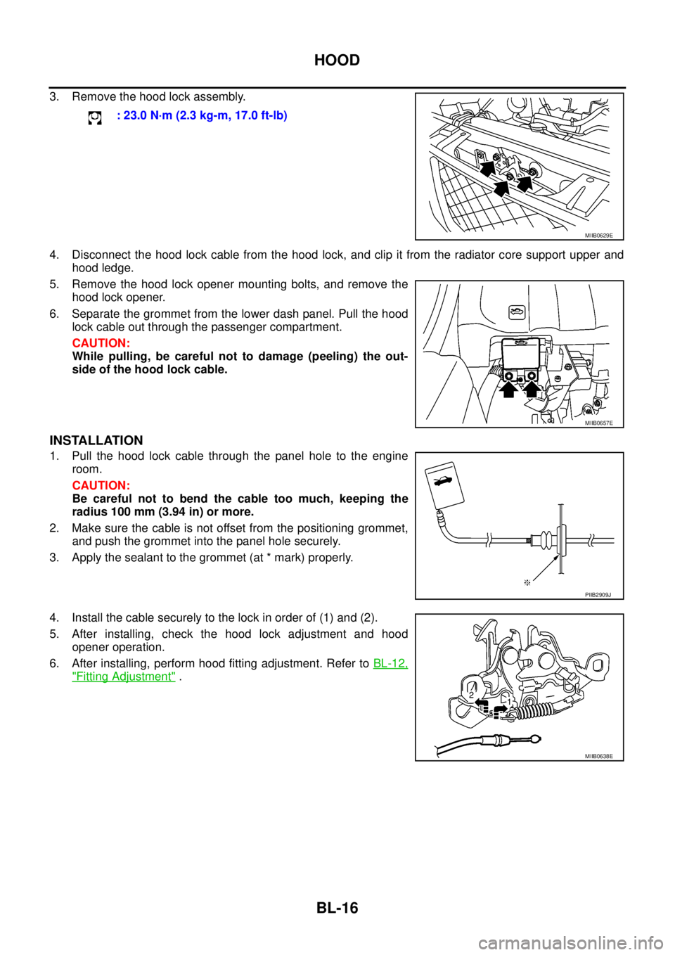
3. Remove the hood lock assembly.
4. Disconnect the hood lock cable from the hood lock, and clip it from the radiator core support upper and
hood ledge.
5. Remove the hood lock opener mounting bolts, and remove the
hood lock opener.
6. Separate the grommet from the lower dash panel. Pull the hood
lock cable out through the passenger compartment.
CAUTION:
While pulling, be careful not to damage (peeling) the out-
side of the hood lock cable.
INSTALLATION
1. Pull the hood lock cable through the panel hole to the engine
room.
CAUTION:
Be careful not to bend the cable too much, keeping the
radius 100 mm (3.94 in) or more.
2. Make sure the cable is not offset from the positioning grommet,
and push the grommet into the panel hole securely.
3. Apply the sealant to the grommet (at * mark) properly.
4. Install the cable securely to the lock in order of (1) and (2).
5. After installing, check the hood lock adjustment and hood
opener operation.
6. After installing, perform hood fitting adjustment. Refer toBL-12,
"Fitting Adjustment". : 23.0 N·m (2.3 kg-m, 17.0 ft-lb)
MIIB0629E
MIIB0657E
PIIB2909J
MIIB0638E
Page 602 of 3171

BL-18
RADIATOR CORE SUPPORT
RADIATOR CORE SUPPORT
PFP:62500
Removal and InstallationEIS00DGJ
REMOVAL
1. Remove the hood assembly. Refer toBL-14, "Removal and Installation of Hood Assembly".
2. Remove the front grille. Refer toEI-19, "
FRONT GRILLE".
3. Remove the front bumper, bumper reinforcement and bumper bracket. Refer toEI-15, "
FRONT BUMPER"
.
4. Remove the headlamp assembly (LH/RH). Refer toLT-30, "
Removal and Installation".
5. Remove the air intake duct (Air guide). Refer toEM-15, "
AIR CLEANER AND AIR DUCT".
6. Remove the charge air cooler. (for YD25 engine models only) Refer toEM-18, "
CHARGE AIR COOLER".
7. Remove the power steering oil cooler. Refer toPS-30, "
HYDRAULIC LINE".
8. Remove the A/T fluid cooler and A/T fluid cooler tube mounting nuts. Refer toAT- 2 4 4 , "
A/T FLUID
COOLER".
9. Remove the hood lock assembly, and then remove the hood lock cable. Refer toBL-15, "
Removal and
Installation of Hood Lock Control".
10. Remove the horn harness connector.
11. Disconnect the ambient sensor connector and remove the ambient sensor. Refer toAT C - 11 7 , "
Removal
and Installation".
12. Remove the mounting harness clip on radiator core support assembly, the harness is separate.
13. Remove the upper radiator bracket. Refer toCO-11, "
RADIATOR".
1. Radiator core support assembly 2. Air intake duct (Air guide) RH 3. Air intake duct (Air guide) LH
4. Horn (Low) 5. Headlamp lower bracket RH 6. Headlamp lower bracket LH
7. Headlamp side bracket RH 8. Headlamp side bracket LH
MIIB0979E
Page 603 of 3171

RADIATOR CORE SUPPORT
BL-19
C
D
E
F
G
H
J
K
L
MA
B
BL
14. Remove the radiator core support mounting bolts and remove the radiator core support assembly.
15. After removing the radiator core support assembly, the following parts are separate.
lHorn (Low).
lHeadlamp side bracket (LH/RH).
lHeadlamp lower bracket (LH/RH).
INSTALLATION
Install in the reverse order of removal.
CAUTION:
After installing, check the hood adjustment and hood opener operation. Refer toBL-12, "
Fitting
Adjustment"andBL-17, "Hood Lock Control Inspection".