Page 2280 of 3171
DESCRIPTION
MA-5
C
D
E
F
G
H
I
J
K
MA
B
MA
DESCRIPTIONPFP:00000
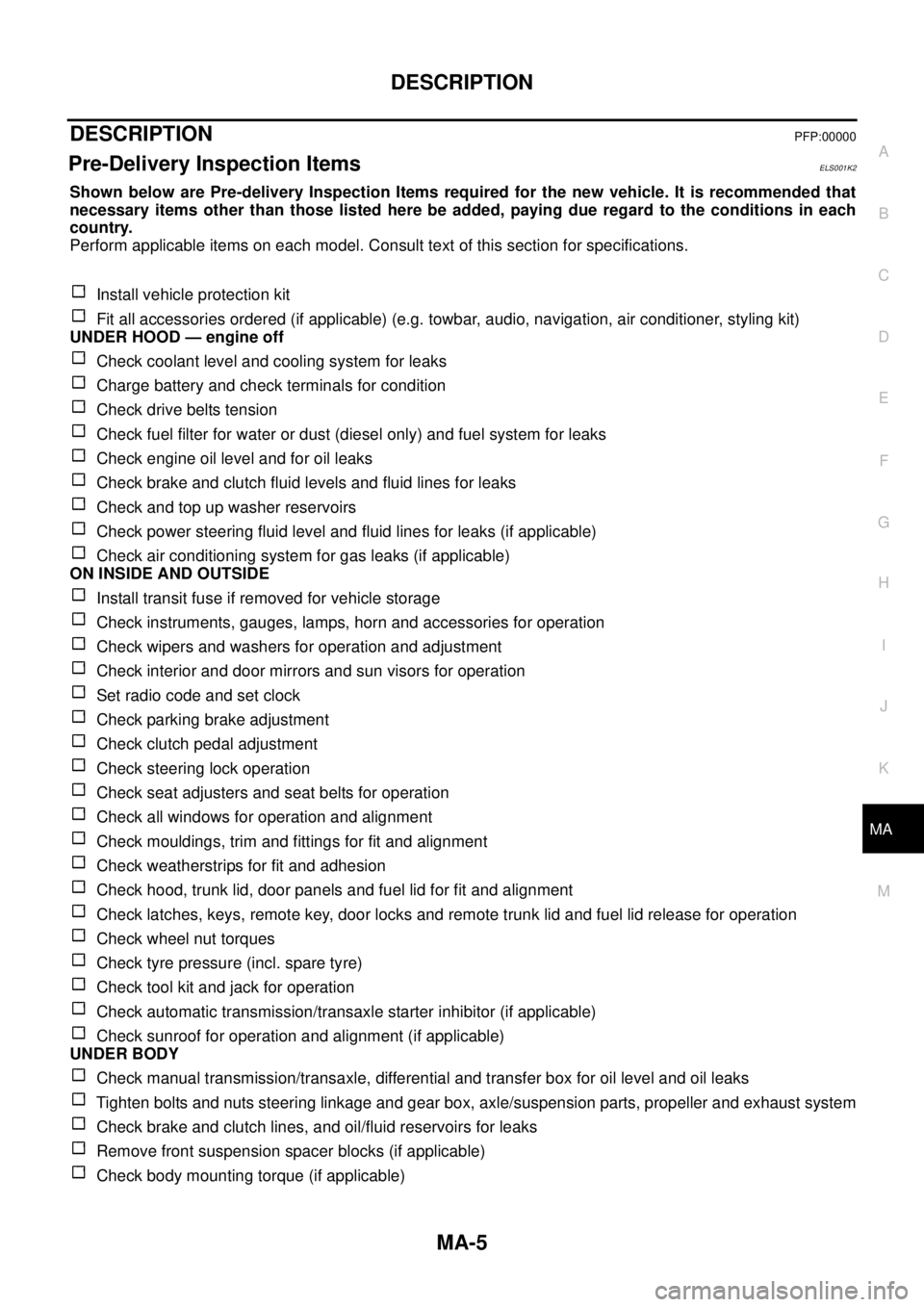
Pre-Delivery Inspection ItemsELS001K2
Shown below are Pre-delivery Inspection Items required for the new vehicle. It is recommended that
necessary items other than those listed here be added, paying due regard to the conditions in each
country.
Perform applicable items on each model. Consult text of this section for specifications.
Install vehicle protection kit
Fit all accessories ordered (if applicable) (e.g. towbar, audio, navigation, air conditioner, styling kit)
UNDER HOOD — engine off
Check coolant level and cooling system for leaks
Charge battery and check terminals for condition
Check drive belts tension
Check fuel filter for water or dust (diesel only) and fuel system for leaks
Check engine oil level and for oil leaks
Check brake and clutch fluid levels and fluid lines for leaks
Check and top up washer reservoirs
Check power steering fluid level and fluid lines for leaks (if applicable)
Check air conditioning system for gas leaks (if applicable)
ON INSIDE AND OUTSIDE
Install transit fuse if removed for vehicle storage
Check instruments, gauges, lamps, horn and accessories for operation
Check wipers and washers for operation and adjustment
Check interior and door mirrors and sun visors for operation
Set radio code and set clock
Check parking brake adjustment
Check clutch pedal adjustment
Check steering lock operation
Check seat adjusters and seat belts for operation
Check all windows for operation and alignment
Check mouldings, trim and fittings for fit and alignment
Check weatherstrips for fit and adhesion
Check hood, trunk lid, door panels and fuel lid for fit and alignment
Check latches, keys, remote key, door locks and remote trunk lid and fuel lid release for operation
Check wheel nut torques
Check tyre pressure (incl. spare tyre)
Check tool kit and jack for operation
Check automatic transmission/transaxle starter inhibitor (if applicable)
Check sunroof for operation and alignment (if applicable)
UNDER BODY
Check manual transmission/transaxle, differential and transfer box for oil level and oil leaks
Tighten bolts and nuts steering linkage and gear box, axle/suspension parts, propeller and exhaust system
Check brake and clutch lines, and oil/fluid reservoirs for leaks
Remove front suspension spacer blocks (if applicable)
Check body mounting torque (if applicable)
Page 2486 of 3171
INTAKE SENSOR
MTC-99
C
D
E
F
G
H
I
K
L
MA
B
MTC
INTAKE SENSORPFP:27723
Removal and InstallationEJS005GT
REMOVAL
1. Remove the instrument panel. Refer toIP-10, "Removal and Installation".
2. Disconnect the intake sensor electrical connector.
NOTE:
The intake sensor is located on the top of the heater and cooling
unit assembly next to the A/C evaporator cover.
3. Twist the intake sensor to remove the intake sensor from the
heater and cooling unit assembly.
INSTALLATION
Installation is in the reverse order of removal.
MJIB0325E
Page 2487 of 3171
MTC-100
BLOWER MOTOR
BLOWER MOTOR
PFP:27226
ComponentsEJS005GU
Removal and InstallationEJS005GV
REMOVAL
1. Remove the glove box assembly. Refer toIP-15, "LOWER INSTRUMENT PANEL RH AND GLOVE BOX"
.
2. Disconnect the blower motor electrical connector.
3. Remove the three screws and remove the blower motor.
INSTALLATION
Installation is in the reverse order of removal.
1. Heater and cooling unit assembly 2. Blower motor 3. Blower motor resistor
MJIB0247E
Page 2488 of 3171
AIR CONDITIONER FILTER
MTC-101
C
D
E
F
G
H
I
K
L
MA
B
MTC
AIR CONDITIONER FILTERPFP:27277
Removal and InstallationEJS005GW
FUNCTION
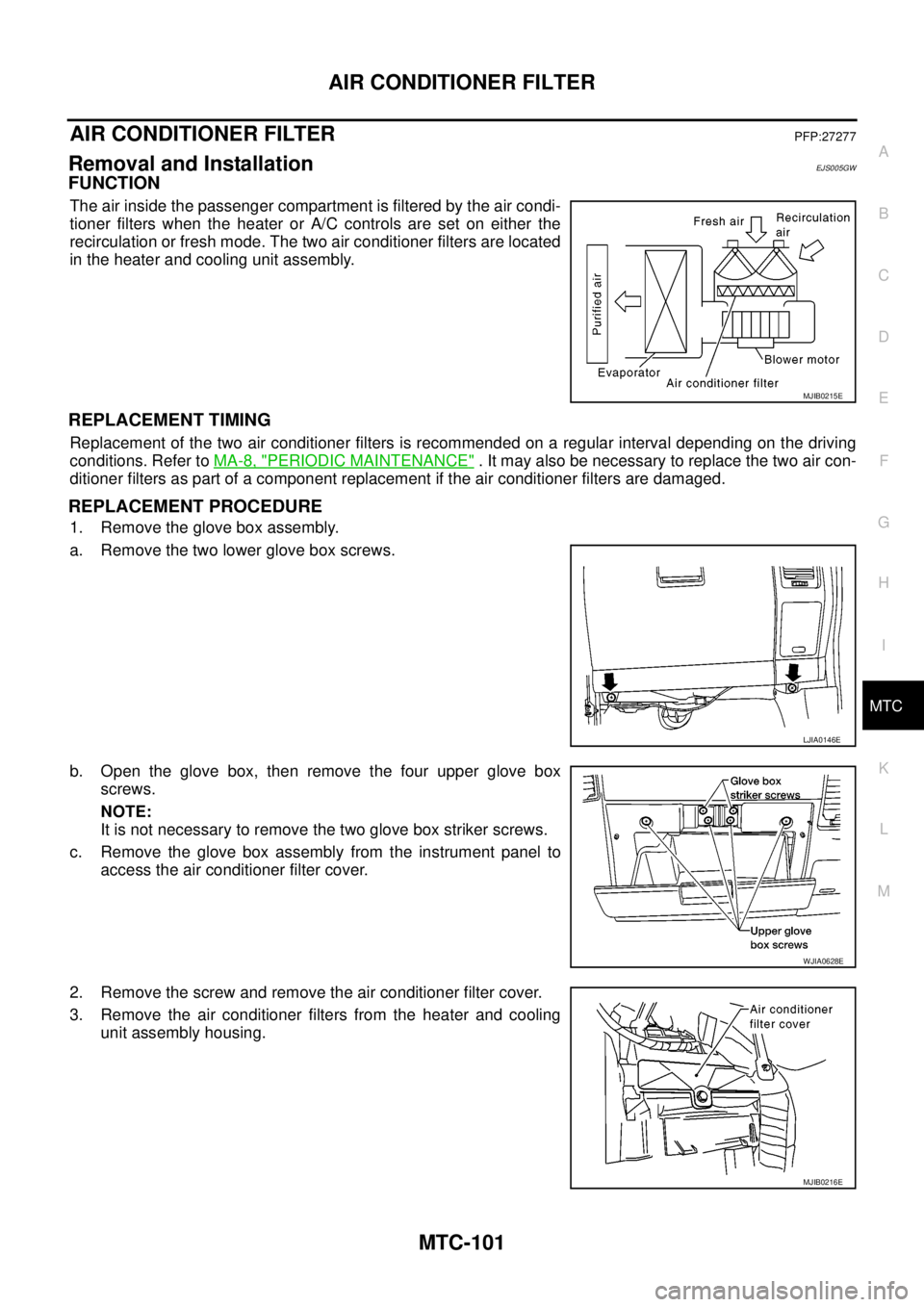
The air inside the passenger compartment is filtered by the air condi-
tioner filters when the heater or A/C controls are set on either the
recirculation or fresh mode. The two air conditioner filters are located
in the heater and cooling unit assembly.
REPLACEMENT TIMING
Replacement of the two air conditioner filters is recommended on a regular interval depending on the driving
conditions. Refer toMA-8, "
PERIODIC MAINTENANCE". It may also be necessary to replace the two air con-
ditioner filters as part of a component replacement if the air conditioner filters are damaged.
REPLACEMENT PROCEDURE
1. Remove the glove box assembly.
a. Remove the two lower glove box screws.
b. Open the glove box, then remove the four upper glove box
screws.
NOTE:
It is not necessary to remove the two glove box striker screws.
c. Remove the glove box assembly from the instrument panel to
access the air conditioner filter cover.
2. Remove the screw and remove the air conditioner filter cover.
3. Remove the air conditioner filters from the heater and cooling
unit assembly housing.
MJIB0215E
LJIA0146E
WJIA0628E
MJIB0216E
Page 2492 of 3171
HEATER & COOLING UNIT ASSEMBLY
MTC-105
C
D
E
F
G
H
I
K
L
MA
B
MTC
Removal and InstallationEJS005GY
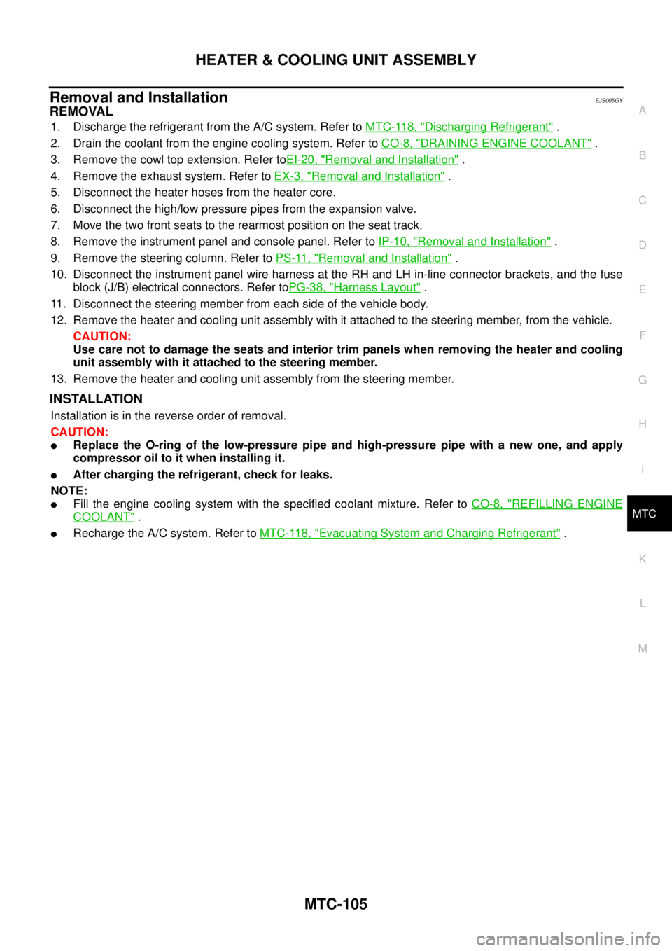
REMOVAL
1. Discharge the refrigerant from the A/C system. Refer toMTC-118, "Discharging Refrigerant".
2. Drain the coolant from the engine cooling system. Refer toCO-8, "
DRAINING ENGINE COOLANT".
3. Remove the cowl top extension. Refer toEI-20, "
Removal and Installation".
4. Remove the exhaust system. Refer toEX-3, "
Removal and Installation".
5. Disconnect the heater hoses from the heater core.
6. Disconnect the high/low pressure pipes from the expansion valve.
7. Move the two front seats to the rearmost position on the seat track.
8. Remove the instrument panel and console panel. Refer toIP-10, "
Removal and Installation".
9. Remove the steering column. Refer toPS-11, "
Removal and Installation".
10. Disconnect the instrument panel wire harness at the RH and LH in-line connector brackets, and the fuse
block (J/B) electrical connectors. Refer toPG-38, "
Harness Layout".
11. Disconnect the steering member from each side of the vehicle body.
12. Remove the heater and cooling unit assembly with it attached to the steering member, from the vehicle.
CAUTION:
Use care not to damage the seats and interior trim panels when removing the heater and cooling
unit assembly with it attached to the steering member.
13. Remove the heater and cooling unit assembly from the steering member.
INSTALLATION
Installation is in the reverse order of removal.
CAUTION:
lReplace the O-ring of the low-pressure pipe and high-pressure pipe with a new one, and apply
compressor oil to it when installing it.
lAfter charging the refrigerant, check for leaks.
NOTE:
lFill the engine cooling system with the specified coolant mixture. Refer toCO-8, "REFILLING ENGINE
COOLANT".
lRecharge the A/C system. Refer toMTC-118, "Evacuating System and Charging Refrigerant".
Page 2502 of 3171
DUCTS AND GRILLES
MTC-115
C
D
E
F
G
H
I
K
L
MA
B
MTC
Grilles
MJIB0251E
1. Overhead console trim panel 2. Overhead console front grilles (front) 3. Overhead console rear grilles (rear)
4. Instrument panel 5. Storage tray bottom cover (LH) 6. LH side ventilator and demister grille
Page 2503 of 3171
MTC-116
DUCTS AND GRILLES
Removal and Installation
EJS005H9
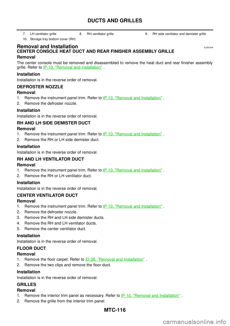
CENTER CONSOLE HEAT DUCT AND REAR FINISHER ASSEMBLY GRILLE
Removal
The center console must be removed and disassembled to remove the heat duct and rear finisher assembly
grille. Refer toIP-10, "
Removal and Installation".
Installation
Installation is in the reverse order of removal.
DEFROSTER NOZZLE
Removal
1. Remove the instrument panel trim. Refer toIP-10, "Removal and Installation".
2. Remove the defroster nozzle.
Installation
Installation is in the reverse order of removal.
RH AND LH SIDE DEMISTER DUCT
Removal
1. Remove the instrument panel trim. Refer toIP-10, "Removal and Installation".
2. Remove the RH or LH side demister duct.
Installation
Installation is in the reverse order of removal.
RH AND LH VENTILATOR DUCT
Removal
1. Remove the instrument panel trim. Refer toIP-10, "Removal and Installation".
2. Remove the RH or LH ventilator duct.
Installation
Installation is in the reverse order of removal.
CENTER VENTILATOR DUCT
Removal
1. Remove the instrument panel trim. Refer toIP-10, "Removal and Installation".
2. Remove the defroster nozzle.
3. Remove the RH and LH side demister ducts.
4. Remove the RH and LH ventilator ducts.
5. Remove the center ventilator duct.
Installation
Installation is in the reverse order of removal.
FLOOR DUCT
Removal
1. Remove the floor carpet. Refer toEI-38, "Removal and Installation".
2. Remove the two clips and remove the floor duct.
Installation
Installation is in the reverse order of removal.
GRILLES
Removal
1. Remove the interior trim panel as necessary. Refer toIP-10, "Removal and Installation".
2. Remove the grille from the interior trim panel.
7. LH ventilator grille 8. RH ventilator grille 9. RH side ventilator and demister grille
10. Storage tray bottom cover (RH)
Page 2638 of 3171
STEERING COLUMN
PS-11
C
D
E
F
H
I
J
K
L
MA
B
PS
STEERING COLUMNPFP:48810
Removal and InstallationEGS001LI
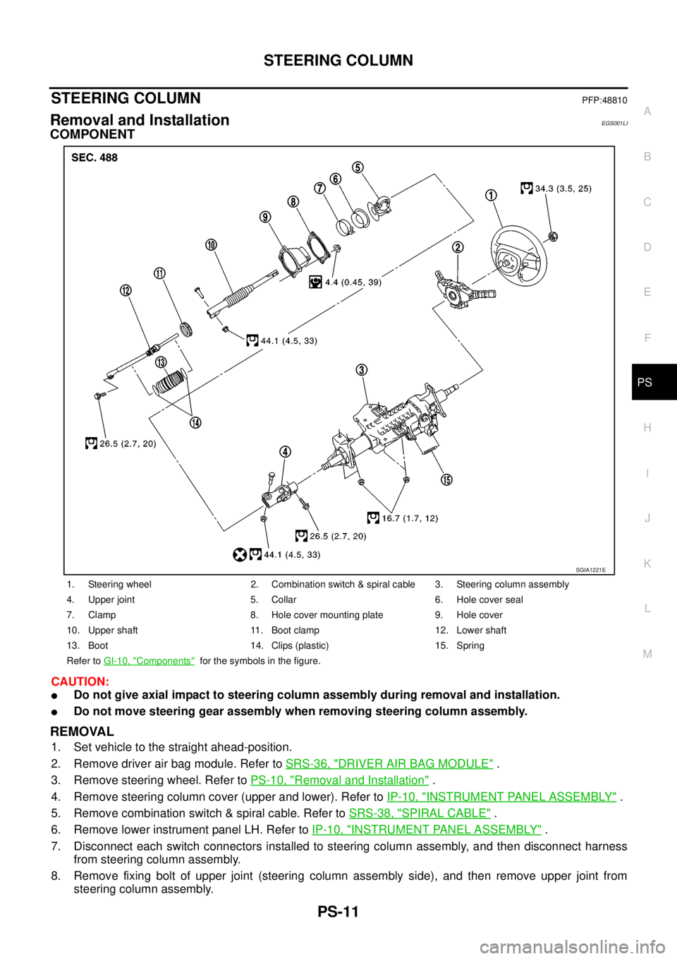
COMPONENT
CAUTION:
lDo not give axial impact to steering column assembly during removal and installation.
lDo not move steering gear assembly when removing steering column assembly.
REMOVAL
1. Set vehicle to the straight ahead-position.
2. Remove driver air bag module. Refer toSRS-36, "
DRIVER AIR BAG MODULE".
3. Remove steering wheel. Refer toPS-10, "
Removal and Installation".
4. Remove steering column cover (upper and lower). Refer toIP-10, "
INSTRUMENT PANEL ASSEMBLY".
5. Remove combination switch & spiral cable. Refer toSRS-38, "
SPIRAL CABLE".
6. Remove lower instrument panel LH. Refer toIP-10, "
INSTRUMENT PANEL ASSEMBLY".
7. Disconnect each switch connectors installed to steering column assembly, and then disconnect harness
from steering column assembly.
8. Remove fixing bolt of upper joint (steering column assembly side), and then remove upper joint from
steering column assembly.
1. Steering wheel 2. Combination switch & spiral cable 3. Steering column assembly
4. Upper joint 5. Collar 6. Hole cover seal
7. Clamp 8. Hole cover mounting plate 9. Hole cover
10. Upper shaft 11. Boot clamp 12. Lower shaft
13. Boot 14. Clips (plastic) 15. Spring
Refer toGI-10, "
Components"for the symbols in the figure.
SGIA1221E