Page 1772 of 3171
INSTRUMENT PANEL ASSEMBLY
IP-13
C
D
E
F
G
H
J
K
L
MA
B
IP
LOWER INSTRUMENT PANEL LH
Removal
1. Remove LH front kick plate.
2. Remove lower dash side finisher. Refer toEI-34, "
Removal".
3. Remove front pillar finisher. Refer toEI-35, "
Removal".
4. Remove screws using power tool, and remove lower instrument
panel LH.
5. Pull rearward to release clips, disconnect connectors, and
remove lower instrument panel LH.
Installation
Installation is in the reverse order of removal.
COMBINATION METER
Removal
1. Disconnect the negative battery cable.
2. Remove the lower instrument panel LH. Refer toIP-13, "
LOWER INSTRUMENT PANEL LH".
3. Remove cluster lid A.
4. Remove screws using power tool and remove the combination meter assembly.
lDisconnect electrical connectors.
Installation
Installation is in the reverse order of removal.
MIIB9139E
1. Combination meter 2. Screws 3. Cluster lid A
4. Ignition key lamp assembly 5. Steering lock escutcheon 6. Screw
MIIB9140E
Page 1773 of 3171
IP-14
INSTRUMENT PANEL ASSEMBLY
A/T CONTROL FINISHER (A/T)
1. Remove cup holder finisher.
2. Remove finisher, from A/T control finisher.
3. Pull up to release clips and remove the A/T finisher.
Installation
Installation is in the reverse order of removal.
CONSOLE BOOT M/T
1. Remove cup holder finisher.
2. Remove M/T finisher bezel.
3. Pull up to release clips and remove the M/T finisher.
Installation
Installation is in the reverse order of removal.
LIIA1941E
LIIA1942E
Page 1774 of 3171

INSTRUMENT PANEL ASSEMBLY
IP-15
C
D
E
F
G
H
J
K
L
MA
B
IP
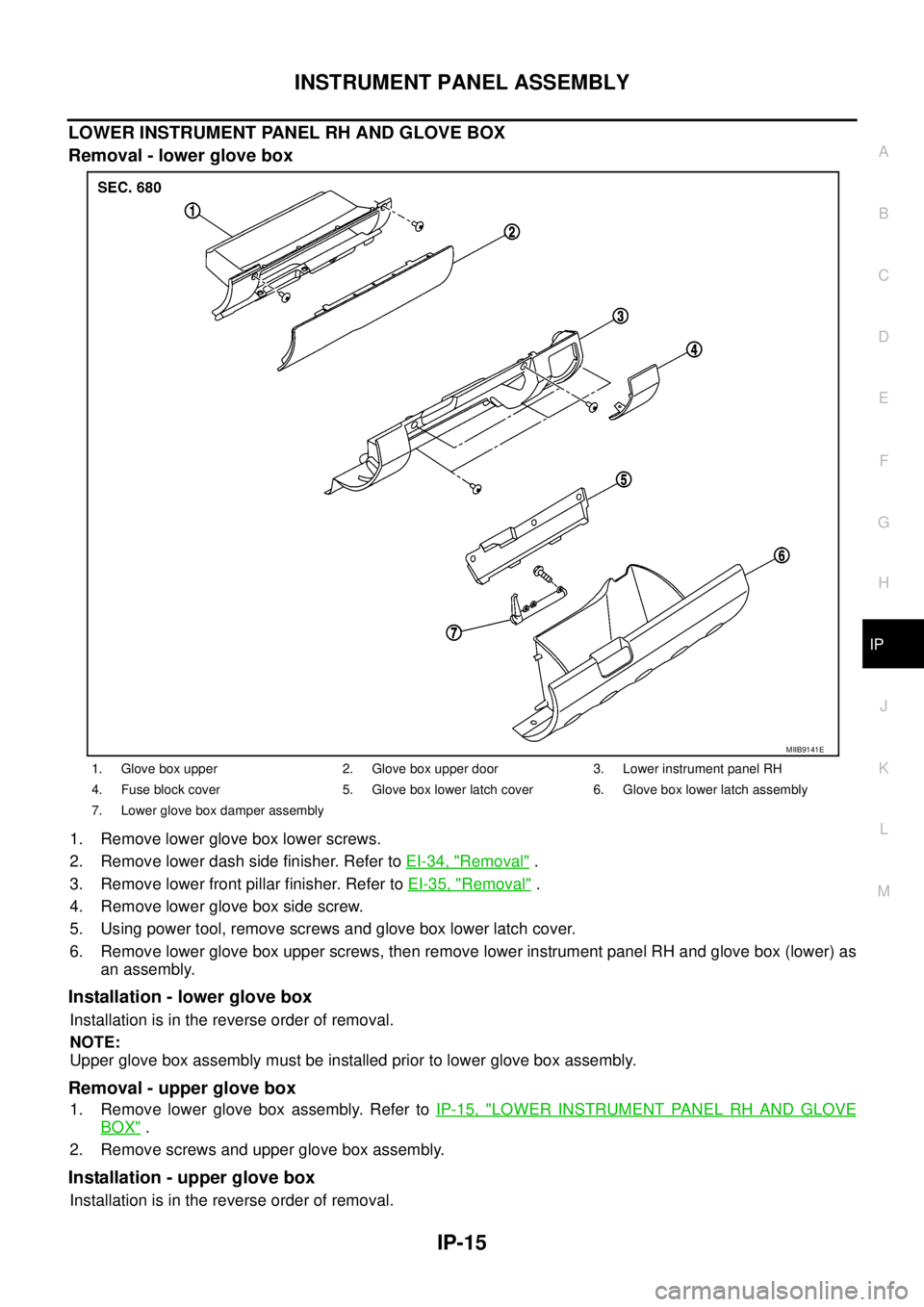
LOWER INSTRUMENT PANEL RH AND GLOVE BOX
Removal - lower glove box
1. Remove lower glove box lower screws.
2. Remove lower dash side finisher. Refer toEI-34, "
Removal".
3. Remove lower front pillar finisher. Refer toEI-35, "
Removal".
4. Remove lower glove box side screw.
5. Using power tool, remove screws and glove box lower latch cover.
6. Remove lower glove box upper screws, then remove lower instrument panel RH and glove box (lower) as
an assembly.
Installation - lower glove box
Installation is in the reverse order of removal.
NOTE:
Upper glove box assembly must be installed prior to lower glove box assembly.
Removal - upper glove box
1. Remove lower glove box assembly. Refer toIP-15, "LOWER INSTRUMENT PANEL RH AND GLOVE
BOX".
2. Remove screws and upper glove box assembly.
Installation - upper glove box
Installation is in the reverse order of removal.
1. Glove box upper 2. Glove box upper door 3. Lower instrument panel RH
4. Fuse block cover 5. Glove box lower latch cover 6. Glove box lower latch assembly
7. Lower glove box damper assembly
MIIB9141E
Page 1775 of 3171
IP-16
INSTRUMENT PANEL ASSEMBLY
CENTER CONSOLE
Removal
1. Remove cup holder finisher.
2. Remove A/T or M/T finisher. Refer toIP-14, "
A/T CONTROL FINISHER (A/T)".
3. Remove RH lower glove box assembly.
4. Remove center console screws.
5. Release center console, rear base, from front base.
6. Disconnect electrical connectors and remove center console.
Installation
Installation is in the reverse order of removal.
1. Center console front base. 2. Center console rear base.
MIIB9142E
Page 1776 of 3171
INSTRUMENT PANEL ASSEMBLY
IP-17
C
D
E
F
G
H
J
K
L
MA
B
IP
Disassembly and AssemblyEIS00DZ0
CENTER CONSOLE
Disassembly
1. Remove the center console. Refer toIP-16, "CENTER CONSOLE".
2. Remove front cup holder insert and assembly.
3. Remove latch from console lid.
4. Remove hinge from console lid. Remove console lid.
5. Remove console bin and reinforcement assembly.
6. Remove rear finisher assembly.
7. Remove rear cup holder assembly.
8. Remove ash tray (if equipped).
9. Remove console bracket.
10. Remove wire harness bracket.
Assembly
Assembly is in the reverse order of disassembly.
MIIB9143E
1. A/T control finisher (A/T) 2. Center console front base 3. Bracket
4. Center console rear base 5. Rear finisher assembly 6. Cup holder
7. Center console bin and reinforce-
ment8. Hinge 9. Center console lid
10. Cup holder finisher 11. Cup holder insert 12. A/T finisher
13. Ashtray
Page 1777 of 3171
IP-18
INSTRUMENT PANEL ASSEMBLY
Page 2153 of 3171
LT-70
HEADLAMP AIMING CONTROL (MANUAL)
Removal and Installation
EKS00P3A
1. Remove lower instrument panel (driver side) (1). Refer toIP-10,
"Removal and Installation".
2. Press headlamp aiming switch (2) fixing pawl (A) and remove
unit from instrument lower panel (driver side) (1).
Switch Circuit InspectionEKS00P3B
Using a circuit tester, check resistance between headlamp aiming
switch connector terminals in each operation status of aiming switch.
SKIB6853E
PKIC0552E
Page 2195 of 3171
LT-112
LIGHTING AND TURN SIGNAL SWITCH
LIGHTING AND TURN SIGNAL SWITCH
PFP:25540
Removal and InstallationEKS00P8N
REMOVAL
1. Remove steering column cover. Refer toIP-10, "INSTRUMENT
PANEL ASSEMBLY".
2. Disconnect lighting and turn signal switch connector.
3. While pressing tabs, pull lighting and turn signal switch toward
driver door and release from the steering column.
INSTALLATION
Installation is the reverse order of removal.
SKIB6473E