2005 NISSAN NAVARA instrument panel
[x] Cancel search: instrument panelPage 2950 of 3171
FRONT PASSENGER AIR BAG MODULE
SRS-41
C
D
E
F
G
I
J
K
L
MA
B
SRS
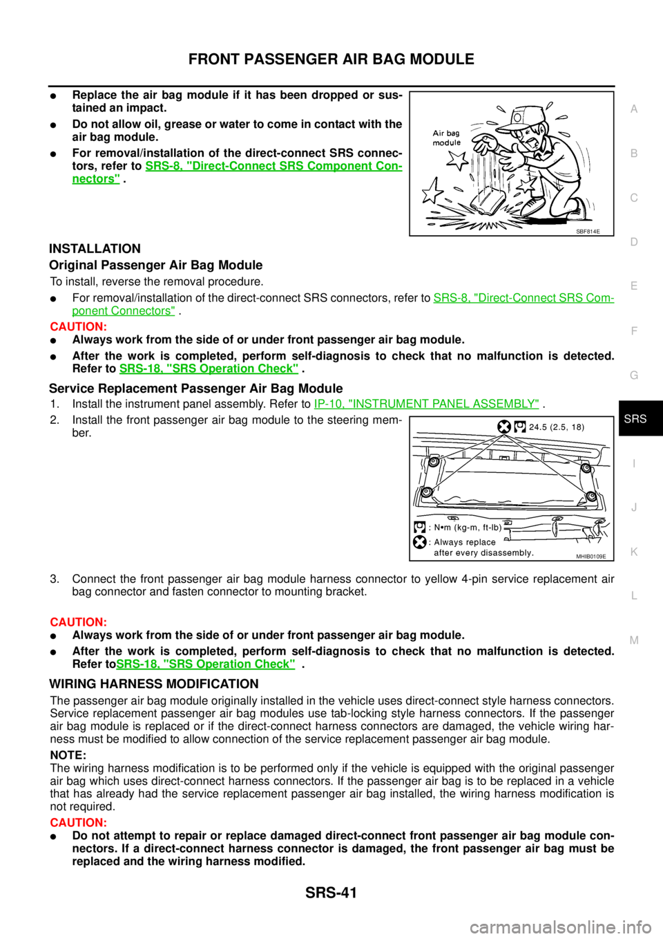
lReplace the air bag module if it has been dropped or sus-
tainedanimpact.
lDo not allow oil, grease or water to come in contact with the
air bag module.
lFor removal/installation of the direct-connect SRS connec-
tors, refer toSRS-8, "
Direct-Connect SRS Component Con-
nectors".
INSTALLATION
Original Passenger Air Bag Module
To install, reverse the removal procedure.
lFor removal/installation of the direct-connect SRS connectors, refer toSRS-8, "Direct-Connect SRS Com-
ponent Connectors".
CAUTION:
lAlways work from the side of or under front passenger air bag module.
lAfter the work is completed, perform self-diagnosis to check that no malfunction is detected.
Refer toSRS-18, "
SRS Operation Check".
Service Replacement Passenger Air Bag Module
1. Install the instrument panel assembly. Refer toIP-10, "INSTRUMENT PANEL ASSEMBLY".
2. Install the front passenger air bag module to the steering mem-
ber.
3. Connect the front passenger air bag module harness connector to yellow 4-pin service replacement air
bag connector and fasten connector to mounting bracket.
CAUTION:
lAlways work from the side of or under front passenger air bag module.
lAfter the work is completed, perform self-diagnosis to check that no malfunction is detected.
Refer toSRS-18, "
SRS Operation Check".
WIRING HARNESS MODIFICATION
The passenger air bag module originally installed in the vehicle uses direct-connect style harness connectors.
Service replacement passenger air bag modules use tab-locking style harness connectors. If the passenger
air bag module is replaced or if the direct-connect harness connectors are damaged, the vehicle wiring har-
ness must be modified to allow connection of the service replacement passenger air bag module.
NOTE:
The wiring harness modification is to be performed only if the vehicle is equipped with the original passenger
air bag which uses direct-connect harness connectors. If the passenger air bag is to be replaced in a vehicle
that has already had the service replacement passenger air bag installed, the wiring harness modification is
not required.
CAUTION:
lDo not attempt to repair or replace damaged direct-connect front passenger air bag module con-
nectors. If a direct-connect harness connector is damaged, the front passenger air bag must be
replaced and the wiring harness modified.
SBF814E
MHIB0109E
Page 2957 of 3171
SRS-48
DIAGNOSIS SENSOR UNIT
DIAGNOSIS SENSOR UNIT
PFP:28556
Removal and InstallationEHS001Y0
REMOVAL
CAUTION:
lBefore servicing the SRS, turn the ignition switch off, disconnect both battery cables and wait at
least 3 minutes.
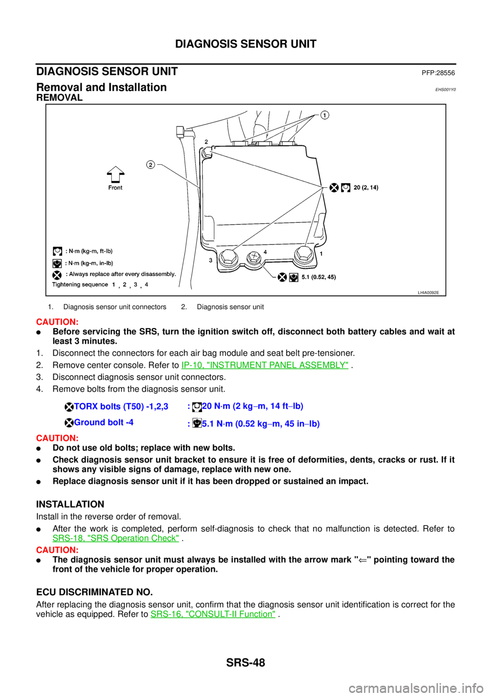
1. Disconnect the connectors for each air bag module and seat belt pre-tensioner.
2. Remove center console. Refer toIP-10, "
INSTRUMENT PANEL ASSEMBLY".
3. Disconnect diagnosis sensor unit connectors.
4. Remove bolts from the diagnosis sensor unit.
CAUTION:
lDo not use old bolts; replace with new bolts.
lCheck diagnosis sensor unit bracket to ensure it is free of deformities, dents, cracks or rust. If it
shows any visible signs of damage, replace with new one.
lReplace diagnosis sensor unit if it has been dropped or sustained an impact.
INSTALLATION
Install in the reverse order of removal.
lAfter the work is completed, perform self-diagnosis to check that no malfunction is detected. Refer to
SRS-18, "
SRS Operation Check".
CAUTION:
lThe diagnosis sensor unit must always be installed with the arrow mark "Ü" pointing toward the
front of the vehicle for proper operation.
ECU DISCRIMINATED NO.
After replacing the diagnosis sensor unit, confirm that the diagnosis sensor unit identification is correct for the
vehicle as equipped. Refer toSRS-16, "
CONSULT-II Function".
LHIA0092E
1. Diagnosis sensor unit connectors 2. Diagnosis sensor unit
TORX bolts (T50) -1,2,3:20N·m(2kg-m, 14 ft-lb)
Ground bolt -4
: 5.1 N·m (0.52 kg-m, 45 in-lb)
Page 2965 of 3171

SRS-56
COLLISION DIAGNOSIS
COLLISION DIAGNOSIS
PFP:00015
For Frontal CollisionEHS001Y3
Check the SRS components using the following table.
lAfter the work is completed, perform self-diagnosis to check that no malfunction is detected. Refer to
SRS-18, "
SRS Operation Check".
SRS INSPECTION (FOR FRONTAL COLLISION)
For Side CollisionEHS001Y4
Check the SRS components using the following table.
Part SRS is activated SRS is NOT activated
Air bag module
(driver and front pas-
senger air bag mod-
ule)Replace
Install with new fas-
teners.1. Remove air bag module. Check harness cover and connectors for damage, termi-
nals for deformities, and harness for binding.
2. Install driver air bag module into the steering wheel to check fit and alignment with
the wheel.
3. Install passenger air bag module into the instrument panel to check fit with the
instrument panel.
4. If no damage is found, reinstall with new fasteners.
5. If damaged—Replace. Install air bag modules with new fasteners.
Air bag modules must be deployed before disposal.
Seat belt pre-
tensioner assembliesReplace
Install seat belt pre-
tensioner with new
fasteners.1. Remove seat belt pre-tensioners.
Check harness cover and connectors for damage, terminals for deformities, and
harness for binding.
2. Check belts for damage and anchors for loose mounting.
3. Check retractor for smooth operation.
4. Check seat belt adjuster for damage.
5. If no damage is found, reinstall seat belt pre-tensioner assembly.
6. If damaged—Replace. Install the seat belt pre-tensioners with new fasteners.
Seat belt pre-tensioners must be deployed before disposal.
Diagnosis sensor unit Replace
Install with new fas-
teners.1. Check case for dents, cracks or deformities.
2. Check connectors for damage, and terminals for deformities.
3. If no damage is found, reinstall with new fasteners.
4. If damaged—Replace. Install diagnosis sensor unit with new fasteners.
Steering wheel 1. Visually check steering wheel for deformities.
2. Check harness (built into steering wheel) and connectors for damage, and terminals for deformities.
3. Install driver air bag module into the steering wheel to check fit and alignment with the wheel.
4. Check steering wheel for excessive free play.
5. If no damage is found, reinstall.
6. If damaged—Replace.
Spiral cable Replace the spiral
cable.1. Visually check spiral cable and combination switch for damage.
2. Check connectors and protective tape for damage.
3. Check steering wheel for noise, binding or heavy operation.
4. If no damage is found, reinstall.
5. If damaged—Replace.
Harness and connec-
tors1. Check connectors for poor connection, damage, and terminals for deformities.
2. Check harness for binding, chafing, cuts, or deformities.
3. If no damage is found, reinstall the harness and connectors.
4. If damaged—Replace the damaged harness. Do not attempt to repair, splice or modify any SRS harness.
Instrument panel
Replace the instru-
ment panel assembly.1. Visually check instrument panel for damage.
2. If no damage is found, reinstall the instrument panel.
3. If damaged—Replace the instrument panel.
Page 3067 of 3171
TF-100
TRANSFER CONTROL UNIT
TRANSFER CONTROL UNIT
PFP:33084
Removal and InstallationEDS0032J
REMOVAL
1. Switch 4WD shift switch to 2WD and set transfer assembly to 2WD.
CAUTION:
When removal transfer control unit, transfer state must be at 2WD or AUTO.
2. Turn the ignition switch OFF and disconnect the battery cables.
3. Remove the lower instrument panel LH (LHD models) or lower instrument panel RH (RHD models). Refer
toIP-13, "
LOWER INSTRUMENT PANEL LH"(LHD models) orIP-13, "LOWER INSTRUMENT PANEL
LH"(RHD models).
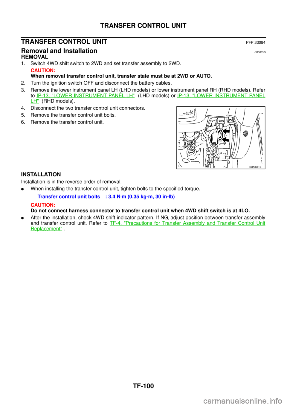
4. Disconnect the two transfer control unit connectors.
5. Remove the transfer control unit bolts.
6. Remove the transfer control unit.
INSTALLATION
Installation is in the reverse order of removal.
lWhen installing the transfer control unit, tighten bolts to the specified torque.
CAUTION:
Do not connect harness connector to transfer control unit when 4WD shift switch is at 4LO.
lAfter the installation, check 4WD shift indicator pattern. If NG, adjust position between transfer assembly
and transfer control unit. Refer toTF-4, "
Precautions for Transfer Assembly and Transfer Control Unit
Replacement".
SDIA3201E
Transfer control unit bolts : 3.4 N·m (0.35 kg-m, 30 in-lb)
Page 3167 of 3171
WW-56
CIGARETTE LIGHTER
Removal and Installation of Cigarette Lighter
EKS00P6M
REMOVAL
1. Remove lower glove box assembly. Refer toIP-10, "INSTRUMENT PANEL ASSEMBLY".
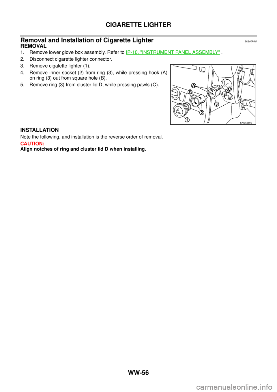
2. Disconnect cigarette lighter connector.
3. Remove cigalette lighter (1).
4. Remove inner socket (2) from ring (3), while pressing hook (A)
on ring (3) out from square hole (B).
5. Remove ring (3) from cluster lid D, while pressing pawls (C).
INSTALLATION
Note the following, and installation is the reverse order of removal.
CAUTION:
Align notches of ring and cluster lid D when installing.
SKIB6859E
Page 3169 of 3171
WW-58
POWER SOCKET
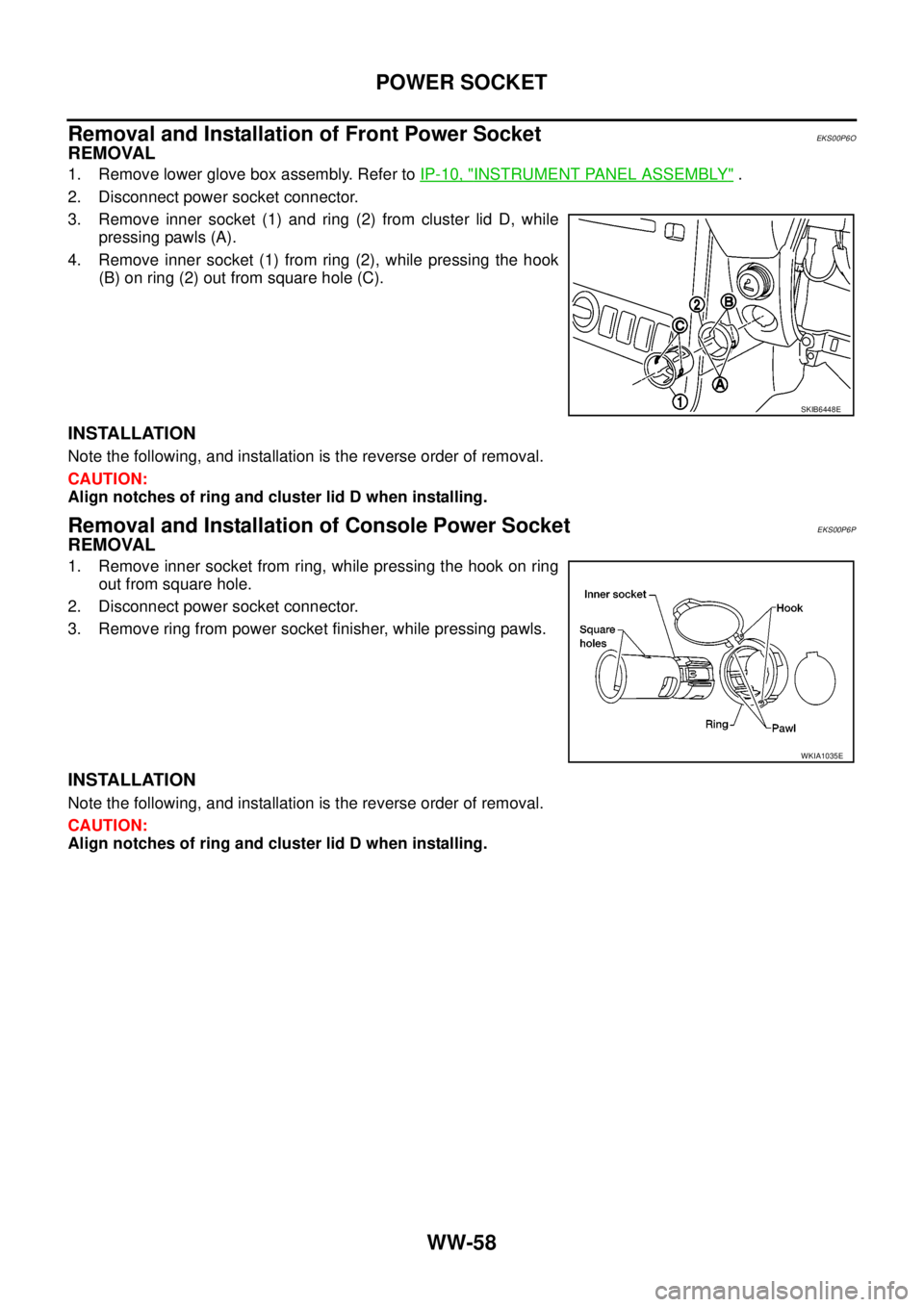
Removal and Installation of Front Power Socket
EKS00P6O
REMOVAL
1. Remove lower glove box assembly. Refer toIP-10, "INSTRUMENT PANEL ASSEMBLY".
2. Disconnect power socket connector.
3. Remove inner socket (1) and ring (2) from cluster lid D, while
pressing pawls (A).
4. Remove inner socket (1) from ring (2), while pressing the hook
(B) on ring (2) out from square hole (C).
INSTALLATION
Note the following, and installation is the reverse order of removal.
CAUTION:
Align notches of ring and cluster lid D when installing.
Removal and Installation of Console Power SocketEKS00P6P
REMOVAL
1. Remove inner socket from ring, while pressing the hook on ring
out from square hole.
2. Disconnect power socket connector.
3. Remove ring from power socket finisher, while pressing pawls.
INSTALLATION
Note the following, and installation is the reverse order of removal.
CAUTION:
Align notches of ring and cluster lid D when installing.
SKIB6448E
WKIA1035E