Page 722 of 3171
BL-138
THEFT WARNING SYSTEM
THEFT WARNING SYSTEM
PFP:28590
Component Parts and Harness Connector LocationEIS00DBW
KING CAB
1. Fuse block (J/B) fuse layout 2. Fuse and fusible link box 3. IPDM E/R fuse layout
4. IPDM E/R E17, E18 5. BCM M42, M43, M44
(View with instrument lower panel
LH removed)6. Door lock/unlock switch M52
7. Rear door switch NO.2 (LH) D72 8. Front door switch (Driver side)
D749. Rear door switch NO.1 (LH) D71
MIIB1033E
Page 723 of 3171
THEFT WARNING SYSTEM
BL-139
C
D
E
F
G
H
J
K
L
MA
B
BL
DOUBLE CAB
10. Hood switch E51 11. a: Security indicator
b: Combination meter M23
MIIB1034E
1. Fuse block (J/B) fuse layout 2. Fuse and fusible link box 3. IPDM E/R fuse layout
4. IPDM E/R E17, E18 5. BCM M42, M43, M44
(View with Instrument lower panel
LH removed)6. Front door switch (Driver side)
B19
7. Rear door switch (LH) B23 8. Door lock/unlock switch M52 9. Hood switch E51
MIIB1031E
Page 754 of 3171
BL-170
NATS(NISSAN ANTI-THEFT SYSTEM)
NATS(NISSAN ANTI-THEFT SYSTEM)
PFP:28591
Component Parts and Harness Connector LocationEIS00DAO
NOTE:
If customer reports a “No start” condition, request ALL KEYS to be brought to an NISSAN dealer in
case of a NATS malfunction.
1. Fuse block (J/B) fuse layout 2. Fuse and fusible link box 3. IPDM fuse layout
4. BCM M42, M43, M44
(View with instrument lower
panel LH removed)5. NATS antenna amp M37 6. a: Security indicator lamp
b: Combination meter M23
7. ECM E20 (Engine room)
MIIB1067E
Page 772 of 3171

BL-188
NATS(NISSAN ANTI-THEFT SYSTEM)
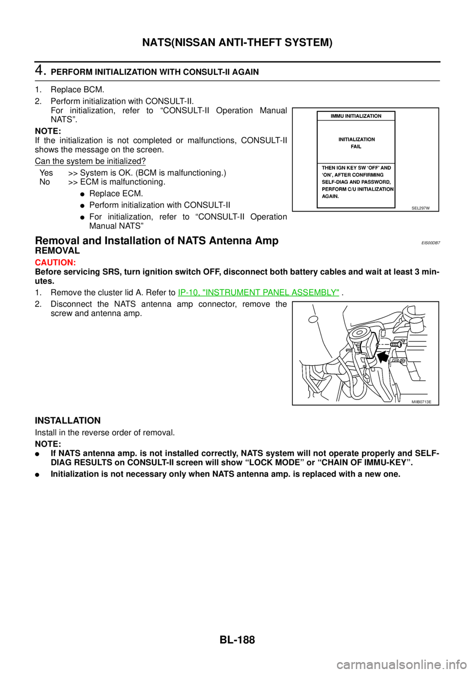
4.PERFORM INITIALIZATION WITH CONSULT-II AGAIN
1. Replace BCM.
2. Perform initialization with CONSULT-II.
For initialization, refer to “CONSULT-II Operation Manual
NATS”.
NOTE:
If the initialization is not completed or malfunctions, CONSULT-II
shows the message on the screen.
Can the system be initialized?
Yes >>SystemisOK.(BCMismalfunctioning.)
No >> ECM is malfunctioning.
lReplace ECM.
lPerform initialization with CONSULT-II
lFor initialization, refer to “CONSULT-II Operation
Manual NATS”
Removal and Installation of NATS Antenna AmpEIS00DB7
REMOVAL
CAUTION:
Before servicing SRS, turn ignition switch OFF, disconnect both battery cables and wait at least 3 min-
utes.
1. Remove the cluster lid A. Refer toIP-10, "
INSTRUMENT PANEL ASSEMBLY".
2. Disconnect the NATS antenna amp connector, remove the
screw and antenna amp.
INSTALLATION
Install in the reverse order of removal.
NOTE:
lIf NATS antenna amp. is not installed correctly, NATS system will not operate properly and SELF-
DIAG RESULTS on CONSULT-II screen will show “LOCK MODE” or “CHAIN OF IMMU-KEY”.
lInitialization is not necessary only when NATS antenna amp. is replaced with a new one.
SEL297W
MIIB0713E
Page 794 of 3171
BR-8
BRAKE PEDAL
Removal and Installation
EFS005SH
COMPONENTS
REMOVAL
1. Remove lower instrument panel LH. Refer toIP-13, "LOWER INSTRUMENT PANEL LH".
2. Remove stop lamp switch and from brake pedal assembly.
3. Remove snap pin and clevis pin from input rod clevis.
4. Remove mounting nuts from pedal bracket, and remove brake
pedal assembly from vehicle.
1. Brake pedal assembly 2. Clip 3. Stop lamp switch
4. Snap pin 5. Brake pedal pad 6. Clevis pin
: Multi-purpose grease
Refer to GI section for symbol marks except in the above.
SFIA3191E
PFIA0435E
Page 937 of 3171
COMBINATION METERS
DI-27
C
D
E
F
G
H
I
J
L
MA
B
DI
Electrical Components InspectionEKS00L8Z
FUEL LEVEL SENSOR UNIT CHECK
For removal, refer toFL-14, "FUEL LEVEL SENSOR UNIT".
Check Fuel Level Sensor Unit
Check resistance between terminals 1 and 2.
*1 and *2: When float rod is in contact with stopper.
AMBIENT SENSOR CHECK
Check resistance between terminals 1 and 2.
Removal and Installation of Combination MeterEKS00L90
1. Remove cluster lid A. Refer toIP-10, "INSTRUMENT PANEL ASSEMBLY".
2. Remove screws (A) and combination meter.
Terminal Float position [mm (in)]Resistance
value [W]
(Approx.)
12*1 Empty 26 (1.02) 80
*2 Full 205 (8.07) 6
SKIB4717E
Terminals Temperature [°C(°F)]Resistance value [kW]
(Approx.)
12–20 (–4) 15.8
–10 (14) 9.60
0 (32) 6.02
10 (50) 3.87
20 (68) 2.55
30 (86) 1.74
40 (104) 1.20
SKIB4844E
SKIB4716E
Page 1299 of 3171

HEAT UP SWITCH
EC-319
C
D
E
F
G
H
I
J
K
L
MA
EC
HEAT UP SWITCHPFP:27666
DescriptionEBS01KMA
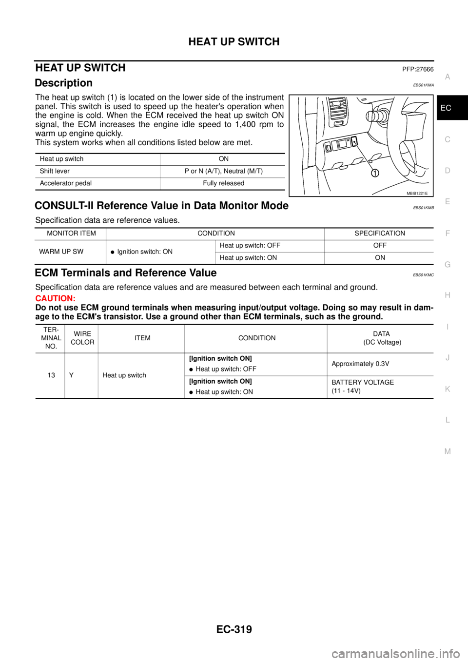
The heat up switch (1) is located on the lower side of the instrument
panel. This switch is used to speed up the heater's operation when
the engine is cold. When the ECM received the heat up switch ON
signal, the ECM increases the engine idle speed to 1,400 rpm to
warm up engine quickly.
This system works when all conditions listed below are met.
CONSULT-II Reference Value in Data Monitor ModeEBS01KMB
Specification data are reference values.
ECM Terminals and Reference ValueEBS01KMC
Specification data are reference values and are measured between each terminal and ground.
CAUTION:
Do not use ECM ground terminals when measuring input/output voltage. Doing so may result in dam-
age to the ECM's transistor. Use a ground other than ECM terminals, such as the ground.
Heat up switch ON
Shift lever P or N (A/T), Neutral (M/T)
Accelerator pedal Fully released
MBIB1221E
MONITOR ITEM CONDITION SPECIFICATION
WARM UP SW
lIgnition switch: ONHeat up switch: OFF OFF
Heat up switch: ON ON
TER-
MINAL
NO.WIRE
COLORITEM CONDITIONDATA
(DC Voltage)
13 Y Heat up switch[Ignition switch ON]
lHeat up switch: OFFApproximately 0.3V
[Ignition switch ON]
lHeat up switch: ONBATTERY VOLTAGE
(11 - 14V)
Page 1339 of 3171

EI-1
EXTERIOR & INTERIOR
IBODY
CONTENTS
C
D
E
F
G
H
J
K
L
M
SECTIONEI
A
B
EI
EXTERIOR & INTERIOR
PRECAUTIONS .......................................................... 3
Service Notice .......................................................... 3
Precautions for Supplemental Restraint System
(SRS)“AIRBAG”and“SEATBELTPRE-TEN-
SIONER” .................................................................. 3
Precautions for SRS “AIR BAG” and “SEAT BELT
PRE-TENSIONER” Service ..................................... 3
Precautions for Procedures without Cowl Top Cover..... 4
PREPARATION ........................................................... 5
Commercial Service Tools ........................................ 5
SQUEAK AND RATTLE TROUBLE DIAGNOSES..... 6
Work Flow ................................................................ 6
CUSTOMER INTERVIEW ..................................... 6
DUPLICATE THE NOISE AND TEST DRIVE ....... 7
CHECK RELATED SERVICE BULLETINS ........... 7
LOCATE THE NOISE AND IDENTIFY THE
ROOT CAUSE ...................................................... 7
REPAIR THE CAUSE ........................................... 7
CONFIRM THE REPAIR ....................................... 7
Generic Squeak and Rattle Troubleshooting ........... 7
INSTRUMENT PANEL .......................................... 7
CENTER CONSOLE ............................................. 8
DOORS ................................................................. 8
TRUNK .................................................................. 8
SUNROOF/HEADLINING ..................................... 8
OVERHEAD CONSOLE (FRONT AND REAR)..... 8
SEATS ................................................................... 9
UNDERHOOD ....................................................... 9
Diagnostic Worksheet ............................................ 10
CLIP AND FASTENER ............................................. 12
Clip and Fastener ................................................... 12
FRONT BUMPER ..................................................... 15
Removal and Installation ........................................ 15
FRONT BUMPER ............................................... 15
REAR BUMPER ....................................................... 17
Removal and Installation ........................................ 17
REMOVAL ........................................................... 17
INSTALLATION ................................................... 18FRONT GRILLE ........................................................ 19
Removal and Installation ........................................ 19
REMOVAL ........................................................... 19
INSTALLATION ................................................... 19
COWL TOP ............................................................... 20
Removal and Installation ........................................ 20
REMOVAL ........................................................... 20
INSTALLATION ................................................... 20
FENDER PROTECTOR ............................................ 21
Components ........................................................... 21
Removal and Installation of Front Fender Protector... 22
REMOVAL ........................................................... 22
INSTALLATION ................................................... 22
Removal and Installation of Rear Fender Protector... 22
REMOVAL ........................................................... 22
INSTALLATION ................................................... 22
MUDGUARD ............................................................. 23
Removal and Installation ........................................ 23
RUNNING BOARDS ................................................. 24
Removal and Installation ........................................ 24
REMOVAL ........................................................... 25
INSTALLATION ................................................... 25
ROOF RACK ............................................................. 26
Removal and Installation ........................................ 26
REMOVAL ........................................................... 26
INSTALLATION ................................................... 26
DOOR OUTSIDE MOLDING ..................................... 27
Removal and Installation ........................................ 27
FRONT DOOR OUTSIDE MOLDING .................. 27
SIDE GUARD MOLDING .......................................... 28
Removal and Installation ........................................ 28
REMOVAL ........................................................... 29
INSTALLATION ................................................... 29
DOOR FINISHER ...................................................... 30
Removal and Installation ........................................ 30
FRONT DOOR .................................................... 30
REAR DOOR - DOUBLE CAB ............................ 31
REAR DOOR - KING CAB .................................. 32
BODY SIDE TRIM ..................................................... 33
Components ........................................................... 33