Page 464 of 3171
ATC-130
MODE DOOR MOTOR
MODE DOOR MOTOR
PFP:27731
ComponentsEJS006CE
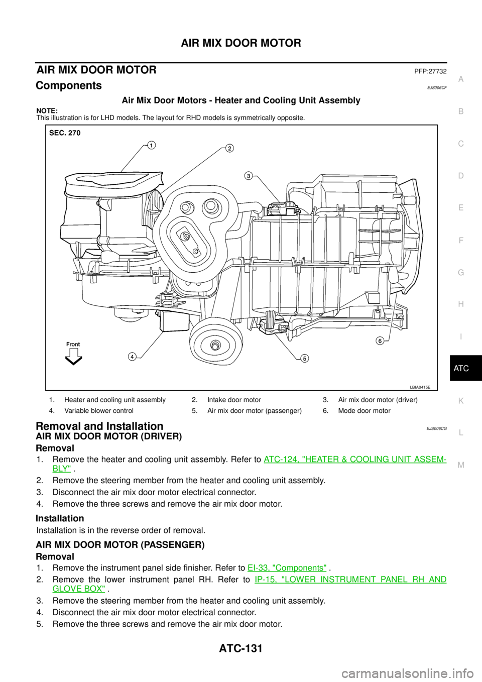
Mode Door Motor - Heater and Cooling Unit Assembly
NOTE:
This illustration is for LHD models. The layout for RHD models is symmetrically opposite.
Removal and InstallationEJS006DE
REMOVAL
1. Remove the instrument panel side finisher. Refer toIP-10, "INSTRUMENT PANEL ASSEMBLY".
2. Remove the lower instrument cover. Refer toIP-10, "
INSTRUMENT PANEL ASSEMBLY".
3. Disconnect the mode door motor electrical connector.
4. Remove the three screws and remove the mode door motor.
INSTALLATION
Installation is in the reverse order of removal.
1. Heater and cooling unit assembly 2. Intake door motor 3. Air mix door motor (driver)
4. Variable blower control 5. Air mix door motor (passenger) 6. Mode door motor
LBIA0415E
Page 465 of 3171

AIR MIX DOOR MOTOR
ATC-131
C
D
E
F
G
H
I
K
L
MA
B
AT C
AIR MIX DOOR MOTORPFP:27732
ComponentsEJS006CF
Air Mix Door Motors - Heater and Cooling Unit Assembly
NOTE:
This illustration is for LHD models. The layout for RHD models is symmetrically opposite.
Removal and InstallationEJS006CG
AIR MIX DOOR MOTOR (DRIVER)
Removal
1. Remove the heater and cooling unit assembly. Refer toATC-124, "HEATER&COOLING UNIT ASSEM-
BLY".
2. Remove the steering member from the heater and cooling unit assembly.
3. Disconnect the air mix door motor electrical connector.
4. Remove the three screws and remove the air mix door motor.
Installation
Installation is in the reverse order of removal.
AIR MIX DOOR MOTOR (PASSENGER)
Removal
1. Remove the instrument panel side finisher. Refer toEI-33, "Components".
2. Remove the lower instrument panel RH. Refer toIP-15, "
LOWER INSTRUMENT PANEL RH AND
GLOVE BOX".
3. Remove the steering member from the heater and cooling unit assembly.
4. Disconnect the air mix door motor electrical connector.
5. Remove the three screws and remove the air mix door motor.
1. Heater and cooling unit assembly 2. Intake door motor 3. Air mix door motor (driver)
4. Variable blower control 5. Air mix door motor (passenger) 6. Mode door motor
LBIA0415E
Page 469 of 3171
DUCTS AND GRILLES
ATC-135
C
D
E
F
G
H
I
K
L
MA
B
AT C
Grilles
10. Front floor ducts 11. Rear floor ducts 12. Rear console duct
13. Center console duct 14. Front console duct
MJIB0329E
1. Headliner 2. Overhead grilles 3. Instrument panel
4. LH side ventilator grille 5. LH ventilator grille 6. RH ventilator grille
7. RH side ventilator grille 8. RH side demister grille
Page 470 of 3171

ATC-136
DUCTS AND GRILLES
Removal and Installation
EJS006CK
CONSOLE DUCTS AND CONSOLE GRILLE
Removal
The center console must be removed and disassembled to remove the console ducts and the console grille.
Refer toIP-16, "
CENTER CONSOLE".
Installation
Installation is in the reverse order of removal.
DEFROSTER NOZZLE
Removal
1. Remove the instrument panel trim. Refer toIP-10, "Removal and Installation".
2. Remove the defroster nozzle.
Installation
Installation is in the reverse order of removal.
RH AND LH SIDE DEMISTER DUCT
Removal
1. Remove the instrument panel trim. Refer toIP-10, "Removal and Installation".
2. Remove the center console. Refer toIP-16, "
CENTER CONSOLE".
3. Remove the RH or LH side demister duct.
Installation
Installation is in the reverse order of removal.
RH AND LH VENTILATOR DUCT
Removal
1. Remove the instrument panel trim. Refer toIP-10, "Removal and Installation".
2. Remove the center console. Refer toIP-16, "
CENTER CONSOLE".
3. Remove the RH or LH ventilator duct.
Installation
Installation is in the reverse order of removal.
CENTER VENTILATOR DUCT
Removal
1. Remove the heater and cooling unit assembly. Refer toATC-126, "REMOVAL".
2. Remove the center console. Refer toIP-16, "
CENTER CONSOLE".
3. Remove the defroster nozzle.
4. Remove the RH and LH ventilator ducts.
5. Remove the RH and LH side demister ducts.
6. Remove the center ventilator duct.
Installation
Installation is in the reverse order of removal.
FLOOR CONNECTOR DUCT
Removal
1. Remove the heater and cooling unit assembly. Refer toATC-126, "REMOVAL".
2. Remove the center console. Refer toIP-16, "
CENTER CONSOLE".
3. Remove the floor connector duct.
Installation
Installation is in the reverse order of removal.
Page 561 of 3171
REMOVAL AND INSTALLATION
AV-73
C
D
E
F
G
H
I
J
L
MA
B
AV
REMOVAL AND INSTALLATIONPFP:00000
Auido Unit (1CD Player Type)EKS00Q6U
REMOVAL
1. Remove cluster lid C. Refer toIP-10, "INSTRUMENT PANEL ASSEMBLY".
2. Remove screws (A) . Then remove audio unit (1) from vehicle.
INSTALLATION
Installation is the reverse order of removal.
Audio Unit ( 6CD Player Type ) Without NAVIEKS00Q6V
REMOVAL
1. Remove cluster lid C. Refer toIP-10, "INSTRUMENT PANEL ASSEMBLY".
2. Remove screws (A) . Then remove audio unit (1) from vehicle.
INSTALLATION
Installation is the reverse order of removal.
SKIB3890E
SKIB4405E
Page 562 of 3171
AV-74
REMOVAL AND INSTALLATION
Audio Unit (6CD Player Type) With NAVI
EKS00Q6W
REMOVAL
1. Remove cluster lid C. Refer toIP-10, "INSTRUMENT PANEL ASSEMBLY".
2. Remove screws (A). Then remove audio unit (1) from vehicle.
INSTALLATION
Installation is the reverse order of removal.
Front Door SpeakerEKS00Q6X
REMOVAL
1. Remove door finisher (front) . Refer toEI-30, "DOOR FINISHER".
2. Remove screws (A) and remove speaker (1).
INSTALLATION
Installation is the reverse order of removal.
Rear Door SpeakerEKS00Q6Y
REMOVAL
1. Remove door finisher (rear) . Refer toEI-30, "DOOR FINISHER".
2. Remove screws (A) and remove speaker (1).
INSTALLATION
Installation is the reverse order of removal.
SKIB4580E
SKIB3905E
SKIB3906E
Page 565 of 3171
REMOVAL AND INSTALLATION
AV-77
C
D
E
F
G
H
I
J
L
MA
B
AV
Display UnitEKS00Q73
REMOVAL
1. Remove cluster lid C. Refer toIP-10, "INSTRUMENT PANEL ASSEMBLY".
2. Disconnect connectors.
3. Remove screws (A) and remove display unit (1).
INSTALLATION
Installation is the reverse order of removal.
AV S w i t c hEKS00Q74
REMOVAL
1. Remove cluster lid C (1). Refer toIP-10, "INSTRUMENT PANEL
ASSEMBLY".
2. Remove screws (A).
3. Remove AV switch (2) from cluster lid C (1).
INSTALLATION
Installation is the reverse order of removal.
MicrophoneEKS00Q75
REMOVAL
1. Remove roof console (1). Refer toEI-40, "HEADLINING".
2. Disconnect connector (2).
3. Raise tab (3) and remove microphone (4).
INSTALLATION
Installation is the reverse order of removal.
SKIB4586E
SKIB4587E
SKIB4589E
Page 583 of 3171
BCM (BODY CONTROL MODULE)
BCS-17
C
D
E
F
G
H
I
J
L
MA
B
BCS
ConfigurationEKS00PA6
Refer toGI-37, "Configuration (BCM)".
Removal and Installation of BCMEKS00PA7
REMOVAL
CAUTION:
If possible, before removing BCM, retrieve current BCM configuration to use for reference when con-
figuring brand-new BCM after installation. Refer toGI-37, "
Configuration (BCM)".
1. Disconnect the battery cable from the negative terminal.
2. Remove lower instrument panel LH. Refer toIP-10, "
Removal and Installation".
3. Remove nuts (A) and release BCM (1).
4. Disconnect connectors and then remove BCM (1).
INSTALLATION
Installation is the reverse order of removal.
NOTE:
lWhen replacing BCM, it must be configured. Refer toGI-37, "Configuration (BCM)".
lWhen replacing BCM, perform initialization of NATS system and registration of all NATS ignition key IDs.
Refer toBL-170, "
NATS(Nissan Anti-Theft System)".
PKIC1222E