Page 1645 of 3171
HOW TO USE THIS MANUAL
GI-23
C
D
E
F
G
H
I
J
K
L
MB
GI
AbbreviationsEAS001GZ
The followingABBREVIATIONSare used:
ABBREVIATION DESCRIPTION
A/C Air Conditioner
A/T Automatic Transaxle/Transmission
ATF Automatic Transmission Fluid
D
1Drive range 1st gear
D
2Drive range 2nd gear
D
3Drive range 3rd gear
D
4Drive range 4th gear
FR, RR Front, Rear
LH, RH Left-Hand, Right-Hand
M/T Manual Transaxle/Transmission
OD Overdrive
P/S Power Steering
SAE Society of Automotive Engineers, Inc.
SDS Service Data and Specifications
SST Special Service Tools
2WD 2-Wheel Drive
2
22nd range 2nd gear
2
12nd range 1st gear
1
21st range 2nd gear
1
11st range 1st gear
Page 1646 of 3171

GI-24
SERVICE INFORMATION FOR ELECTRICAL INCIDENT
SERVICE INFORMATION FOR ELECTRICAL INCIDENT
PFP:00000
How to Perform Efficient Diagnosis for an Electrical IncidentEAS001H0
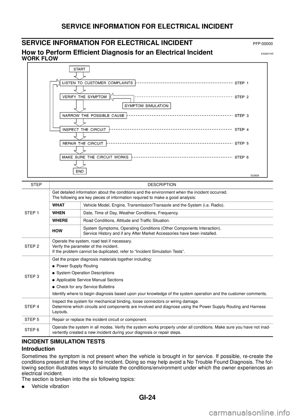
WORK FLOW
INCIDENT SIMULATION TESTS
Introduction
Sometimes the symptom is not present when the vehicle is brought in for service. If possible, re-create the
conditions present at the time of the incident. Doing so may help avoid a No Trouble Found Diagnosis. The fol-
lowing section illustrates ways to simulate the conditions/environment under which the owner experiences an
electrical incident.
The section is broken into the six following topics:
lVehicle vibration
SGI838
STEP DESCRIPTION
STEP 1Get detailed information about the conditions and the environment when the incident occurred.
The following are key pieces of information required to make a good analysis:
WHATVehicle Model, Engine, Transmission/Transaxle and the System (i.e. Radio).
WHENDate, Time of Day, Weather Conditions, Frequency.
WHERERoad Conditions, Altitude and Traffic Situation.
HOWSystem Symptoms, Operating Conditions (Other Components Interaction).
Service History and if any After Market Accessories have been installed.
STEP 2Operate the system, road test if necessary.
Verify the parameter of the incident.
If the problem cannot be duplicated, refer to “Incident Simulation Tests”.
STEP 3Get the proper diagnosis materials together including:
lPower Supply Routing
lSystem Operation Descriptions
lApplicable Service Manual Sections
lCheck for any Service Bulletins
Identify where to begin diagnosis based upon your knowledge of the system operation and the customer comments.
STEP 4Inspect the system for mechanical binding, loose connectors or wiring damage.
Determine which circuits and components are involved and diagnose using the Power Supply Routing and Harness
Layouts.
STEP 5 Repair or replace the incident circuit or component.
STEP 6Operate the system in all modes. Verify the system works properly under all conditions. Make sure you have not inad-
vertently created a new incident during your diagnosis or repair steps.
Page 1647 of 3171

SERVICE INFORMATION FOR ELECTRICAL INCIDENT
GI-25
C
D
E
F
G
H
I
J
K
L
MB
GI
lHeat sensitive
lFreezing
lWater intrusion
lElectrical load
lCold or hot start up
Get a thorough description of the incident from the customer. It is important for simulating the conditions of the
problem.
Vehicle Vibration
The problem may occur or become worse while driving on a rough road or when engine is vibrating (idle with
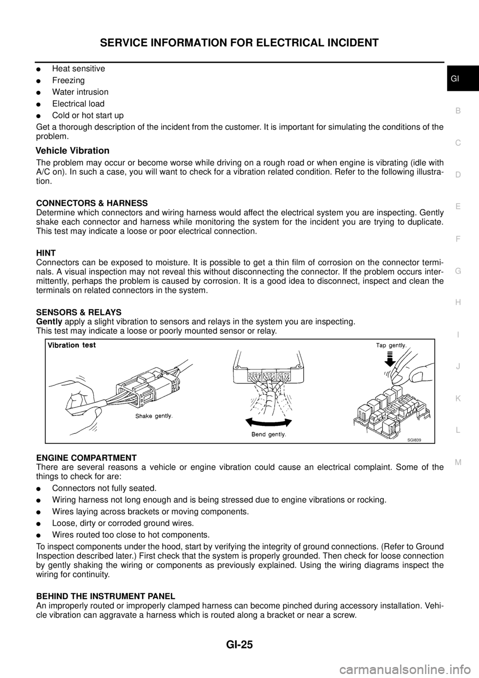
A/C on). In such a case, you will want to check for a vibration related condition. Refer to the following illustra-
tion.
CONNECTORS & HARNESS
Determine which connectors and wiring harness would affect the electrical system you are inspecting. Gently
shake each connector and harness while monitoring the system for the incident you are trying to duplicate.
This test may indicate a loose or poor electrical connection.
HINT
Connectors can be exposed to moisture. It is possible to get a thin film of corrosion on the connector termi-
nals. A visual inspection may not reveal this without disconnecting the connector. If the problem occurs inter-
mittently, perhaps the problem is caused by corrosion. It is a good idea to disconnect, inspect and clean the
terminals on related connectors in the system.
SENSORS & RELAYS
Gentlyapply a slight vibration to sensors and relays in the system you are inspecting.
This test may indicate a loose or poorly mounted sensor or relay.
ENGINE COMPARTMENT
There are several reasons a vehicle or engine vibration could cause an electrical complaint. Some of the
things to check for are:
lConnectors not fully seated.
lWiring harness not long enough and is being stressed due to engine vibrations or rocking.
lWires laying across brackets or moving components.
lLoose, dirty or corroded ground wires.
lWires routed too close to hot components.
To inspect components under the hood, start by verifying the integrity of ground connections. (Refer to Ground
Inspection described later.) First check that the system is properly grounded. Then check for loose connection
by gently shaking the wiring or components as previously explained. Using the wiring diagrams inspect the
wiring for continuity.
BEHIND THE INSTRUMENT PANEL
An improperly routed or improperly clamped harness can become pinched during accessory installation. Vehi-
cle vibration can aggravate a harness which is routed along a bracket or near a screw.
SGI839
Page 1669 of 3171

CONSULT-II CHECKING SYSTEM
GI-47
C
D
E
F
G
H
I
J
K
L
MB
GI
CONSULT-II CHECKING SYSTEMPFP:00000
DescriptionEAS001H2
lCONSULT-II is a hand-held type tester. When it is connected with a diagnostic connector equipped on the
vehicle side, it will communicate with the control unit equipped in the vehicle and then enable various
kinds of diagnostic tests.
lRefer to “CONSULT-II Software Operation Manual” for more information.
Function and System ApplicationEAS001H3
x: Applicable
*: Nissan Anti-Theft SystemDiagnostic test
modeFunction
ENGINE
A/T
AIR BAG
ABS
ALL MODE AWD/4WD
BCM
IPDM E/R
MULTI AV
METER
NATS *
Work supportThis mode enables a technician to adjust some devices
faster and more accurately by following the indications
on CONSULT-II.x---´´--- -
Self-diagnostic
resultsSelf-diagnostic results can be read and erased quickly. x x x x x´´´´x
Trouble diagnostic
recordCurrent self-diagnostic results and all trouble diagnostic
records previously stored can be read.--x------ -
Data monitor Input/Output data in the ECU can be read. x x - x x´´´´-
CAN diagnosis
support monitorThe communication condition of CAN communication
line can be indicated.xx - xx´´´´-
Active testDiagnostic Test Mode in which CONSULT-II drives some
actuators apart from the ECU and also shifts some
parameters in a specified range.x- -x-´´-- -
DTC confirmationThe results of SRT (System Readiness Test) and the
self-diagnosis status/result can be confirmed.x----- - -- -
DTC work supportThe operating condition to confirm Diagnosis Trouble
Codes can be selected.-x------- -
ECM (ECU/TCM)
part numberECM (ECU/TCM) part number can be read. x x - x x´-´--
ECU discrimi-
nated No.Classification number of a replacement ECU can be read
to prevent an incorrect ECU from being installed.--x------ -
Function testThis mode can show results of self-diagnosis of ECU
with either “OK” or “NG”. For engines, more practical
tests regarding sensor/switches and/or actuators are
available.xxxx-- - - - -
Control unit initial-
izationAll registered ignition key IDs in NATS components can
be initialized and new IDs can be registered.------ - -- x
AV C O M M m o n i t o rIndicates the communication condition of AV communi-
cation.- ----- -´--
ConfigurationThe vehicle configuration can be read and written on
brand-new ECU- ----´--- -
Page 1671 of 3171

CONSULT-II CHECKING SYSTEM
GI-49
C
D
E
F
G
H
I
J
K
L
MB
GI
Checking EquipmentEAS001H5
When ordering the following equipment, contact your NISSAN/INFINITI distributor.
CAUTION:
lPrevious CONSULT-II “I” and “Y” DLC-I and DLC-II cables should NOT be used anymore because
their DDL connector pins can be damaged during cable swapping.
lIf CONSULT-ll is used with no connection of CONSULT-ll CONVERTER, malfunctions might be
detected in self-diagnosis depending on control unit which carries out CAN communication.
lIf CONVERTER is not connected with CONSULT-ll, vehicle occur the "FAIL-SAFE MODE" which is
"LIGHT UP the HEADLIGHT" and/or "Cooling FAN ROTATING" when CONSULT-ll is started.
NOTE:
lThe CONSULT-II must be used in conjunction with a program card.
CONSULT-II does not require loading (Initialization) procedure.
lBe sure the CONSULT-II is turned off before installing or removing a program card.
CONSULT-II Start ProcedureEAS001H6
Turning ignition switch off when performing CAN diagnosis could cause CAN memory to be erased.
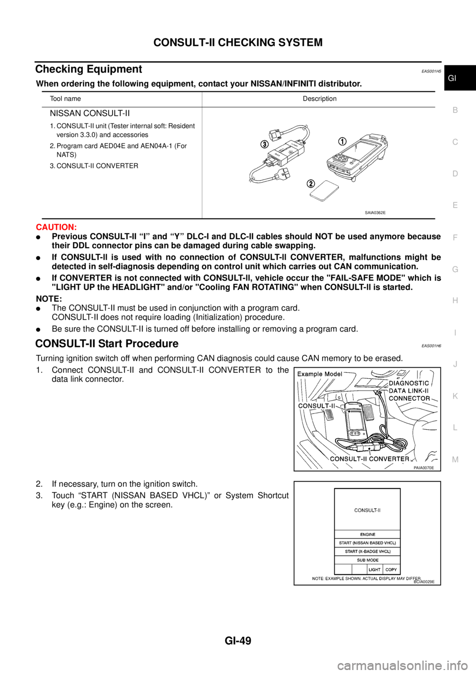
1. Connect CONSULT-II and CONSULT-II CONVERTER to the
data link connector.
2. If necessary, turn on the ignition switch.
3. Touch “START (NISSAN BASED VHCL)” or System Shortcut
key (e.g.: Engine) on the screen.
Tool nameDescription
NISSAN CONSULT-II
1. CONSULT-II unit (Tester internal soft: Resident
version 3.3.0) and accessories
2. Program card AED04E and AEN04A-1 (For
NATS)
3. CONSULT-II CONVERTER
SAIA0362E
PAIA0070E
BCIA0029E
Page 1678 of 3171
GI-56
IDENTIFICATION INFORMATION
IDENTIFICATION INFORMATION
PFP:00010
Model VariationEAS001DM
MAIB0022E
Body Handle Engine Drive Type Transfar Transmission Grade Model
King CabRHD
YD25DDTi4WD TX15B
FS6R31A (6MT)XE BVLNRRY-UQN
SE BVLNRTY-UQN
LHDXE BVLNLRY-UQN
SE BVLNLTY-UQN
2WD — XE BVLALRY-UQN
Double CabRHD
4WD TX15BSECVLNRTY-UQN
RE5R05A (5AT) CVLNRTN-UQN
FS6R31A (6MT)XE CVLNRRYUQN
LHDSECVLNLTY-UQN
RE5R05A (5AT) CVLNLTN-UQN
FS6R31A (6MT)XE CVLNLRY-UQN
2WD — SECVLALTY-UQN
RE5R05A (5AT) CVLALTN-UQN
Page 1680 of 3171
GI-58
IDENTIFICATION INFORMATION
IDENTIFICATION PLATE
ENGINE SERIAL NUMBER
TRANSFER SERIAL NUMBER
AUTOMATIC TRANSMISSION NUMBER
MAIB0014E
MAIB0009E
AGI108
PAIA0054E
Page 1683 of 3171

TERMINOLOGY
GI-61
C
D
E
F
G
H
I
J
K
L
MB
GI
TERMINOLOGYPFP:00011
ISO 15031-2 Terminology ListEAS001H9
All emission related terms used in this publication in accordance with ISO 15031-2 are listed. Accordingly, new
terms, new acronyms/abbreviations and old terms are listed in the following chart.
NEW TERMNEW ACRONYM /
ABBREVIATIONOLD TERM
Air cleaner ACL Air cleaner
Barometric pressure BARO ***
Barometric pressure sensor-BCDD BAROS-BCDD BCDD
Camshaft position CMP ***
Camshaft position sensor CMPS Crank angle sensor
Canister *** Canister
Carburetor CARB Carburetor
Charge air cooler CAC Intercooler
Closed loop CL Closed loop
Closed throttle position switch CTP switch Idle switch
Clutch pedal position switch CPP switch Clutch switch
Continuous fuel injection system CFI system ***
Continuous trap oxidizer system CTOX system ***
Crankshaft position CKP ***
Crankshaft position sensor CKPS ***
Data link connector DLC ***
Data link connector for CONSULT-II DLC for CONSULT-II Diagnostic connector for CONSULT-II
Diagnostic test mode DTM Diagnostic mode
Diagnostic test mode selector DTM selector Diagnostic mode selector
Diagnostic test mode I DTM I Mode I
Diagnostic test mode II DTM II Mode II
Diagnostic trouble code DTC Malfunction code
Direct fuel injection system DFI system ***
Distributor ignition system DI system Ignition timing control
Early fuel evaporation-mixture heater EFE-mixture heater Mixture heater
Early fuel evaporation system EFE system Mixture heater control
Electrically erasable programmable read
only memoryEEPROM ***
Electronic ignition system EI system Ignition timing control
Engine control EC ***
Engine control module ECM ECCS control unit
Engine coolant temperature ECT Engine temperature
Engine coolant temperature sensor ECTS Engine temperature sensor
Engine modification EM ***
Engine speed RPM Engine speed
Erasable programmable read only memory EPROM ***
Evaporative emission canister EVAP canister Canister
Evaporative emission system EVAP system Canister control solenoid valve
Exhaust gas recirculation valve EGR valve EGR valve