Page 1591 of 3171
FUEL COOLER
FL-7
C
D
E
F
G
H
I
J
K
L
MA
FL
FUEL COOLERPFP:17511
Components (4WD Models Only)EBS01FEY
Removal and Installation (4WD Models Only)EBS01FEZ
REMOVAL
WARNING:
Be sure to read “General Precautions” when working on fuel system. Refer toFL-3, "
General Precau-
tions".
1. Remove protector (fuel tube).
2. Remove protector (fuel cooler) mounting bolts (3 pieces) then disconnect fuel tubes from fuel cooler
assembly.
CAUTION:
lPlug fuel tubes and fuel cooler assembly to prevent fuel from draining.
lDo not splash fuel during removal. If fuel is splashed, immediately wipe it off.
3. Remove fuel cooler assembly from protector (fuel cooler)
CAUTION:
lDo not bend fuel tubes during removal.
lAvoid impacts such as falling when handling components.
1. Fuel tube (return) (to fuel tank) 2. Fuel tube (return) (to engine) 3. Bracket
4. Protector (fuel cooler) 5. Protector (fuel tube) 6. Fuel cooler assembly
7. Bracket
PBIC4059E
Page 1592 of 3171
FL-8
FUEL COOLER
INSTALLATION
Note the following, and install in the reverse order of removal.
lInsert hose to the length below when there is no spool on the fuel tube and surely clamp fuel hoses.
lBe sure hose clamp is not positioned on swelled area of fuel tube.
INSPECTION AFTER INSTALLATION
Make sure there is no fuel leakage at connections in the following steps.
lStart engine and rev it up and make sure there is no fuel leakage at connections.Fuel hose : 25 mm (0.98 in)
Page 1597 of 3171
FUEL TANK
FL-13
C
D
E
F
G
H
I
J
K
L
MA
FL
lPull the tube and connector to make sure they are securely
connected.
INSPECTION AFTER INSTALLATION
Make sure there is no fuel leakage at connections in the following step.
lStart engine and rev it up and make sure there is no fuel leakage at connections.
PBIC1653E
Page 1599 of 3171
FUEL LEVEL SENSOR UNIT
FL-15
C
D
E
F
G
H
I
J
K
L
MA
FL
INSTALLATION
Note the following, and install in the reverse order of removal.
lInstall fuel level sensor unit (1) with aligning mating marks (A) on
fuel tank and fuel level sensor unit as shown in the figure.
lInstall lock ring (1), and tighten lock ring by hand. Then tighten
lock ring with a fuel tank lock ring wrench (commercial service
tool), aligning mating marks (A) on fuel tank and lock ring as
showninthefigure.
INSPECTION AFTER INSTALLATION
Make sure there is no fuel leakage at connections in the following steps.
lStart engine and rev it up and make sure there is no fuel leakage at connections.
: Vehicle front
PBIC3506E
: Vehicle front
PBIC3632E
Page 1602 of 3171
FSU-2
PRECAUTIONS
PRECAUTIONS
PFP:00001
PrecautionsEES002KG
lWhen installing the rubber bushings, the final tightening must be done under unladen condition and with
the tires on level ground. Oil will shorten the life of the rubber bushings, so wipe off any spilled oil immedi-
ately.
lUnladen condition means the fuel tank, engine coolant and lubricants are at the full specification. The
spare tire, jack, hand tools, and mats are in their designated positions.
lAfter installing suspension components, check the wheel alignment.
lLock nuts are not reusable. Always use new lock nuts for installation. New lock nuts are pre-oiled, do not
apply any additional lubrication.
Page 1609 of 3171

ON-VEHICLE SERVICE
FSU-9
C
D
F
G
H
I
J
K
L
MA
B
FSU
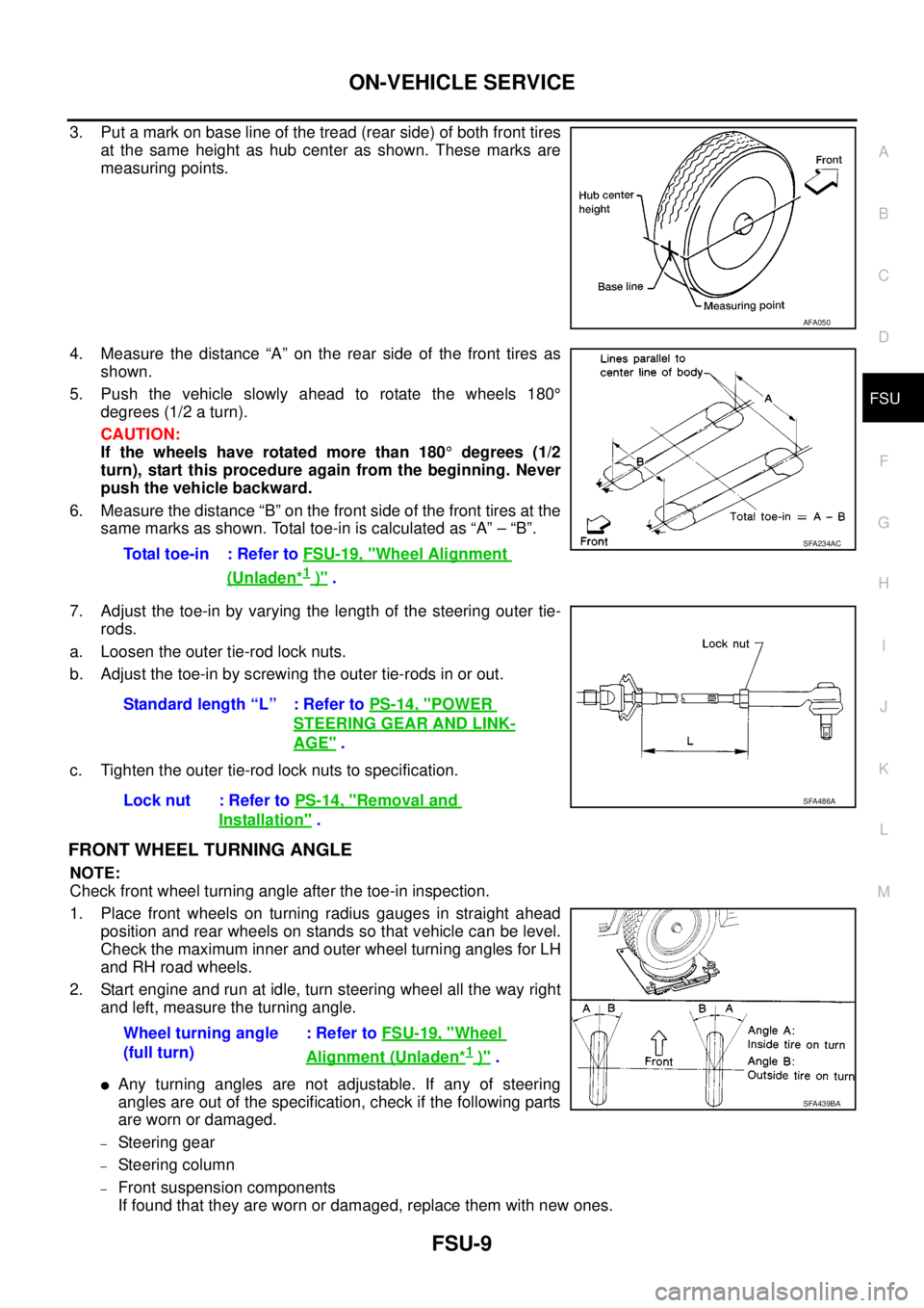
3. Put a mark on base line of the tread (rear side) of both front tires
at the same height as hub center as shown. These marks are
measuring points.
4. Measure the distance “A” on the rear side of the front tires as
shown.
5. Push the vehicle slowly ahead to rotate the wheels 180°
degrees (1/2 a turn).
CAUTION:
If the wheels have rotated more than 180°degrees (1/2
turn), start this procedure again from the beginning. Never
push the vehicle backward.
6. Measure the distance “B” on the front side of the front tires at the
same marks as shown. Total toe-in is calculated as “A” – “B”.
7. Adjust the toe-in by varying the length of the steering outer tie-
rods.
a. Loosen the outer tie-rod lock nuts.
b. Adjust the toe-in by screwing the outer tie-rods in or out.
c. Tighten the outer tie-rod lock nuts to specification.
FRONT WHEEL TURNING ANGLE
NOTE:
Check front wheel turning angle after the toe-in inspection.
1. Place front wheels on turning radius gauges in straight ahead
position and rear wheels on stands so that vehicle can be level.
Check the maximum inner and outer wheel turning angles for LH
and RH road wheels.
2. Start engine and run at idle, turn steering wheel all the way right
and left, measure the turning angle.
lAny turning angles are not adjustable. If any of steering
angles are out of the specification, check if the following parts
are worn or damaged.
–Steering gear
–Steering column
–Front suspension components
If found that they are worn or damaged, replace them with new ones.
AFA050
Total toe-in : Refer toFSU-19, "Wheel Alignment
(Unladen*1)".
SFA234AC
Standard length “L” : Refer toPS-14, "POWER
STEERING GEAR AND LINK-
AGE".
Lock nut : Refer toPS-14, "
Removal and
Installation".
SFA486A
Wheel turning angle
(full turn):RefertoFSU-19, "Wheel
Alignment (Unladen*1)".
SFA439BA
Page 1612 of 3171
FSU-12
STABILIZER BAR
STABILIZER BAR
PFP:54611
Removal and InstallationEES002KQ
REMOVAL
1. Remove the front valance center.
2. Remove engine undercover.
3. Remove connecting rod nuts, as shown.
4. Loosen top bolts for stabilizer bar mounting brackets, then
remove lower bolts from mounting brackets and remove stabi-
lizer bar.
5. Remove bushings from stabilizer bar.
INSPECTION AFTER REMOVAL
lCheck stabilizer bar for twist and deformation. Replace if necessary.
lCheck rubber bushing for cracks, wear and deterioration. Replace if necessary.
INSTALLATION
Installation is in the reverse order of removal.
lTighten all nuts and bolts to specification with vehicle under unladen conditions. Refer toFSU-6, "Compo-
nents".
WEIA0118E
Page 1619 of 3171

SERVICE DATA AND SPECIFICATIONS (SDS)
FSU-19
C
D
F
G
H
I
J
K
L
MA
B
FSU
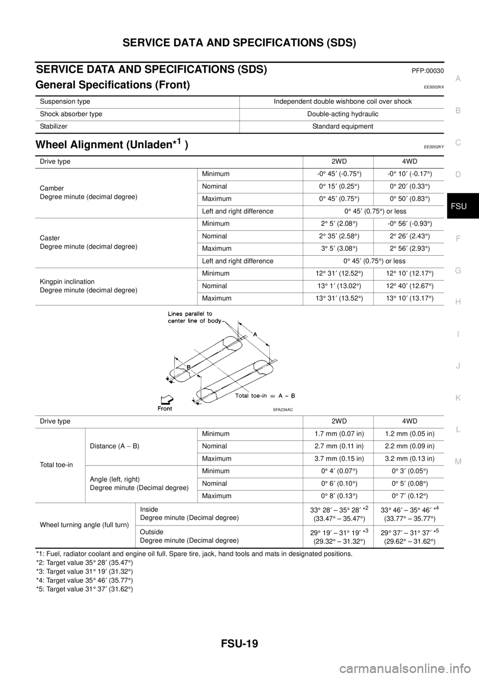
SERVICE DATA AND SPECIFICATIONS (SDS)PFP:00030
General Specifications (Front)EES002KX
Wheel Alignment (Unladen*1)EES002KY
*1: Fuel, radiator coolant and engine oil full. Spare tire, jack, hand tools and mats in designated positions.
*2: Target value 35°28¢(35.47°)
*3: Target value 31°19¢(31.32°)
*4: Target value 35°46¢(35.77°)
*5: Target value 31°37¢(31.62°) Suspension type Independent double wishbone coil over shock
Shock absorber type Double-acting hydraulic
StabilizerStandard equipment
Drive type2WD 4WD
Camber
Degree minute (decimal degree)Minimum -0°45¢(-0.75°)-0°10¢(-0.17°)
Nominal 0°15¢(0.25°)0°20¢(0.33°)
Maximum 0°45¢(0.75°)0°50¢(0.83°)
Left and right difference 0°45¢(0.75°)orless
Caster
Degree minute (decimal degree)Minimum 2°5¢(2.08°)-0°56¢(-0.93°)
Nominal 2°35¢(2.58°)2°26¢(2.43°)
Maximum 3°5¢(3.08°)2°56¢(2.93°)
Left and right difference 0°45¢(0.75°)orless
Kingpin inclination
Degree minute (decimal degree)Minimum 12°31¢(12.52°)12°10¢(12.17°)
Nominal 13°1¢(13.02°)12°40¢(12.67°)
Maximum 13°31¢(13.52°)13°10¢(13.17°)
Drive type2WD 4WD
Total toe-inDistance (A-B)Minimum 1.7 mm (0.07 in) 1.2 mm (0.05 in)
Nominal 2.7 mm (0.11 in) 2.2 mm (0.09 in)
Maximum 3.7 mm (0.15 in) 3.2 mm (0.13 in)
Angle (left, right)
Degree minute (Decimal degree)Minimum 0°4¢(0.07°)0°3¢(0.05°)
Nominal 0°6¢(0.10°)0°5¢(0.08°)
Maximum 0°8¢(0.13°)0°7¢(0.12°)
Wheel turning angle (full turn)Inside
Degree minute (Decimal degree)33°28¢–35°28¢*
2
(33.47°– 35.47°)33°46¢–35°46¢*
4
(33.77°– 35.77°)
Outside
Degree minute (Decimal degree)29°19¢–31°19¢*
3
(29.32°– 31.32°)29°37¢–31°37¢*
5
(29.62°– 31.62°)
SFA234AC