Page 1235 of 3171
DTC P1273 FUEL PUMP
EC-255
C
D
E
F
G
H
I
J
K
L
MA
EC
Diagnostic ProcedureEBS01KJW
1.CHECK INJECTOR ADJUSTMENT VALUE
1. Turn ignition switch ON.
2. Select “ENTER INJECTOR CALIB DATA” in “WORK SUP-
PORT” mode with CONSULT-II.
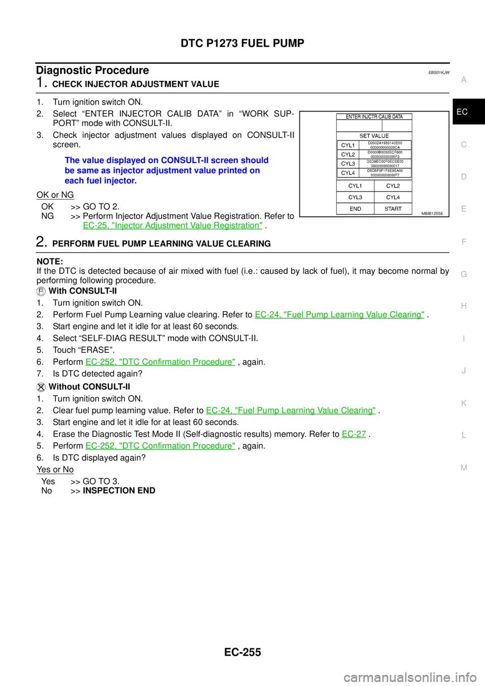
3. Check injector adjustment values displayed on CONSULT-II
screen.
OK or NG
OK >> GO TO 2.
NG >> Perform Injector Adjustment Value Registration. Refer to
EC-25, "
Injector Adjustment Value Registration".
2.PERFORM FUEL PUMP LEARNING VALUE CLEARING
NOTE:
If the DTC is detected because of air mixed with fuel (i.e.: caused by lack of fuel), it may become normal by
performing following procedure.
With CONSULT-II
1. Turn ignition switch ON.
2. Perform Fuel Pump Learning value clearing. Refer toEC-24, "
Fuel Pump Learning Value Clearing".
3. Start engine and let it idle for at least 60 seconds.
4. Select “SELF-DIAG RESULT” mode with CONSULT-II.
5. Touch “ERASE”.
6. PerformEC-252, "
DTC Confirmation Procedure", again.
7. Is DTC detected again?
Without CONSULT-II
1. Turn ignition switch ON.
2. Clear fuel pump learning value. Refer toEC-24, "
Fuel Pump Learning Value Clearing".
3. Start engine and let it idle for at least 60 seconds.
4. Erase the Diagnostic Test Mode II (Self-diagnostic results) memory. Refer toEC-27
.
5. PerformEC-252, "
DTC Confirmation Procedure", again.
6. Is DTC displayed again?
Ye s o r N o
Ye s > > G O T O 3 .
No >>INSPECTION END The value displayed on CONSULT-II screen should
be same as injector adjustment value printed on
each fuel injector.
MBIB1255E
Page 1236 of 3171
EC-256
DTC P1273 FUEL PUMP
3.CHECK FUEL PUMP POWER SUPPLY CIRCUIT FOR OPEN AND SHORT
1. Turn ignition switch OFF.
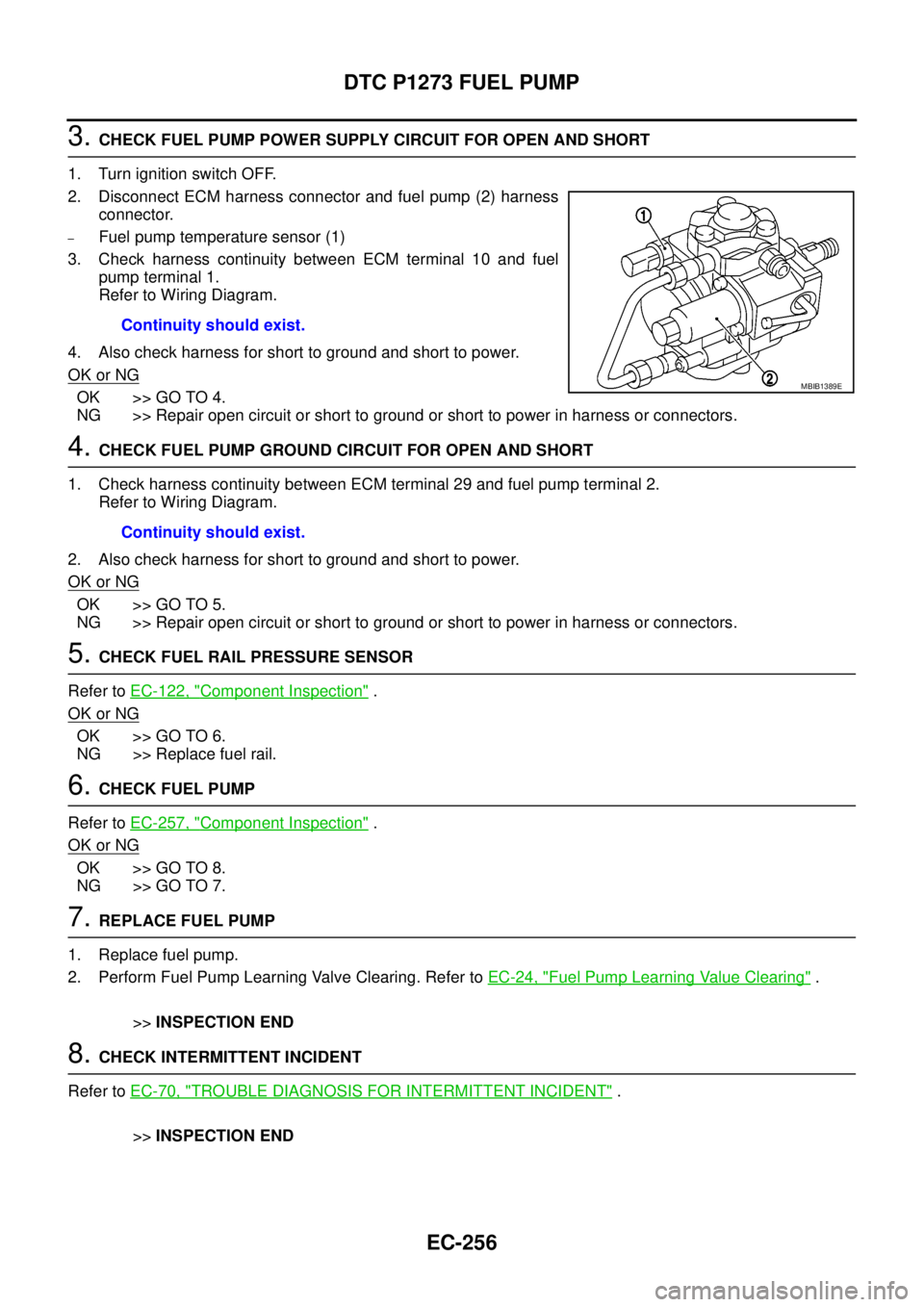
2. Disconnect ECM harness connector and fuel pump (2) harness
connector.
–Fuel pump temperature sensor (1)
3. Check harness continuity between ECM terminal 10 and fuel
pump terminal 1.
Refer to Wiring Diagram.
4. Also check harness for short to ground and short to power.
OK or NG
OK >> GO TO 4.
NG >> Repair open circuit or short to ground or short to power in harness or connectors.
4.CHECK FUEL PUMP GROUND CIRCUIT FOR OPEN AND SHORT
1. Check harness continuity between ECM terminal 29 and fuel pump terminal 2.
Refer to Wiring Diagram.
2. Also check harness for short to ground and short to power.
OK or NG
OK >> GO TO 5.
NG >> Repair open circuit or short to ground or short to power in harness or connectors.
5.CHECK FUEL RAIL PRESSURE SENSOR
Refer toEC-122, "
Component Inspection".
OK or NG
OK >> GO TO 6.
NG >> Replace fuel rail.
6.CHECK FUEL PUMP
Refer toEC-257, "
Component Inspection".
OK or NG
OK >> GO TO 8.
NG >> GO TO 7.
7.REPLACE FUEL PUMP
1. Replace fuel pump.
2. Perform Fuel Pump Learning Valve Clearing. Refer toEC-24, "
Fuel Pump Learning Value Clearing".
>>INSPECTION END
8.CHECK INTERMITTENT INCIDENT
Refer toEC-70, "
TROUBLE DIAGNOSIS FOR INTERMITTENT INCIDENT".
>>INSPECTION END Continuity should exist.
MBIB1389E
Continuity should exist.
Page 1239 of 3171
DTC P1274 FUEL PUMP
EC-259
C
D
E
F
G
H
I
J
K
L
MA
EC
: Average voltage for pulse signal (Actual pulse signal can be confirmed by oscilloscope.)
On Board Diagnosis LogicEBS01KK2
NOTE:
If DTC P1274 is displayed with DTC P0652 or P0653, first perform the trouble diagnosis for DTC P0652
or P0653. Refer toEC-227, "
DTC P0652, P0653 SENSOR POWER SUPPLY".
DTC Confirmation ProcedureEBS01KK3
NOTE:
If DTC Confirmation Procedure has been previously conducted, always turn ignition switch OFF and wait at
least 10 seconds before conducting the next test.
WITH CONSULT-II
1. Tuning ignition switch ON.
2. Select “DATA MONITOR” mode with CONSULT-II.
3. Start engine and let idle for at least 5 seconds.
4. If DTC is detected, go toEC-261, "
Diagnostic Procedure".
WITHOUT CONSULT-II
1. Start engine and let idle for at least 5 seconds.
2. Turn ignition switch OFF, wait at least 10 seconds and then turn ON.
3. Perform Diagnostic Test Mode II (Self-diagnostic results) with ECM.
4. If DTC is detected, go toEC-261, "
Diagnostic Procedure".
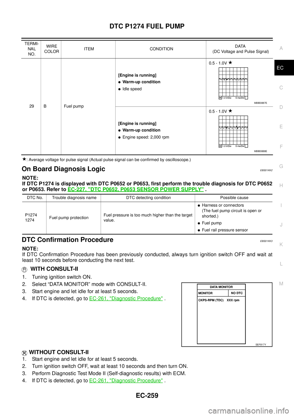
29 B Fuel pump[Engine is running]
lWarm-up condition
lIdle speed0.5 - 1.0V
[Engine is running]
lWarm-up condition
lEngine speed: 2,000 rpm0.5 - 1.0V TERMI-
NAL
NO.WIRE
COLORITEM CONDITIONDATA
(DC Voltage and Pulse Signal)
MBIB0887E
MBIB0888E
DTC No. Trouble diagnosis name DTC detecting condition Possible cause
P1274
1274Fuel pump protectionFuel pressure is too much higher than the target
value.
lHarness or connectors
(The fuel pump circuit is open or
shorted.)
lFuel pump
lFuel rail pressure sensor
SEF817Y
Page 1241 of 3171
DTC P1274 FUEL PUMP
EC-261
C
D
E
F
G
H
I
J
K
L
MA
EC
Diagnostic ProcedureEBS01KK5
1.CHECK ECM OUTPUT SIGNAL CIRCUIT FOR OPEN AND SHORT
1. Turn ignition switch OFF.
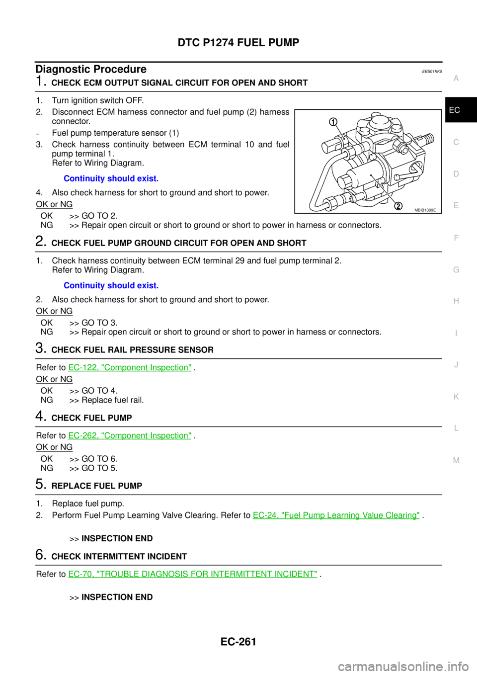
2. Disconnect ECM harness connector and fuel pump (2) harness
connector.
–Fuel pump temperature sensor (1)
3. Check harness continuity between ECM terminal 10 and fuel
pump terminal 1.
Refer to Wiring Diagram.
4. Also check harness for short to ground and short to power.
OK or NG
OK >> GO TO 2.
NG >> Repair open circuit or short to ground or short to power in harness or connectors.
2.CHECK FUEL PUMP GROUND CIRCUIT FOR OPEN AND SHORT
1. Check harness continuity between ECM terminal 29 and fuel pump terminal 2.
Refer to Wiring Diagram.
2. Also check harness for short to ground and short to power.
OK or NG
OK >> GO TO 3.
NG >> Repair open circuit or short to ground or short to power in harness or connectors.
3.CHECK FUEL RAIL PRESSURE SENSOR
Refer toEC-122, "
Component Inspection".
OK or NG
OK >> GO TO 4.
NG >> Replace fuel rail.
4.CHECK FUEL PUMP
Refer toEC-262, "
Component Inspection".
OK or NG
OK >> GO TO 6.
NG >> GO TO 5.
5.REPLACE FUEL PUMP
1. Replace fuel pump.
2. Perform Fuel Pump Learning Valve Clearing. Refer toEC-24, "
Fuel Pump Learning Value Clearing".
>>INSPECTION END
6.CHECK INTERMITTENT INCIDENT
Refer toEC-70, "
TROUBLE DIAGNOSIS FOR INTERMITTENT INCIDENT".
>>INSPECTION END Continuity should exist.
MBIB1389E
Continuity should exist.
Page 1244 of 3171
EC-264
DTC P1275 FUEL PUMP
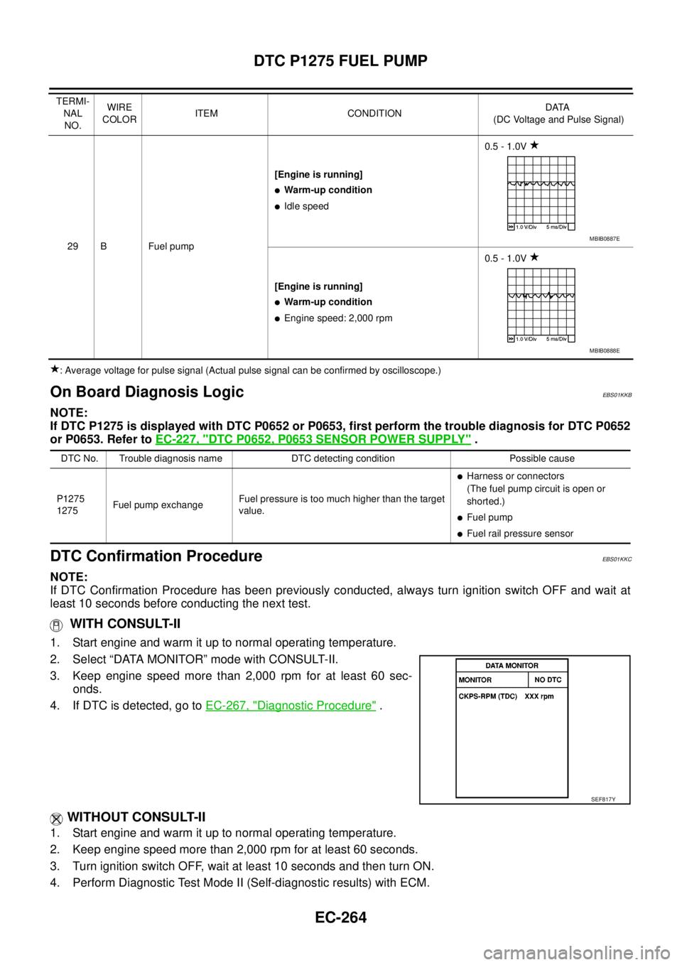
: Average voltage for pulse signal (Actual pulse signal can be confirmed by oscilloscope.)
On Board Diagnosis LogicEBS01KKB
NOTE:
If DTC P1275 is displayed with DTC P0652 or P0653, first perform the trouble diagnosis for DTC P0652
or P0653. Refer toEC-227, "
DTC P0652, P0653 SENSOR POWER SUPPLY".
DTC Confirmation ProcedureEBS01KKC
NOTE:
If DTC Confirmation Procedure has been previously conducted, always turn ignition switch OFF and wait at
least 10 seconds before conducting the next test.
WITH CONSULT-II
1. Start engine and warm it up to normal operating temperature.
2. Select “DATA MONITOR” mode with CONSULT-II.
3. Keep engine speed more than 2,000 rpm for at least 60 sec-
onds.
4. If DTC is detected, go toEC-267, "
Diagnostic Procedure".
WITHOUT CONSULT-II
1. Start engine and warm it up to normal operating temperature.
2. Keep engine speed more than 2,000 rpm for at least 60 seconds.
3. Turn ignition switch OFF, wait at least 10 seconds and then turn ON.
4. Perform Diagnostic Test Mode II (Self-diagnostic results) with ECM.
29 B Fuel pump[Engine is running]
lWarm-up condition
lIdle speed0.5 - 1.0V
[Engine is running]
lWarm-up condition
lEngine speed: 2,000 rpm0.5 - 1.0V TERMI-
NAL
NO.WIRE
COLORITEM CONDITIONDATA
(DC Voltage and Pulse Signal)
MBIB0887E
MBIB0888E
DTC No. Trouble diagnosis name DTC detecting condition Possible cause
P1275
1275Fuel pump exchangeFuel pressure is too much higher than the target
value.
lHarness or connectors
(The fuel pump circuit is open or
shorted.)
lFuel pump
lFuel rail pressure sensor
SEF817Y
Page 1247 of 3171
DTC P1275 FUEL PUMP
EC-267
C
D
E
F
G
H
I
J
K
L
MA
EC
Diagnostic ProcedureEBS01KKE
1.CHECK ECM OUTPUT SIGNAL CIRCUIT FOR OPEN AND SHORT
1. Turn ignition switch OFF.
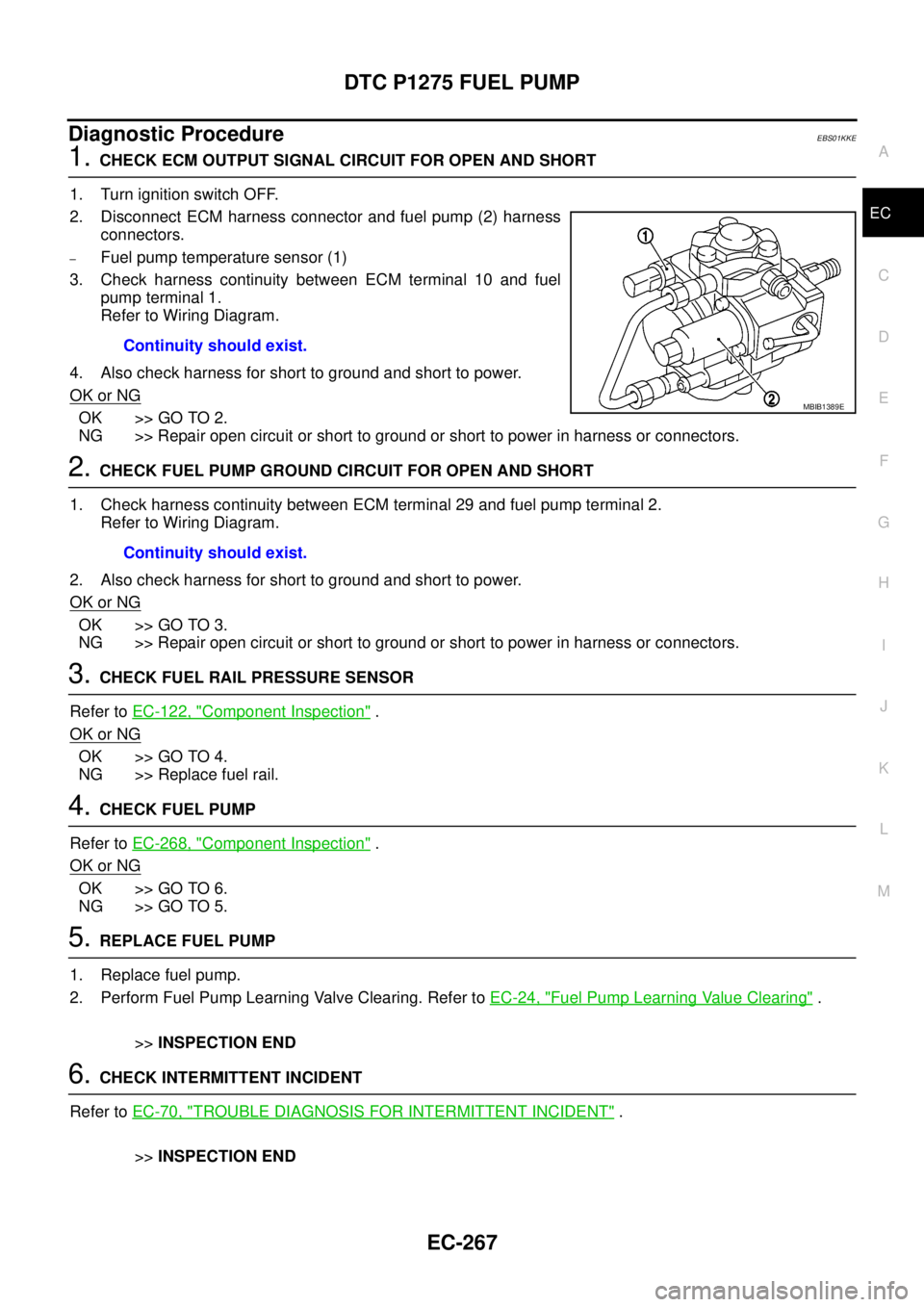
2. Disconnect ECM harness connector and fuel pump (2) harness
connectors.
–Fuel pump temperature sensor (1)
3. Check harness continuity between ECM terminal 10 and fuel
pump terminal 1.
Refer to Wiring Diagram.
4. Also check harness for short to ground and short to power.
OK or NG
OK >> GO TO 2.
NG >> Repair open circuit or short to ground or short to power in harness or connectors.
2.CHECK FUEL PUMP GROUND CIRCUIT FOR OPEN AND SHORT
1. Check harness continuity between ECM terminal 29 and fuel pump terminal 2.
Refer to Wiring Diagram.
2. Also check harness for short to ground and short to power.
OK or NG
OK >> GO TO 3.
NG >> Repair open circuit or short to ground or short to power in harness or connectors.
3.CHECK FUEL RAIL PRESSURE SENSOR
Refer toEC-122, "
Component Inspection".
OK or NG
OK >> GO TO 4.
NG >> Replace fuel rail.
4.CHECK FUEL PUMP
Refer toEC-268, "
Component Inspection".
OK or NG
OK >> GO TO 6.
NG >> GO TO 5.
5.REPLACE FUEL PUMP
1. Replace fuel pump.
2. Perform Fuel Pump Learning Valve Clearing. Refer toEC-24, "
Fuel Pump Learning Value Clearing".
>>INSPECTION END
6.CHECK INTERMITTENT INCIDENT
Refer toEC-70, "
TROUBLE DIAGNOSIS FOR INTERMITTENT INCIDENT".
>>INSPECTION END Continuity should exist.
MBIB1389E
Continuity should exist.
Page 1249 of 3171
DTC P1616 ECM
EC-269
C
D
E
F
G
H
I
J
K
L
MA
EC
DTC P1616 ECMPFP:23710
DescriptionEBS01KKH
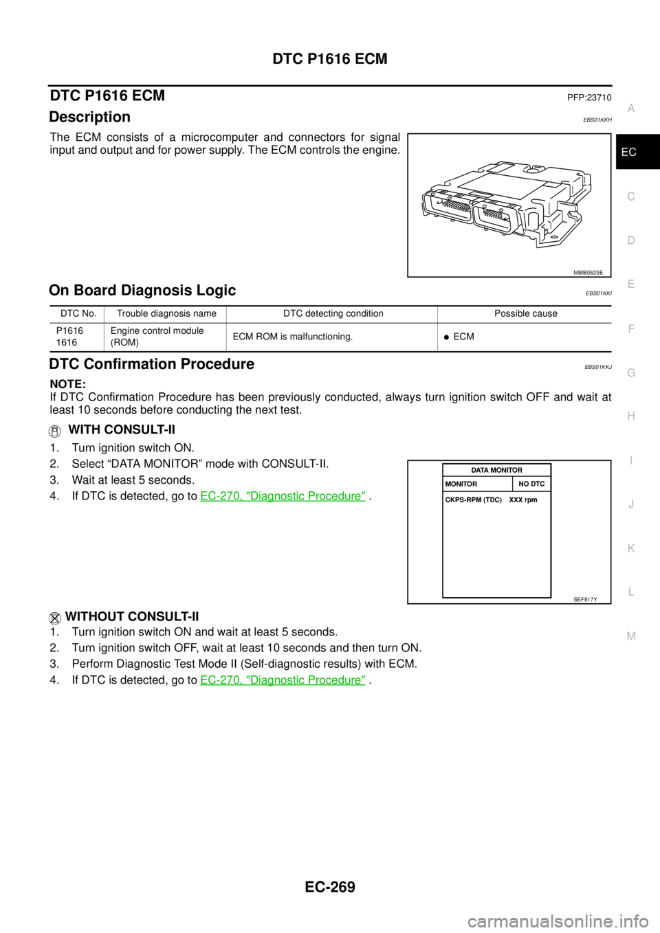
The ECM consists of a microcomputer and connectors for signal
input and output and for power supply. The ECM controls the engine.
On Board Diagnosis LogicEBS01KKI
DTC Confirmation ProcedureEBS01KKJ
NOTE:
If DTC Confirmation Procedure has been previously conducted, always turn ignition switch OFF and wait at
least 10 seconds before conducting the next test.
WITH CONSULT-II
1. Turn ignition switch ON.
2. Select “DATA MONITOR” mode with CONSULT-II.
3. Wait at least 5 seconds.
4. If DTC is detected, go toEC-270, "
Diagnostic Procedure".
WITHOUT CONSULT-II
1. Turn ignition switch ON and wait at least 5 seconds.
2. Turn ignition switch OFF, wait at least 10 seconds and then turn ON.
3. Perform Diagnostic Test Mode II (Self-diagnostic results) with ECM.
4. If DTC is detected, go toEC-270, "
Diagnostic Procedure".
MBIB0625E
DTC No. Trouble diagnosis name DTC detecting condition Possible cause
P1616
1616Engine control module
(ROM)ECM ROM is malfunctioning.
lECM
SEF817Y
Page 1250 of 3171
EC-270
DTC P1616 ECM
Diagnostic Procedure
EBS01KKK
1.INSPECTION START
With CONSULT-II
1. Turn ignition switch ON.
2. Select “SELF DIAG RESULTS” mode with CONSULT-II.
3. Touch “ERASE”.
4. PerformEC-269, "
DTC Confirmation Procedure",again.
5. Is DTC P1616 displayed again?
Without CONSULT-II
1. Turn ignition switch ON.
2. Erase the Diagnostic Test Mode II (Self-diagnostic results) memory. Refer toEC-27
.
3. PerformEC-269, "
DTC Confirmation Procedure",again.
4. Is DTC 1616 displayed again?
Ye s o r N o
Yes >>GOTO2.
No >>INSPECTION END
2.REPLACE ECM
1. Replace ECM.
2. Perform initialization of NATS system and registration of all NATS ignition key IDs. Refer toBL-172, "
ECM
Re-communicating Function".
3. Perform Fuel Pump Learning Value Clearing. Refer toEC-24, "
Fuel Pump Learning Value Clearing".
4. Perform Injector Adjustment Value Registration. Refer toEC-25, "
Injector Adjustment Value Registration".
>>INSPECTION END