Page 1189 of 3171
DTC P0580, P0581 ASCD STEERING SWITCH
EC-209
C
D
E
F
G
H
I
J
K
L
MA
EC
Diagnostic ProcedureEBS01KIA
1.CHECK GROUND CONNECTIONS
1. Turn ignition switch OFF.
2. Loosen and retighten three ground screws on the body.
Refer toEC-78, "
Ground Inspection".
OK or NG
OK >> GO TO 2.
NG >> Repair or replace ground connections.
: Vehicle front
1. Body ground E21 2. ECM 3. Body ground E41
4. A/C high-pressure service valve 5. ABS actuator and electric unit
(control unit)6. Body ground E61
MBIB1218E
Page 1190 of 3171

EC-210
DTC P0580, P0581 ASCD STEERING SWITCH
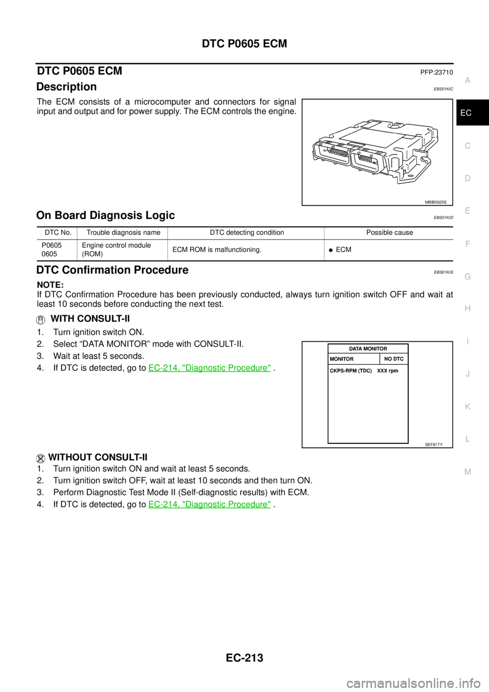
2.CHECK ASCD STEERING SWITCH CIRCUIT
With CONSULT-II
1. Turn ignition switch ON.
2. Select “MAIN SW”, “RESUME/ACC SW”, “SET SW” and “CANCEL SW” in “DATA MONITOR” mode with
CONSULT-II.
3. Check each item indication under the following conditions.
Without CONSULT-II
1. Turn ignition switch ON.
2. Check voltage between ECM terminal 102 and ground with
pressing each button.
OK or NG
OK >> GO TO 8.
NG >> GO TO 3.
3.CHECK ASCD STEERING SWITCH GROUND CIRCUIT FOR OPEN AND SHORT
1. Turn ignition switch OFF.
2. Disconnect combination switch harness connector.
3. Disconnect ECM harness connector.
4. Check harness continuity between combination switch terminal 17 and ECM terminal 103. Refer to Wiring
Diagram.
5. Also check harness for short to ground and short to power.
OK or NG
OK >> GO TO 5.
NG >> GO TO 4.
Switch Monitor item Condition Indication
MAIN switch MAIN SWPressed ON
Released OFF
CANCEL switch CANCEL SWPressed ON
Released OFF
RESUME/ACCELERATE
switchRESUME/ACC SWPressed ON
Released OFF
SET/COAST switch SET SWPressed ON
Released OFF
SEC006D
Switch Condition Voltage [V]
MAIN switchPressed Approx. 0
Released Approx. 4.3
CANCEL switchPressed Approx. 1.3
Released Approx. 4.3
RESUME/ACCELERATE
switchPressed Approx. 3.3
Released Approx. 4.3
SET/COAST switchPressed Approx. 2.3
Released Approx. 4.3
MBIB0043E
Continuity should exist.
Page 1193 of 3171

DTC P0605 ECM
EC-213
C
D
E
F
G
H
I
J
K
L
MA
EC
DTC P0605 ECMPFP:23710
DescriptionEBS01KIC
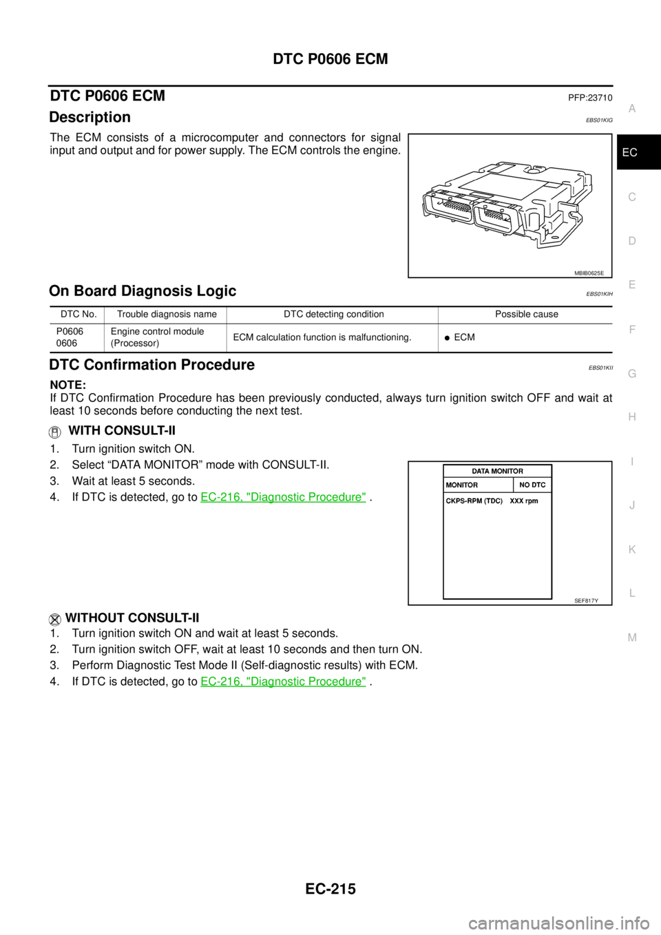
The ECM consists of a microcomputer and connectors for signal
input and output and for power supply. The ECM controls the engine.
On Board Diagnosis LogicEBS01KID
DTC Confirmation ProcedureEBS01KIE
NOTE:
If DTC Confirmation Procedure has been previously conducted, always turn ignition switch OFF and wait at
least 10 seconds before conducting the next test.
WITH CONSULT-II
1. Turn ignition switch ON.
2. Select “DATA MONITOR” mode with CONSULT-II.
3. Wait at least 5 seconds.
4. If DTC is detected, go toEC-214, "
Diagnostic Procedure".
WITHOUT CONSULT-II
1. Turn ignition switch ON and wait at least 5 seconds.
2. Turn ignition switch OFF, wait at least 10 seconds and then turn ON.
3. Perform Diagnostic Test Mode II (Self-diagnostic results) with ECM.
4. If DTC is detected, go toEC-214, "
Diagnostic Procedure".
MBIB0625E
DTC No. Trouble diagnosis name DTC detecting condition Possible cause
P0605
0605Engine control module
(ROM)ECM ROM is malfunctioning.
lECM
SEF817Y
Page 1194 of 3171
EC-214
DTC P0605 ECM
Diagnostic Procedure
EBS01KIF
1.INSPECTION START
With CONSULT-II
1. Turn ignition switch ON.
2. Select “SELF DIAG RESULTS” mode with CONSULT-II.
3. Touch “ERASE”.
4. PerformEC-213, "
DTC Confirmation Procedure",again.
5. Is DTC P0605 displayed again?
Without CONSULT-II
1. Turn ignition switch ON.
2. Erase the Diagnostic Test Mode II (Self-diagnostic results) memory. Refer toEC-27
.
3. PerformEC-213, "
DTC Confirmation Procedure",again.
4. Is DTC 0605 displayed again?
Ye s o r N o
Yes >>GOTO2.
No >>INSPECTION END
2.REPLACE ECM
1. Replace ECM.
2. Perform initialization of NATS system and registration of all NATS ignition key IDs. Refer toBL-172, "
ECM
Re-communicating Function".
3. Perform Fuel Pump Learning Value Clearing. Refer toEC-24, "
Fuel Pump Learning Value Clearing".
4. Perform Injector Adjustment Value Registration. Refer toEC-25, "
Injector Adjustment Value Registration".
>>INSPECTION END
Page 1195 of 3171

DTC P0606 ECM
EC-215
C
D
E
F
G
H
I
J
K
L
MA
EC
DTC P0606 ECMPFP:23710
DescriptionEBS01KIG
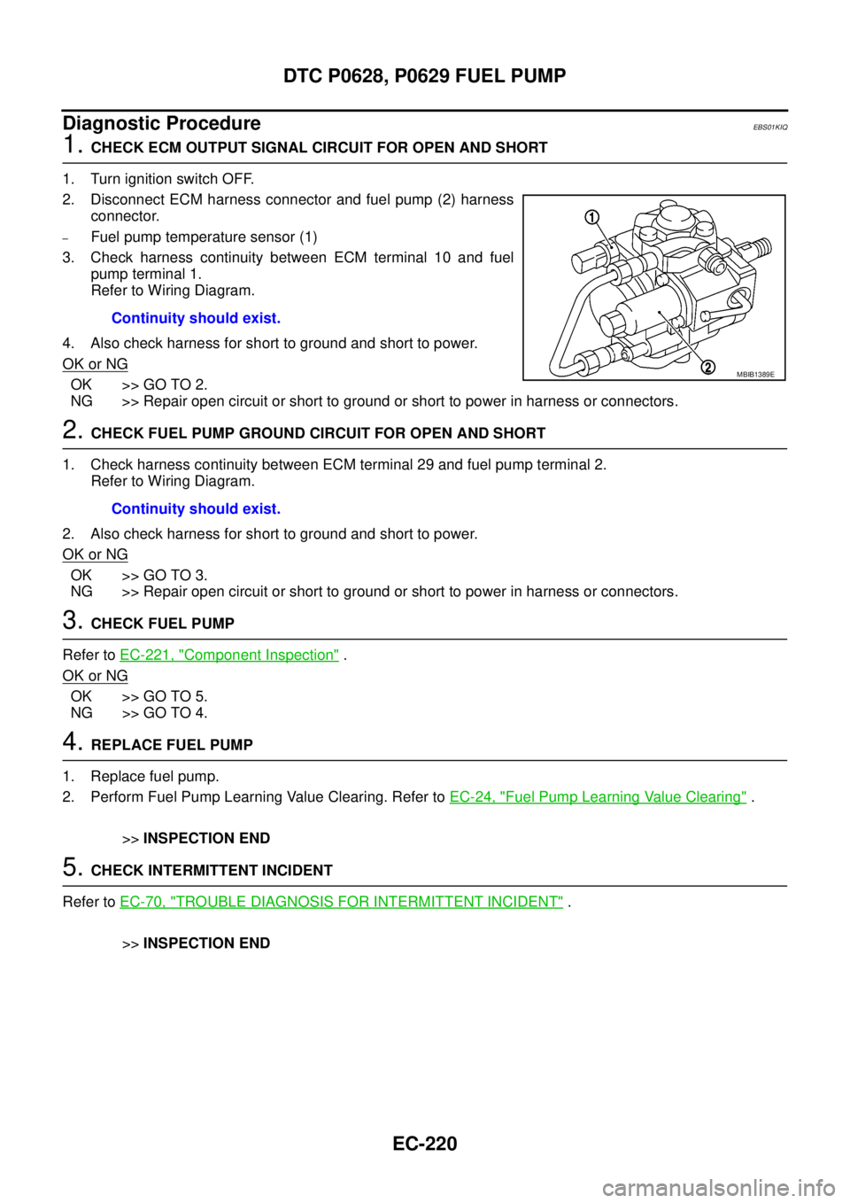
The ECM consists of a microcomputer and connectors for signal
input and output and for power supply. The ECM controls the engine.
On Board Diagnosis LogicEBS01KIH
DTC Confirmation ProcedureEBS01KII
NOTE:
If DTC Confirmation Procedure has been previously conducted, always turn ignition switch OFF and wait at
least 10 seconds before conducting the next test.
WITH CONSULT-II
1. Turn ignition switch ON.
2. Select “DATA MONITOR” mode with CONSULT-II.
3. Wait at least 5 seconds.
4. If DTC is detected, go toEC-216, "
Diagnostic Procedure".
WITHOUT CONSULT-II
1. Turn ignition switch ON and wait at least 5 seconds.
2. Turn ignition switch OFF, wait at least 10 seconds and then turn ON.
3. Perform Diagnostic Test Mode II (Self-diagnostic results) with ECM.
4. If DTC is detected, go toEC-216, "
Diagnostic Procedure".
MBIB0625E
DTC No. Trouble diagnosis name DTC detecting condition Possible cause
P0606
0606Engine control module
(Processor)ECM calculation function is malfunctioning.
lECM
SEF817Y
Page 1196 of 3171
EC-216
DTC P0606 ECM
Diagnostic Procedure
EBS01KIJ
1.INSPECTION START
With CONSULT-II
1. Turn ignition switch ON.
2. Select “SELF DIAG RESULTS” mode with CONSULT-II.
3. Touch “ERASE”.
4. PerformEC-215, "
DTC Confirmation Procedure",again.
5. Is DTC P0606 displayed again?
Without CONSULT-II
1. Turn ignition switch ON.
2. Erase the Diagnostic Test Mode II (Self-diagnostic results) memory. Refer toEC-27
.
3. PerformEC-215, "
DTC Confirmation Procedure",again.
4. Is DTC 0606 displayed again?
Ye s o r N o
Yes >>GOTO2.
No >>INSPECTION END
2.REPLACE ECM
1. Replace ECM.
2. Perform initialization of NATS system and registration of all NATS ignition key IDs. Refer toBL-172, "
ECM
Re-communicating Function".
3. Perform Fuel Pump Learning Value Clearing. Refer toEC-24, "
Fuel Pump Learning Value Clearing".
4. Perform Injector Adjustment Value Registration. Refer toEC-25, "
Injector Adjustment Value Registration".
>>INSPECTION END
Page 1198 of 3171

EC-218
DTC P0628, P0629 FUEL PUMP
: Average voltage for pulse signal (Actual pulse signal can be confirmed by oscilloscope.)
On Board Diagnosis LogicEBS01KIN
DTC Confirmation ProcedureEBS01KIO
NOTE:
If DTC Confirmation Procedure has been previously conducted, always turn ignition switch OFF and wait at
least 10 seconds before conducting the next test.
WITH CONSULT-II
1. Start engine and warm it up to normal operating temperature.
2. Select “DATA MONITOR” mode with CONSULT-II.
3. Let engine idle for at least 5 seconds.
4. If DTC is detected, go toEC-220, "
Diagnostic Procedure".
WITHOUT CONSULT-II
1. Start engine and warm it up to normal operating temperature.
2. Let engine idle for at least 5 seconds.
3. Turn ignition switch OFF, wait at least 10 seconds and then turn ON.
4. Perform Diagnostic Test Mode II (Self-diagnostic results) with ECM.
5. If DTC is detected, go toEC-220, "
Diagnostic Procedure".
29 B Fuel pump[Engine is running]
lWarm-up condition
lIdle speed0.5 - 1.0V
[Engine is running]
lWarm-up condition
lEngine speed: 2,000 rpm0.5 - 1.0V TERMI-
NAL
NO.WIRE
COLORITEM CONDITIONDATA
(DC Voltage and Pulse Signal)
MBIB0887E
MBIB0888E
DTC No. Trouble diagnosis name DTC detecting condition Possible cause
P0628
0628Fuel pump control circuit
low inputECM detects a control circuit for the fuel pump is
open or short to ground.
lHarness or connectors
(The fuel pump circuit is open or
shorted.)
lFuel pump P0629
0629Fuel pump control circuit
high outputECM detects a control circuit for the fuel pump is
short to power.
SEF817Y
Page 1200 of 3171

EC-220
DTC P0628, P0629 FUEL PUMP
Diagnostic Procedure
EBS01KIQ
1.CHECK ECM OUTPUT SIGNAL CIRCUIT FOR OPEN AND SHORT
1. Turn ignition switch OFF.
2. Disconnect ECM harness connector and fuel pump (2) harness
connector.
–Fuel pump temperature sensor (1)
3. Check harness continuity between ECM terminal 10 and fuel
pump terminal 1.
Refer to Wiring Diagram.
4. Also check harness for short to ground and short to power.
OK or NG
OK >> GO TO 2.
NG >> Repair open circuit or short to ground or short to power in harness or connectors.
2.CHECK FUEL PUMP GROUND CIRCUIT FOR OPEN AND SHORT
1. Check harness continuity between ECM terminal 29 and fuel pump terminal 2.
Refer to Wiring Diagram.
2. Also check harness for short to ground and short to power.
OK or NG
OK >> GO TO 3.
NG >> Repair open circuit or short to ground or short to power in harness or connectors.
3.CHECK FUEL PUMP
Refer toEC-221, "
Component Inspection".
OK or NG
OK >> GO TO 5.
NG >> GO TO 4.
4.REPLACE FUEL PUMP
1. Replace fuel pump.
2. Perform Fuel Pump Learning Value Clearing. Refer toEC-24, "
Fuel Pump Learning Value Clearing".
>>INSPECTION END
5.CHECK INTERMITTENT INCIDENT
Refer toEC-70, "
TROUBLE DIAGNOSIS FOR INTERMITTENT INCIDENT".
>>INSPECTION END Continuity should exist.
MBIB1389E
Continuity should exist.