Page 1000 of 3171

EC-20
ENGINE CONTROL SYSTEM
MAXIMUM AMOUNT CONTROL
Input/Output Signal Chart
The maximum injection amount is controlled to an optimum by the engine speed, intake air amount, engine
coolant temperature, and accelerator opening in accordance with the driving conditions.
This prevents the oversupply of the injection amount caused by decreased air density at a high altitude or dur-
ing a system failure.
DECELERATION CONTROL
Input/Output Signal Chart
The ECM sends a fuel cut signal to the fuel injectors and fuel pump during deceleration for better fuel effi-
ciency. The ECM determines the time of deceleration according to signals from the accelerator pedal position
sensor and crankshaft position sensor.
Fuel Injection Timing Control SystemEBS01KCF
DESCRIPTION
The target fuel injection timing in accordance with the engine speed and the fuel injection amount are recorded
as a map in the ECM beforehand. The ECM determines the optimum injection timing using sensor signals
accordance with the map.
Air Conditioning Cut ControlEBS01KCG
INPUT / OUTPUT SIGNAL CHART
*1: The input signal is sent to the ECM through CAN communication line.
*2: The output signal is sent from the ECM through CAN communication line.
SYSTEM DESCRIPTION
This system improves acceleration when the air conditioner is used.
When the accelerator pedal is fully depressed, the air conditioner is turned off for a few seconds.
When engine coolant temperature becomes excessively high, the air conditioner is turned off. This continues
until the engine coolant temperature returns to normal.
Fuel Cut Control (At No Load & High Engine Speed)EBS01KCH
INPUT/OUTPUT SIGNAL CHART
*: The input signal is sent to the ECM through CAN communication line.Sensor Input Signal to ECM ECM Function Actuator
Mass air flow sensor Amount of intake air
Fuel injection
control (maxi-
mum amount
control)Fuel injector Engine coolant temperature sensor Engine coolant temperature
Crankshaft position sensor Engine speed
Accelerator pedal position sensor Accelerator pedal position
Sensor Input Signal to ECM ECM Function Actuator
Accelerator pedal position sensor Accelerator pedal position Fuel injection
control (decel-
eration control)Fuel injector
Fuel pump
Crankshaft position sensor Engine speed
Sensor Input Signal to ECM ECM Function Actuator
Air conditioner switch
Air conditioner ON signal*
1
Air conditioner
cut controlAir conditioner relay*2
Accelerator pedal position sensor Accelerator pedal opening angle
Wheel sensor
Vehicle speed*
1
Engine coolant temperature sensor Engine coolant temperature
Refrigerant pressure sensor Refrigerant pressure
Sensor Input Signal to ECM ECM Function Actuator
Wheel sensor Vehicle speed*
Fuel cut control Fuel injector Accelerator pedal position sensor Accelerator pedal position
Crankshaft position sensor Engine speed
Page 1008 of 3171

EC-28
ON BOARD DIAGNOSTIC (OBD) SYSTEM
lIf the battery is disconnected, the emission-related diagnostic information will be lost within 24
hours.
lThe following data are cleared when the ECM memory is erased.
–Diagnostic trouble codes
–Freeze frame data
–Fuel pump learning value
Actual work procedures are explained using a DTC as an example. Be careful so that not only the DTC, but all
of the data listed above, are cleared from the ECM memory during work procedures.
Freeze Frame DataEBS01KCP
The ECM records the driving conditions such as calculated load value, engine coolant temperature, engine
speed, vehicle speed and intake manifold pressure at the moment a malfunction is detected.
The data, stored together with the DTC data, are called freeze frame data and displayed on CONSULT-II. For
details, seeEC-28, "
Freeze Frame Data".
Only one set of freeze frame data can be stored in the ECM. If freeze frame data is stored in the ECM memory
and another freeze frame data occurs later, the first (original) freeze frame data remains unchanged in the
ECM memory.
Freeze frame data (along with the DTCs) are cleared when the ECM memory is erased. Procedures for clear-
ing the ECM memory are described inEC-27, "
HOW TO ERASE DTC".
NATS (Nissan Anti-theft System)EBS01KCQ
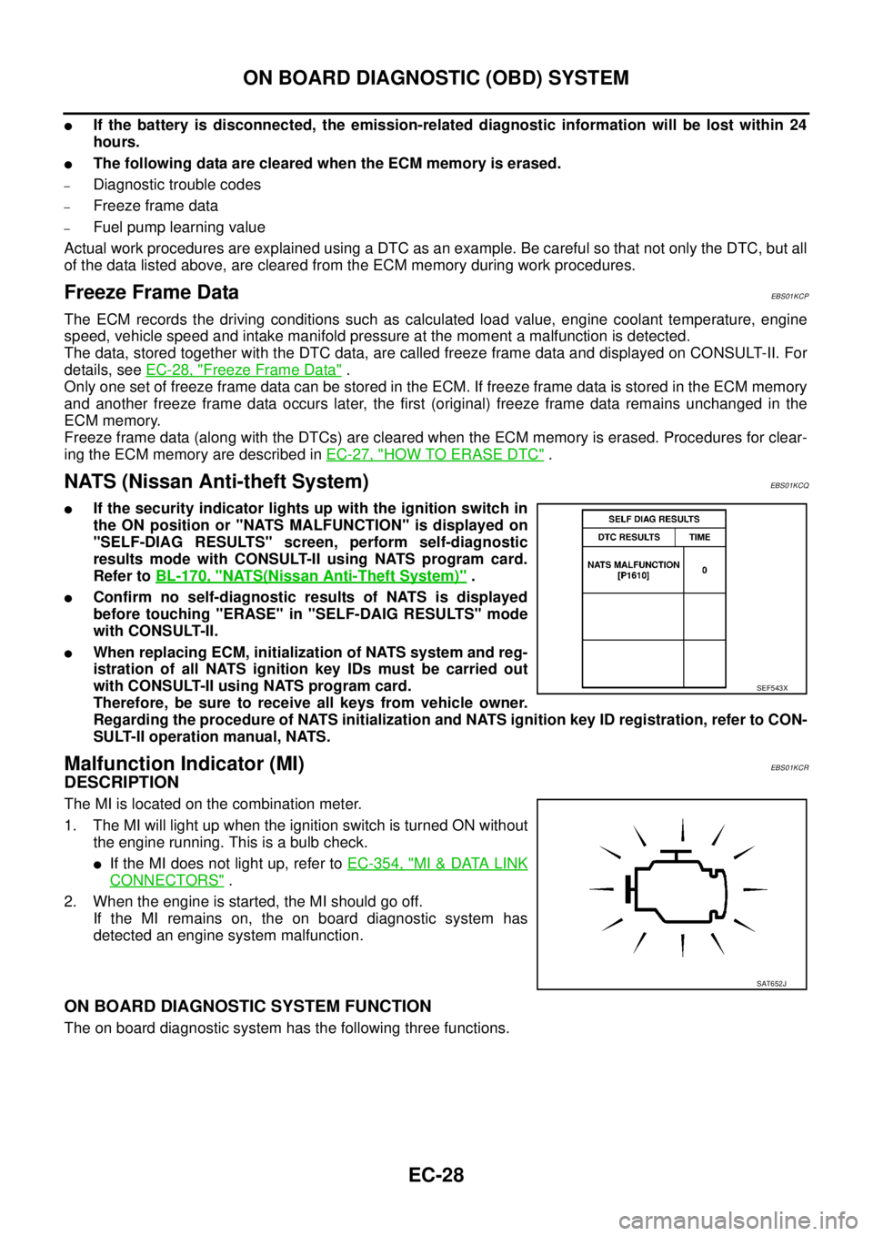
lIf the security indicator lights up with the ignition switch in
the ON position or "NATS MALFUNCTION" is displayed on
"SELF-DIAG RESULTS" screen, perform self-diagnostic
results mode with CONSULT-II using NATS program card.
Refer toBL-170, "
NATS(Nissan Anti-Theft System)".
lConfirm no self-diagnostic results of NATS is displayed
before touching "ERASE" in "SELF-DAIG RESULTS" mode
with CONSULT-II.
lWhen replacing ECM, initialization of NATS system and reg-
istration of all NATS ignition key IDs must be carried out
with CONSULT-II using NATS program card.
Therefore, be sure to receive all keys from vehicle owner.
Regarding the procedure of NATS initialization and NATS ignition key ID registration, refer to CON-
SULT-II operation manual, NATS.
Malfunction Indicator (MI)EBS01KCR
DESCRIPTION
The MI is located on the combination meter.
1. The MI will light up when the ignition switch is turned ON without
the engine running. This is a bulb check.
lIf the MI does not light up, refer toEC-354, "MI&DATA LINK
CONNECTORS".
2. When the engine is started, the MI should go off.
If the MI remains on, the on board diagnostic system has
detected an engine system malfunction.
ON BOARD DIAGNOSTIC SYSTEM FUNCTION
The on board diagnostic system has the following three functions.
SEF543X
SAT652J
Page 1017 of 3171

TROUBLE DIAGNOSIS
EC-37
C
D
E
F
G
H
I
J
K
L
MA
EC
DTC Inspection Priority ChartEBS01KCU
If some DTCs are displayed at the same time, perform inspections one by one based on the following priority
chart.
NOTE:
If DTC U1000 is displayed with other DTC, first perform the trouble diagnosis for DTC U1000. Refer to
EC-79, "
DTC U1000 CAN COMMUNICATION LINE".
Priority Detected items (DTC)
1
lU1000 CAN communication line
lP0016 Crankshaft position - camshaft position correlation
lP0102 P0103 Mass air flow sensor
lP0112 P0113 Intake air temperature sensor
lP0117 P0118 Engine coolant temperature sensor
lP0122 P0123 P0222 P0223 P2135 Accelerator pedal position sensor
lP0182 P0183 Fuel pump temperature sensor
lP0192 P0193 Fuel rail pressure sensor
lP0237 P0238 Turbocharger boost sensor
lP0335 P0336 Crankshaft position sensor
lP0340 P0341 Camshaft position sensor
lP0563 Battery voltage
lP0605 P0606 P1616 ECM
lP0642 P0643 P0652 P0653 Sensor power supply
lP1610 - P1615 NATS
lP1622 P1623 Injector adjustment value
lP2228 P2229 Barometric pressure sensor
2
lP0089 P0628 P0629 P1272 - P1275 Fuel pump
lP0200 - P0204 P1268 - P1271 P2146 - P2149 Fuel injector
lP0686 ECM relay
3
lP0088 P0093 Fuel system
lP0217 Engine over temperature (OVERHEAT)
lP0234 Turbocharger system
lP0501 P0502 P0503 ASCD vehicle speed sensor
lP0504 ASCD brake switch
lP0580 P0581 ASCD steering switch
Page 1022 of 3171

EC-42
TROUBLE DIAGNOSIS
Symptom Matrix Chart
EBS01KCW
SYSTEM — Basic engine control systemSYMPTOM
Reference
pageHARD/NO START/RESTART (EXCP. HA)
ENGINE STALL
HESITATION/SURGING/FLAT SPOT
KNOCK/DETONATION
LACK OF POWER
POOR ACCELERATION
HI IDLE
LOW IDLE NO START (with first firing)
NO START (without first firing)
HARD TO START WHEN ENGINE IS COLD
HARD TO START WHEN ENGINE IS HOT
AT I D L E
DURING DRIVING
WHEN DECELERATING
Warranty symptom code AA AB AC AD AE AF
Fuelpump 55555555 55 5 —
Fuelinjector 3333333334433EC-125
Glow control system 1 1 1 1 1EC-295
Engine body 3 3 3 3 3 3 3 3 4 4 3EM-106
EGR system33EC-302
Air cleaner and duct33EM-15
Fuel rail pressure relief valve 3 3 3 3 3 3 3 3 3 3 3EC-88
ENGINE CONTROL
Fuelpumpcircuit 44444444 44 4EC-217
Fuelinjectorcircuit 1111111111111EC-125
Fuel injector adjustment value 1 1 1 1EC-25
Mass air flow sensor circuit 1 1 1EC-92
Engine coolant temperature circuit 1 1 1 1EC-103
Vehicle speed signal circuit1LAN-30
Accelerator pedal position sensor circuit 1 1 1EC-108
,
EC-142
,
EC-275
Fuel rail pressure sensor circuitEC-118
Page 1024 of 3171

EC-44
TROUBLE DIAGNOSIS
SYSTEM — Basic engine control systemSYMPTOM
Reference
page
ROUGH IDLE/HUNTING
IDLING VIBRATION
SLOW/NO RETURN TO IDLE
OVERHEAT/HIGH ENGINE COOLANT TEMPERATURE
EXCESSIVE FUEL CONSUMPTION
EXCESSIVE OIL CONSUMPTION
ABNORMAL SMOKE COLOR
DEAD BATTERY (UNDER CHARGE)
Malfunction indicator illuminates.
Can be detected by CONSULT-II?BLACK SMOKE
WHITE SMOKE
Warranty symptom code AG AH AJ AK AL AM AP HA
Fuel pump 5 5 5 5 1 1 —
Fuel injector 3 3 3 4 3 3 1 1EC-125
Glow control system1EC-295
Engine body 3 3 3 3 1 3EM-106
EGR system3EC-302
Air cleaner and duct3EM-15
Fuel rail pressure relief valve 3 3 3 3EC-88
ENGINE CONTROL
Fuel pump circuit 4 4 4 4 1 1EC-217
Fuel injector circuit 1 1 1 1 1 1 1 1EC-125
Fuel injector adjustment value 1 1 1 1 1 1EC-25
Mass air flow sensor circuit 1 1 1EC-92
Engine coolant temperature circuit 1 1 1 1 1EC-103
Vehicle speed signal circuit11LAN-30
Accelerator pedal position sensor circuit 1 1 1EC-108
,
EC-142
,
EC-275
Fuel rail pressure sensor circuit11EC-118
Page 1025 of 3171

TROUBLE DIAGNOSIS
EC-45
C
D
E
F
G
H
I
J
K
L
MA
EC
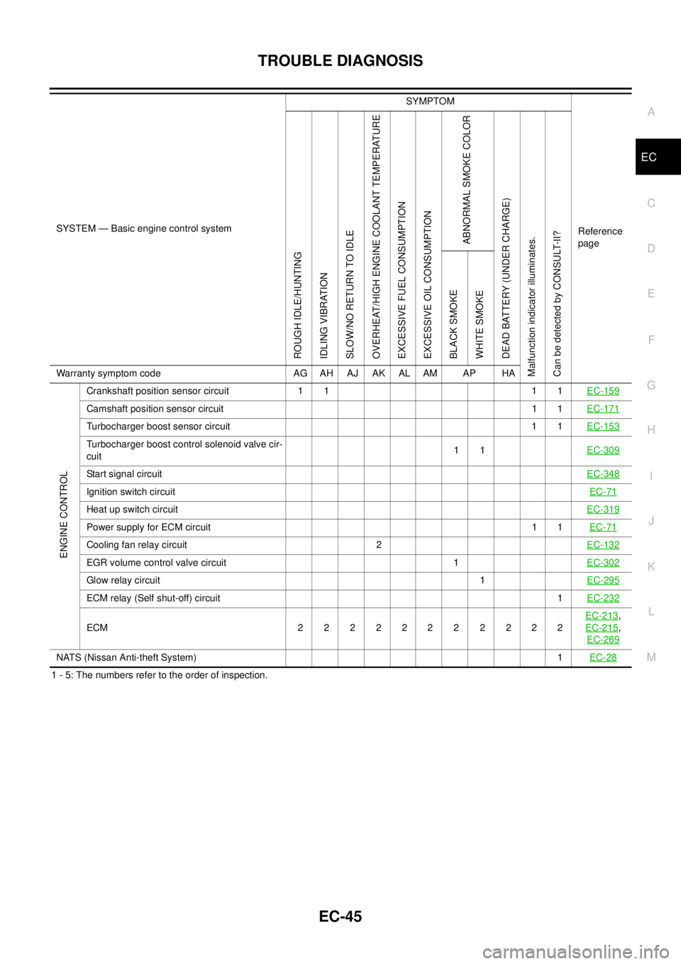
1 - 5: The numbers refer to the order of inspection.
ENGINE CONTROL
Crankshaft position sensor circuit 1 1 1 1EC-159
Camshaft position sensor circuit11EC-171
Turbocharger boost sensor circuit 1 1EC-153
Turbocharger boost control solenoid valve cir-
cuit11EC-309
Start signal circuitEC-348
Ignition switch circuitEC-71
Heat up switch circuitEC-319
Power supply for ECM circuit11EC-71
Cooling fan relay circuit 2EC-132
EGR volume control valve circuit 1EC-302
Glow relay circuit1EC-295
ECM relay (Self shut-off) circuit1EC-232
ECM 22 22222 2222EC-213
,
EC-215
,
EC-269
NATS (Nissan Anti-theft System)1EC-28
SYSTEM — Basic engine control systemSYMPTOM
Reference
page
ROUGH IDLE/HUNTING
IDLING VIBRATION
SLOW/NO RETURN TO IDLE
OVERHEAT/HIGH ENGINE COOLANT TEMPERATURE
EXCESSIVE FUEL CONSUMPTION
EXCESSIVE OIL CONSUMPTION
ABNORMAL SMOKE COLOR
DEAD BATTERY (UNDER CHARGE)
Malfunction indicator illuminates.
Can be detected by CONSULT-II?BLACK SMOKE
WHITE SMOKE
Warranty symptom code AG AH AJ AK AL AM AP HA
Page 1026 of 3171
EC-46
TROUBLE DIAGNOSIS
Engine Control Component Parts Location
EBS01KCX
1. IPDM E/R 2. ECM 3. Glow relay
4. Turbocharger boost sensor 5. Refrigerant pressure sensor 6. Engine coolant temperature sensor
7. Fuel pump 8. Cooling fan motor 9. Intake air control valve actuator
10. Turbocharger boost control solenoid
valve11. Mass air flow sensor 12. Turbocharger boost control actuator
13. Camshaft position sensor 14. Glow plug 15. Fuel injector
16. Fuel rail pressure sensor 17. Intake air control valve control
solenoid valve18. EGR volume control valve
MBIB1198E
Page 1027 of 3171
TROUBLE DIAGNOSIS
EC-47
C
D
E
F
G
H
I
J
K
L
MA
EC
: Vehicle front
1. Fuel pump temperature sensor 2. Fuel pump 3. Fuel rail pressure relief valve
4. Fuel rail 5. Engine coolant temperature sensor 6. EGR volume control valve
7. Fuel rail pressure sensor 8. Camshaft position sensor 9. Refrigerant pressure sensor
MBIB1388E