2005 NISSAN NAVARA Timing chain
[x] Cancel search: Timing chainPage 1476 of 3171
EM-94
CYLINDER HEAD
lRefer toGI-10, "Components"for symbol marks in the figure.
Removal and InstallationEBS01E6B
REMOVAL
1. Drain engine coolant. Refer toCO-7, "Changing Engine Coolant".
2. Remove the following:
lRocker cover (Refer toEM-56, "ROCKER COVER".)
lSpill tube and fuel injector (Refer toEM-44, "INJECTION TUBE AND FUEL INJECTOR".)
lIntake manifold (Refer toEM-20, "INTAKE MANIFOLD".)
lTurbocharger (Refer toEM-28, "TURBO CHARGER".)
lExhaust manifold (Refer toEM-34, "EXHAUST MANIFOLD".)
lSecondary timing chain (Refer toEM-73, "SECONDARY TIMING CHAIN".)
lCamshaft (Refer toEM-59, "CAMSHAFT".)
3. Remove cylinder head assembly.
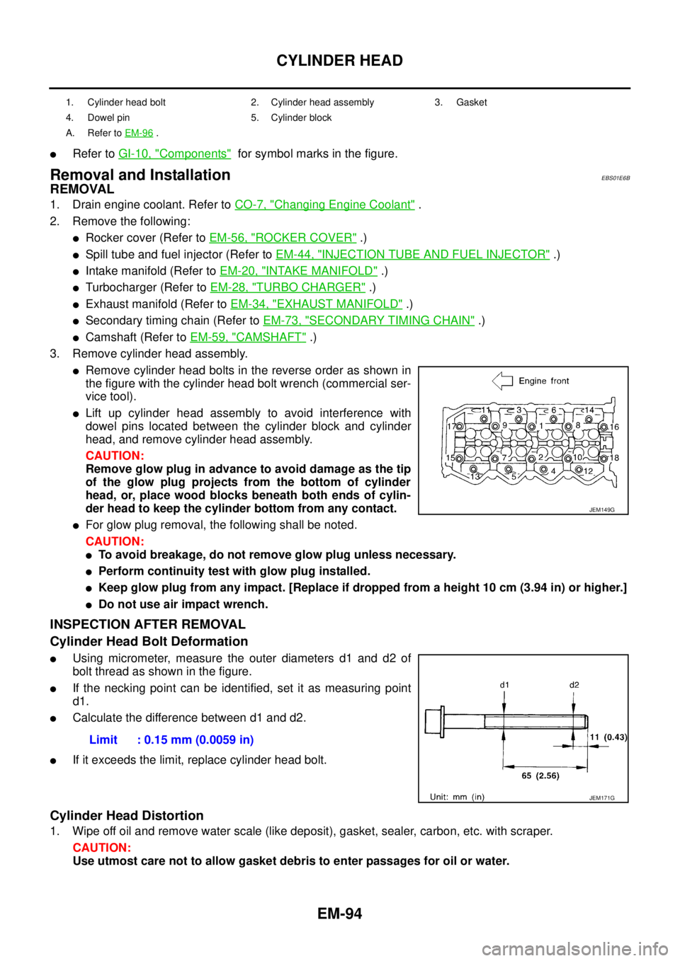
lRemove cylinder head bolts in the reverse order as shown in
the figure with the cylinder head bolt wrench (commercial ser-
vice tool).
lLift up cylinder head assembly to avoid interference with
dowel pins located between the cylinder block and cylinder
head, and remove cylinder head assembly.
CAUTION:
Remove glow plug in advance to avoid damage as the tip
of the glow plug projects from the bottom of cylinder
head, or, place wood blocks beneath both ends of cylin-
der head to keep the cylinder bottom from any contact.
lFor glow plug removal, the following shall be noted.
CAUTION:
lTo avoid breakage, do not remove glow plug unless necessary.
lPerform continuity test with glow plug installed.
lKeep glow plug from any impact. [Replace if dropped from a height 10 cm (3.94 in) or higher.]
lDo not use air impact wrench.
INSPECTION AFTER REMOVAL
Cylinder Head Bolt Deformation
lUsing micrometer, measure the outer diameters d1 and d2 of
bolt thread as shown in the figure.
lIf the necking point can be identified, set it as measuring point
d1.
lCalculate the difference between d1 and d2.
lIf it exceeds the limit, replace cylinder head bolt.
Cylinder Head Distortion
1. Wipe off oil and remove water scale (like deposit), gasket, sealer, carbon, etc. with scraper.
CAUTION:
Use utmost care not to allow gasket debris to enter passages for oil or water.
1. Cylinder head bolt 2. Cylinder head assembly 3. Gasket
4. Dowel pin 5. Cylinder block
A. Refer toEM-96
.
JEM149G
Limit : 0.15 mm (0.0059 in)
JEM171G
Page 1494 of 3171
EM-112
CYLINDER BLOCK
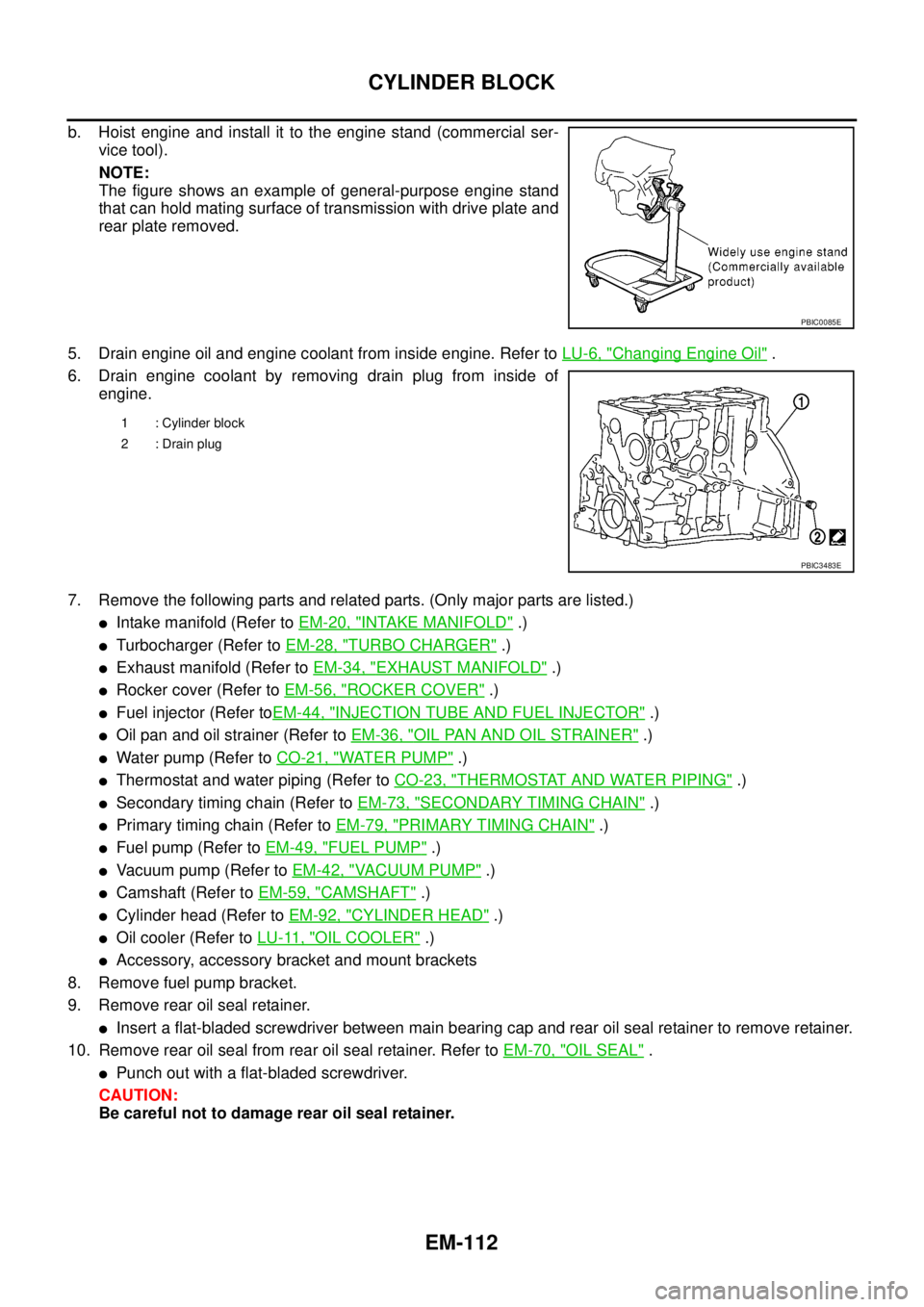
b. Hoist engine and install it to the engine stand (commercial ser-
vice tool).
NOTE:
The figure shows an example of general-purpose engine stand
that can hold mating surface of transmission with drive plate and
rear plate removed.
5. Drain engine oil and engine coolant from inside engine. Refer toLU-6, "
Changing Engine Oil".
6. Drain engine coolant by removing drain plug from inside of
engine.
7. Remove the following parts and related parts. (Only major parts are listed.)
lIntake manifold (Refer toEM-20, "INTAKE MANIFOLD".)
lTurbocharger (Refer toEM-28, "TURBO CHARGER".)
lExhaust manifold (Refer toEM-34, "EXHAUST MANIFOLD".)
lRocker cover (Refer toEM-56, "ROCKER COVER".)
lFuel injector (Refer toEM-44, "INJECTION TUBE AND FUEL INJECTOR".)
lOil pan and oil strainer (Refer toEM-36, "OIL PAN AND OIL STRAINER".)
lWater pump (Refer toCO-21, "WATER PUMP".)
lThermostat and water piping (Refer toCO-23, "THERMOSTAT AND WATER PIPING".)
lSecondary timing chain (Refer toEM-73, "SECONDARY TIMING CHAIN".)
lPrimary timing chain (Refer toEM-79, "PRIMARY TIMING CHAIN".)
lFuel pump (Refer toEM-49, "FUEL PUMP".)
lVacuum pump (Refer toEM-42, "VACUUM PUMP".)
lCamshaft (Refer toEM-59, "CAMSHAFT".)
lCylinder head (Refer toEM-92, "CYLINDER HEAD".)
lOil cooler (Refer toLU-11, "OIL COOLER".)
lAccessory, accessory bracket and mount brackets
8. Remove fuel pump bracket.
9. Remove rear oil seal retainer.
lInsert a flat-bladed screwdriver between main bearing cap and rear oil seal retainer to remove retainer.
10. Remove rear oil seal from rear oil seal retainer. Refer toEM-70, "
OIL SEAL".
lPunch out with a flat-bladed screwdriver.
CAUTION:
Be careful not to damage rear oil seal retainer.
PBIC0085E
1 : Cylinder block
2 : Drain plug
PBIC3483E
Page 1759 of 3171
IDX-7
A
C
D
E
F
G
H
I
J
K
L B
IDX
ALPHABETICAL INDEX
Starter ................................................................SC-27
Starting system ..................................................SC-27
Steering gear, linkage and transfer gear inspection .....
MA-36
,MA-37
Steering linkage .................................................PS-14
Steering wheel and column .................................PS-8
Step lamp .........................................................LT-145
Stop lamp .........................................................LT-121
Stop lamp switch .............................................EC-330
STOP/L - Wiring diagram .................................LT-121
Striking rod (M/T) ...............................................MT-23
Strut (front) ......................................................FSU-10
Sun roof, electric ................................................RF-10
Sunload sensor ..............................................ATC-112
Sunroof ..................................................RF-10,RF-21
Super lock ...........................................................BL-55
Supplemental Restraint System ........................SRS-6
Symbols and abbreviations .....................GI-10,GI-23
Symptom matrix chart ........................................EC-42
Synchronizer (M/T) ............................................MT-21
T
Tachometer ..........................................................DI-4
Tail lamp ...........................................................LT-125
TAIL/L - Wiring diagram ....................................LT-127
TC boost control solnoid valve ........................EC-309
TC boost sensor ..............................................EC-153
TCC/V - Wiring diagram ..................................EC-311
TCM circuit diagram ..........................................AT-42
TCM inspection table .........................................AT-76
Thermostat ........................................................CO-24
Three way catalyst precautions ............................GI-5
Throttle body ......................................................EM-20
Tie-rod ...............................................................PS-14
Timing chain .........................................EM-73,EM-79
Timing gear ........................................................EM-79
Tire rotation .......................................................MA-34
Tire size ..............................................................GI-60
Torque converter installation ...........................AT-250
Torque convertor clutch solenoid valveAT-110,AT-112
Tow truck towing .................................................GI-53
Towing point .......................................................GI-54
Transfer control device .............TF-74,TF-78,TF-105
Transfer control unit inspection table ..................TF-38
Transfer oil replacement ....................................MA-32
Transfer serial number .......................................GI-58
Transmission case (M/T) ...................................MT-19
Transmission serial number ....................GI-58,GI-59
Tread-FR&RR (Dimensions) ..............................GI-60
Trim .....................................................................EI-33
Trouble diagnoses ..............................................GI-11
Turbine revolution sensor ................................AT-123
Turbocharger .....................................................EM-28
Turbocharger charge air cooler .........................EM-18
Turbocharger precautions ....................................GI-6
TURN - Wiring diagram ....................................LT-100
Turn signal lamp .................................................LT-97
Two-pole lift ........................................................GI-52
V
Vacuum hose drawing (Engine control) .............EC-16
Vacuum pump ...................................................EM-42
Valve clearance ................................................EM-66
Valve guide .....................................................EM-101
Valve lifter .........................................................EM-62
Valve seat .......................................................EM-103
Valve spring ....................................................EM-104
Vanity mirror lamp .............................................LT-145
Vehicle identification number ..............................GI-57
Vehicle recovery (freeing a stuck vehicle) ..........GI-54
VEHSEC - Wiring diagram ...............................BL-143
Viscosity number (SAE) ....................................MA-15
W
Wait detection switch ..............................TF-63
,TF-66
WARN - Wiring diagram .....................................DI-30
Warning chime ....................................................DI-51
Warning lamps ....................................................DI-28
Washer, front .....................................................WW-4
Water pump ......................................................CO-21
Water temperature gauge .....................................DI-4
Wheel alignment (front) .....................................FSU-7
Wheel balance ..................................................MA-34
Wheel bearing (front) .........................................FAX-5
Wheel bearing (rear) .........................................RAX-6
Wheel sensors (ABS) .....................................BRC-37
Wheel size ..........................................................GI-60
Wheelbase (Dimensions) ....................................GI-60
Width (Dimensions) ............................................GI-60
WINDOW - Wiring diagram ...............................GW-20
Window, door ......................................GW-35,GW-38
Window, rear .....................................................GW-43
Windshield ........................................................GW-11
WIPER - Wiring diagram ..................................WW-12
Wiper, front ........................................................WW-4
Wiring Diagram (Cell code) list ..........................PG-68
Wiring diagrams ..................................................GI-15
Page 2271 of 3171
LU-14
OIL PUMP
OIL PUMP
PFP:15010
Removal and InstallationEBS01E5D
REMOVAL
Remove oil pump housing. Refer toEM-79, "PRIMARY TIMING CHAIN".
INSTALLATION
Note the following, and install in the reverse order of removal.
lWhen installing, align crankshaft flat faces with inner rotor flat faces.
INSPECTION AFTER INSTALLATION
1. Check the engine oil level. Refer toLU-5, "ENGINE OIL".
2. Start engine, and check there is no leaks of engine oil.
3. Stop engine and wait for 10 minutes.
4. Check the engine oil level and add engine oil. Refer toLU-5, "
ENGINE OIL".
ComponentsEBS01F6E
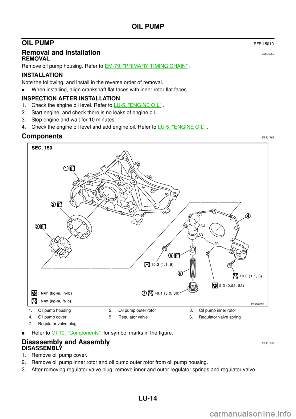
lRefer toGI-10, "Components"for symbol marks in the figure.
Disassembly and AssemblyEBS01E5E
DISASSEMBLY
1. Remove oil pump cover.
2. Remove oil pump inner rotor and oil pump outer rotor from oil pump housing.
3. After removing regulator valve plug, remove inner and outer regulator springs and regulator valve.
1. Oil pump housing 2. Oil pump outer rotor 3. Oil pump inner rotor
4. Oil pump cover 5. Regulator valve 6. Regulator valve spring
7. Regulator valve plug
PBIC4055E
Page 2509 of 3171
MTC-122
REFRIGERANT LINES
Removal and Installation for Compressor
EJS005HC
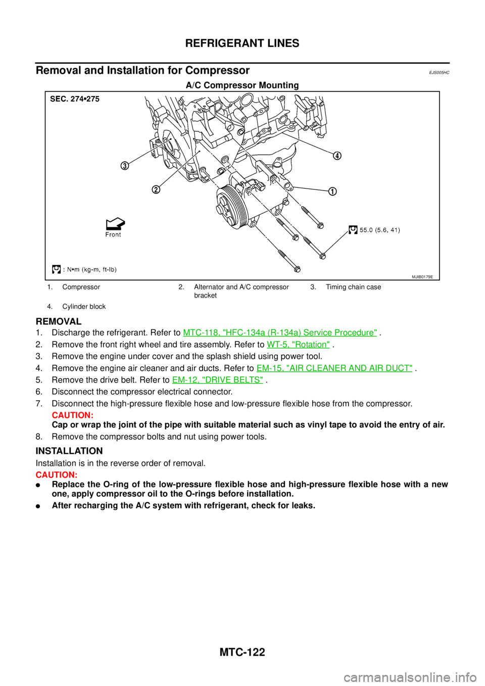
A/C Compressor Mounting
REMOVAL
1. Discharge the refrigerant. Refer toMTC-118, "HFC-134a (R-134a) Service Procedure".
2. Remove the front right wheel and tire assembly. Refer toWT-5, "
Rotation".
3. Remove the engine under cover and the splash shield using power tool.
4. Remove the engine air cleaner and air ducts. Refer toEM-15, "
AIR CLEANER AND AIR DUCT".
5. Remove the drive belt. Refer toEM-12, "
DRIVE BELTS".
6. Disconnect the compressor electrical connector.
7. Disconnect the high-pressure flexible hose and low-pressure flexible hose from the compressor.
CAUTION:
Cap or wrap the joint of the pipe with suitable material such as vinyl tape to avoid the entry of air.
8. Remove the compressor bolts and nut using power tools.
INSTALLATION
Installation is in the reverse order of removal.
CAUTION:
lReplace the O-ring of the low-pressure flexible hose and high-pressure flexible hose with a new
one, apply compressor oil to the O-rings before installation.
lAfter recharging the A/C system with refrigerant, check for leaks.
MJIB0179E
1. Compressor 2. Alternator and A/C compressor
bracket3. Timing chain case
4. Cylinder block