2005 NISSAN NAVARA Timing chain
[x] Cancel search: Timing chainPage 476 of 3171
ATC-142
REFRIGERANT LINES
Removal and Installation for Compressor
EJS006CN
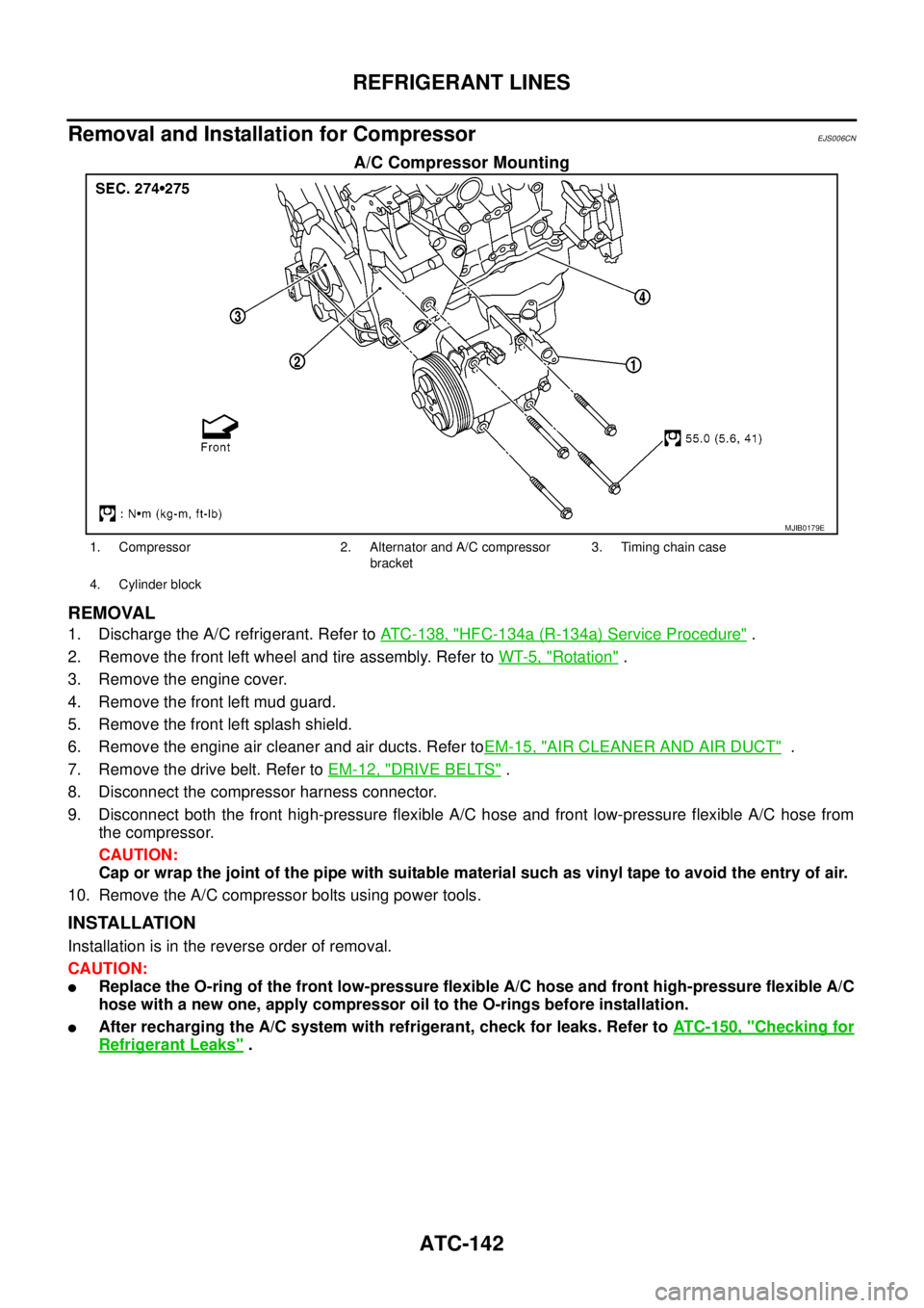
A/C Compressor Mounting
REMOVAL
1. Discharge the A/C refrigerant. Refer toATC-138, "HFC-134a (R-134a) Service Procedure".
2. Remove the front left wheel and tire assembly. Refer toWT-5, "
Rotation".
3. Remove the engine cover.
4. Remove the front left mud guard.
5. Remove the front left splash shield.
6. Remove the engine air cleaner and air ducts. Refer toEM-15, "
AIR CLEANER AND AIR DUCT".
7. Remove the drive belt. Refer toEM-12, "
DRIVE BELTS".
8. Disconnect the compressor harness connector.
9. Disconnect both the front high-pressure flexible A/C hose and front low-pressure flexible A/C hose from
the compressor.
CAUTION:
Cap or wrap the joint of the pipe with suitable material such as vinyl tape to avoid the entry of air.
10. Remove the A/C compressor bolts using power tools.
INSTALLATION
Installation is in the reverse order of removal.
CAUTION:
lReplace the O-ring of the front low-pressure flexible A/C hose and front high-pressure flexible A/C
hose with a new one, apply compressor oil to the O-rings before installation.
lAfter recharging the A/C system with refrigerant, check for leaks. Refer toATC-150, "Checking for
Refrigerant Leaks".
MJIB0179E
1. Compressor 2. Alternator and A/C compressor
bracket3. Timing chain case
4. Cylinder block
Page 1062 of 3171
EC-82
DTC P0016 CKP - CMP CORRELATION
DTC P0016 CKP - CMP CORRELATION
PFP:10328
On Board Diagnosis LogicEBS01KDF
The MI will not light up for this self-diagnosis.
NOTE:
If DTC P0016 is displayed with DTC P0652 or P0653, first perform the trouble diagnosis for DTC P0652
or P0653. Refer toEC-227, "
DTC P0652, P0653 SENSOR POWER SUPPLY".
DTC Confirmation ProcedureEBS01KDG
NOTE:
If DTC Confirmation Procedure has been previously conducted, always turn ignition switch OFF and wait at
least 10 seconds before conducting the next test.
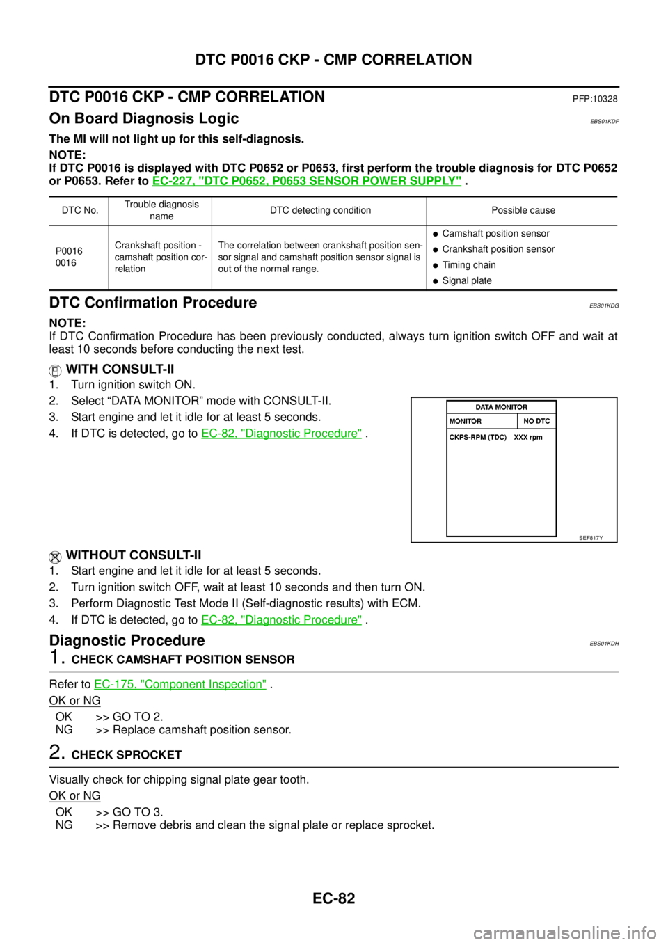
WITH CONSULT-II
1. Turn ignition switch ON.
2. Select “DATA MONITOR” mode with CONSULT-II.
3. Start engine and let it idle for at least 5 seconds.
4. If DTC is detected, go toEC-82, "
Diagnostic Procedure".
WITHOUT CONSULT-II
1. Start engine and let it idle for at least 5 seconds.
2. Turn ignition switch OFF, wait at least 10 seconds and then turn ON.
3. Perform Diagnostic Test Mode II (Self-diagnostic results) with ECM.
4. If DTC is detected, go toEC-82, "
Diagnostic Procedure".
Diagnostic ProcedureEBS01KDH
1.CHECK CAMSHAFT POSITION SENSOR
Refer toEC-175, "
Component Inspection".
OK or NG
OK >> GO TO 2.
NG >> Replace camshaft position sensor.
2.CHECK SPROCKET
Visually check for chipping signal plate gear tooth.
OK or NG
OK >> GO TO 3.
NG >> Remove debris and clean the signal plate or replace sprocket.
DTC No.Trouble diagnosis
nameDTC detecting condition Possible cause
P0016
0016Crankshaft position -
camshaft position cor-
relationThe correlation between crankshaft position sen-
sor signal and camshaft position sensor signal is
out of the normal range.
lCamshaft position sensor
lCrankshaft position sensor
lTiming chain
lSignal plate
SEF817Y
Page 1063 of 3171
DTC P0016 CKP - CMP CORRELATION
EC-83
C
D
E
F
G
H
I
J
K
L
MA
EC
3.CHECK CRANKSHAFT POSITION SENSOR
Refer toEC-164, "
Component Inspection".
OK or NG
OK >> GO TO 4.
NG >> Replace crankshaft position sensor.
4.CHECK GEAR TOOTH
Visually check for chipping signal plate gear tooth.
OK or NG
OK >> GO TO 5.
NG >> Replace the signal plate.
5.CHECK TIMING CHAIN
Refer toEM-73, "
SECONDARY TIMING CHAIN"andEM-79, "PRIMARY TIMING CHAIN".
OK or NG
OK >> GO TO 6.
NG >> Replace timing chain.
6.CHECK INTERMITTENT INCIDENT
Refer toEC-70, "
TROUBLE DIAGNOSIS FOR INTERMITTENT INCIDENT".
>>INSPECTION END
Page 1384 of 3171
EM-2
Components ........................................................... 42
Removal and Installation ........................................ 42
INSPECTION BEFORE REMOVAL ..................... 42
REMOVAL ........................................................... 42
INSTALLATION .................................................... 43
INJECTION TUBE AND FUEL INJECTOR .............. 44
Components ........................................................... 44
Removal and Installation ........................................ 44
REMOVAL ........................................................... 44
INSTALLATION .................................................... 46
INSPECTION AFTER INSTALLATION ................ 48
FUEL PUMP .............................................................. 49
Components ........................................................... 49
Removal and Installation ........................................ 49
REMOVAL ........................................................... 49
INSPECTION AFTER REMOVAL ........................ 52
INSTALLATION .................................................... 52
ROCKER COVER ..................................................... 56
Components ........................................................... 56
Removal and Installation ........................................ 56
REMOVAL ........................................................... 56
INSTALLATION .................................................... 57
INSPECTION AFTER INSTALLATION ................ 58
CAMSHAFT ............................................................... 59
Components ........................................................... 59
Removal and Installation ........................................ 59
REMOVAL ........................................................... 59
INSPECTION AFTER REMOVAL ........................ 60
INSTALLATION .................................................... 63
INSPECTION AFTER INSTALLATION ................ 65
Valve Clearance ...................................................... 66
INSPECTION ....................................................... 66
ADJUSTMENTS .................................................. 67
OIL SEAL .................................................................. 70
Removal and Installation of Valve Oil Seal ............. 70
REMOVAL ........................................................... 70
INSTALLATION .................................................... 70
Removal and Installation of Front Oil Seal ............. 71
REMOVAL ........................................................... 71
INSTALLATION .................................................... 71
Removal and Installation of Rear Oil Seal .............. 72
REMOVAL ........................................................... 72
INSTALLATION .................................................... 72
SECONDARY TIMING CHAIN .................................. 73
Components ........................................................... 73
Removal and Installation ........................................ 73
REMOVAL ........................................................... 73
INSPECTION AFTER REMOVAL ........................ 75
INSTALLATION .................................................... 75
INSPECTION AFTER INSTALLATION ................ 77
PRIMARY TIMING CHAIN ........................................ 79
Components ........................................................... 79
Removal and Installation ........................................ 80
REMOVAL ........................................................... 80
INSPECTION AFTER REMOVAL ........................ 84
INSTALLATION .................................................... 85
INSPECTION AFTER INSTALLATION ................ 91CYLINDER HEAD ..................................................... 92
On-Vehicle Service ................................................. 92
CHECKING COMPRESSION PRESSURE ......... 92
Components ............................................................ 93
Removal and Installation ......................................... 94
REMOVAL ............................................................ 94
INSPECTION AFTER REMOVAL ........................ 94
INSTALLATION .................................................... 96
INSPECTION AFTER INSTALLATION ................ 98
Components ............................................................ 99
Disassembly and Assembly .................................... 99
DISASSEMBLY .................................................... 99
ASSEMBLY ........................................................100
INSPECTION AFTER DISASSEMBLY ..............101
ENGINE ASSEMBLY ...............................................106
Components ..........................................................106
Removal and Installation .......................................106
REMOVAL ..........................................................107
INSTALLATION ..................................................108
INSPECTION AFTER INSTALLATION ..............108
CYLINDER BLOCK .................................................110
Components ..........................................................110
Disassembly and Assembly .................................. 111
DISASSEMBLY .................................................. 111
ASSEMBLY ........................................................114
How to Select Piston and Bearing ........................121
DESCRIPTION ..................................................121
HOW TO SELECT PISTON ...............................121
HOW TO SELECT CONNECTING ROD BEAR-
ING .....................................................................122
HOW TO SELECT MAIN BEARING ..................123
Inspection After Disassembly ................................124
CRANKSHAFT END PLAY ................................124
CONNECTING ROD SIDE CLEARANCE .........125
PISTON TO PISTON PIN CLEARANCE ...........125
PISTON RING SIDE CLEARANCE ...................126
PISTON RING END GAP ..................................126
CONNECTING ROD BEND AND TORSION .....127
CONNECTING ROD BIG END INNER DIAME-
TER ....................................................................127
CONNECTING ROD BUSHING OIL CLEAR-
ANCE .................................................................127
CYLINDER BLOCK TOP SURFACE DISTOR-
TION ..................................................................128
MAIN BEARING HOUSING INNER DIAMETER.128
PISTON TO CYLINDER BORE CLEARANCE ..129
CRANKSHAFT MAIN JOURNAL DIAMETER ...130
CRANKSHAFT PIN JOURNAL DIAMETER ......130
CRANKSHAFT OUT-OF-ROUND AND TAPER.130
CRANKSHAFT RUNOUT ..................................131
CONNECTING ROD BEARING OIL CLEAR-
ANCE .................................................................131
MAIN BEARING OIL CLEARANCE ...................132
CRUSH HEIGHT OF MAIN BEARING ..............132
CRUSH HEIGHT OF CONNECTING ROD
Page 1393 of 3171
NOISE, VIBRATION AND HARSHNESS (NVH) TROUBLESHOOTING
EM-11
C
D
E
F
G
H
I
J
K
L
MA
EM
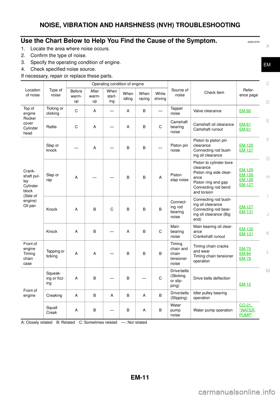
Use the Chart Below to Help You Find the Cause of the Symptom.EBS01E5R
1. Locate the area where noise occurs.
2. Confirm the type of noise.
3. Specify the operating condition of engine.
4. Check specified noise source.
If necessary, repair or replace these parts.
A: Closely related B: Related C: Sometimes related —: Not relatedLocation
of noiseType of
noiseOperating condition of engine
Source of
noiseCheck itemRefer-
ence page Before
warm-
upAfter
warm-
upWhen
start-
ingWhen
idlingWhen
racingWhile
driving
To p o f
engine
Rocker
cover
Cylinder
headTicking or
clickingCA—AB—Tappet
noiseValve clearanceEM-66
Rattle C A — A B CCamshaft
bearing
noiseCamshaft oil clearance
Camshaft runoutEM-61EM-61
Crank-
shaft pul-
ley
Cylinder
block
(Side of
engine)
Oil panSlap or
knock—A—BB—Piston pin
noisePiston to piston pin
clearance
Connecting rod bush-
ing oil clearanceEM-125
EM-127
Slap or
rapA ——BBAPiston
slap noisePiston to cylinder bore
clearance
Piston ring side clear-
ance
Piston ring end gap
Connecting rod bend
and torsionEM-129EM-126
EM-126
EM-127
Knock A B C B B BConnect-
ing rod
bearing
noiseConnecting rod bush-
ing oil clearance
Connecting rod bear-
ing oil clearance (Big
end)EM-127EM-131
Knock A B — A B CMain
bearing
noiseMain bearing oil clear-
ance
Crankshaft runoutEM-132EM-131
Front of
engine
Timing
chain
caseTapping or
tickingA A —BBBTiming
chain and
chain
tensioner
noiseTiming chain cracks
and wear
Timing chain tensioner
operationEM-75
EM-84
EM-79
Front of
engineSqueak-
ing or fizz-
ingAB—B—CDrive belts
(Sticking
or slip-
ping)Drive belts deflection
EM-12
CreakingA B ABABDrive belts
(Slipping)Idler pulley bearing
operation
Squall
CreakA B —BABWater
pump
noiseWater pump operationCO-21,
"WATER
PUMP"
Page 1424 of 3171
EM-42
VACUUM PUMP
VACUUM PUMP
PFP:41920
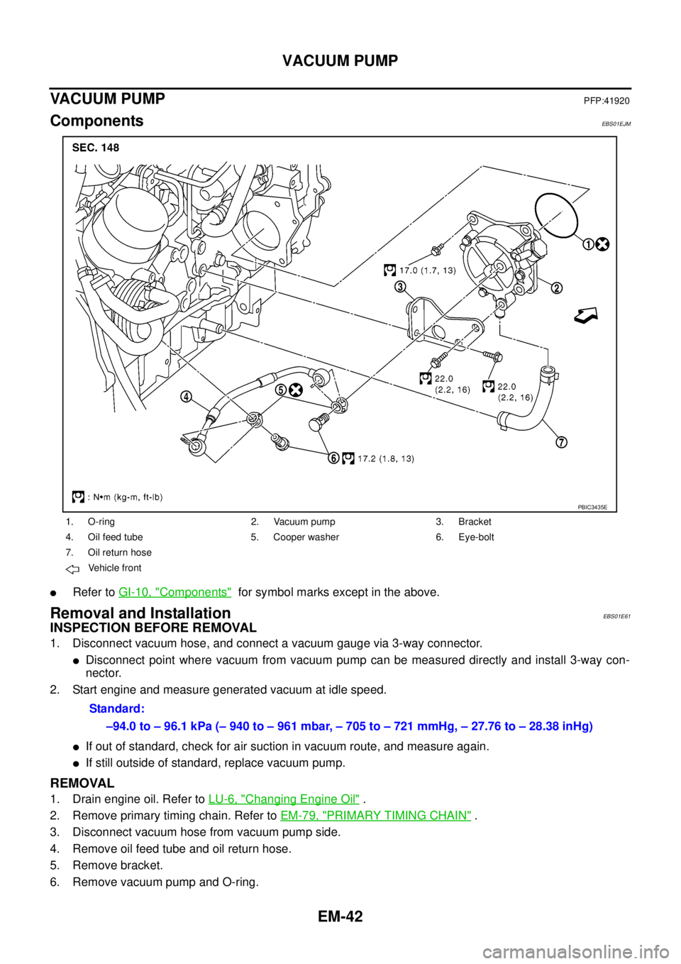
ComponentsEBS01EJM
lRefer toGI-10, "Components"for symbol marks except in the above.
Removal and InstallationEBS01E61
INSPECTION BEFORE REMOVAL
1. Disconnect vacuum hose, and connect a vacuum gauge via 3-way connector.
lDisconnect point where vacuum from vacuum pump can be measured directly and install 3-way con-
nector.
2. Start engine and measure generated vacuum at idle speed.
lIf out of standard, check for air suction in vacuum route, and measure again.
lIf still outside of standard, replace vacuum pump.
REMOVAL
1. Drain engine oil. Refer toLU-6, "Changing Engine Oil".
2. Remove primary timing chain. Refer toEM-79, "
PRIMARY TIMING CHAIN".
3. Disconnect vacuum hose from vacuum pump side.
4. Remove oil feed tube and oil return hose.
5. Remove bracket.
6. Remove vacuum pump and O-ring.
1. O-ring 2. Vacuum pump 3. Bracket
4. Oil feed tube 5. Cooper washer 6. Eye-bolt
7. Oil return hose
Vehicle front
PBIC3435E
Standard:
–94.0 to – 96.1 kPa (– 940 to – 961 mbar, – 705 to – 721 mmHg, – 27.76 to – 28.38 inHg)
Page 1431 of 3171
FUEL PUMP
EM-49
C
D
E
F
G
H
I
J
K
L
MA
EM
FUEL PUMPPFP:17042
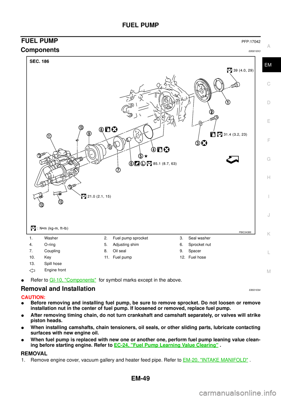
ComponentsEBS01EK3
lRefer toGI-10, "Components"for symbol marks except in the above.
Removal and InstallationEBS01E64
CAUTION:
lBefore removing and installing fuel pump, be sure to remove sprocket. Do not loosen or remove
installation nut in the center of fuel pump. If loosened or removed, replace fuel pump.
lAfter removing timing chain, do not turn crankshaft and camshaft separately, or valves will strike
piston heads.
lWhen installing camshafts, chain tensioners, oil seals, or other sliding parts, lubricate contacting
surfaces with new engine oil.
lWhen fuel pump is replaced with new one or another one, perform fuel pump leaning value clean-
ing before starting engine. Refer toEC-24, "
Fuel Pump Learning Value Clearing".
REMOVAL
1. Remove engine cover, vacuum gallery and heater feed pipe. Refer toEM-20, "INTAKE MANIFOLD".
1. Washer 2. Fuel pump sprocket 3. Seal washer
4. O-ring 5. Adjusting shim 6. Sprocket nut
7. Coupling 8. Oil seal 9. Spacer
10. Key 11. Fuel pump 12. Fuel hose
13. Spill hose
Engine front
PBIC3438E
Page 1432 of 3171
EM-50
FUEL PUMP
2. Remove fuel hose and spill hose from fuel pump. Refer toEM-44, "INJECTION TUBE AND FUEL INJEC-
TOR".
CAUTION:
Be careful not to spill fuel in the engine component.
3. Disconnect harness connectors from fuel pump.
4. Remove injection tube center, clip and insert rubber. Refer toEM-44, "
INJECTION TUBE AND FUEL
INJECTOR".
CAUTION:
Be careful not to spill fuel in the engine component.
5. Remove secondary timing chain. Refer toEM-73, "
SECONDARY TIMING CHAIN".
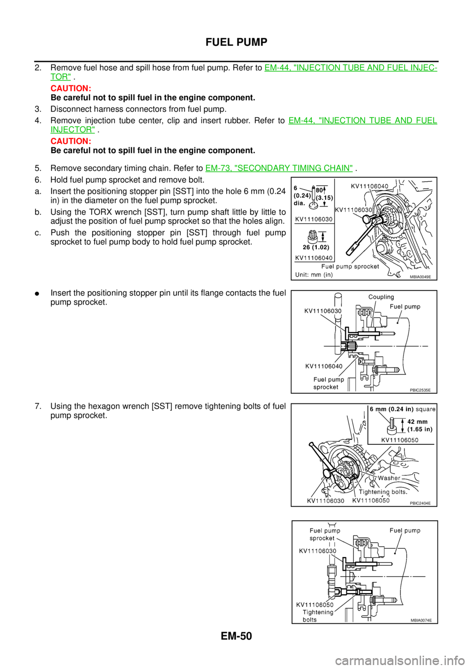
6. Hold fuel pump sprocket and remove bolt.
a. Insert the positioning stopper pin [SST] into the hole 6 mm (0.24
in) in the diameter on the fuel pump sprocket.
b. Using the TORX wrench [SST], turn pump shaft little by little to
adjust the position of fuel pump sprocket so that the holes align.
c. Push the positioning stopper pin [SST] through fuel pump
sprocket to fuel pump body to hold fuel pump sprocket.
lInsert the positioning stopper pin until its flange contacts the fuel
pump sprocket.
7. Using the hexagon wrench [SST] remove tightening bolts of fuel
pump sprocket.
MBIA0049E
PBIC2535E
PBIC2404E
MBIA0074E