Page 1434 of 3171
EM-52
FUEL PUMP
13. Loosen sprocket nut with the TORX wrench [SST].
14. Remove coupling with a suitable puller.
15. Remove spacer from fuel pump.
16. Remove oil seal from spacer.
INSPECTION AFTER REMOVAL
Timing Chain
Check for cracks and excessive wear at roller links. Replace
timing chain if necessary.
INSTALLATION
1. Install new oil seal to spacer.
2. Install spacer to fuel pump.
MBIA0013E
MBIA0014E
SEM984C
MBIA0045E
Page 1437 of 3171
FUEL PUMP
EM-55
C
D
E
F
G
H
I
J
K
L
MA
EM
13. Install secondary timing chain. Refer toEM-73, "SECONDARY TIMING CHAIN".
14. Following steps below, install injection tube center. Refer toEM-44, "
INJECTION TUBE AND FUEL
INJECTOR".
a. Pre-set clip and insert rubber to injection tube center.
b. Pre-tight nut of injection tube center to fuel pump and fuel rail by hand. (until seal surface touched)
c. Adjust clip dimension and tight bolt for clip to intake manifold by tool.
d. Tight nut of injection tube center to fuel pump by tool.
e. Tight nut of injection tube center to fuel rail by tool.
15. Connect the harness connector to fuel pump.
16. Install fuel hoses. Refer toEM-44, "
INJECTION TUBE AND FUEL INJECTOR".
17. Hereafter, install in the reverse order of removal.
CAUTION:
When fuel pump is replaced with new one or another one, perform fuel pump leaning value clean-
ing before starting engine. Refer toEC-24, "
Fuel Pump Learning Value Clearing".
Page 1442 of 3171

EM-60
CAMSHAFT
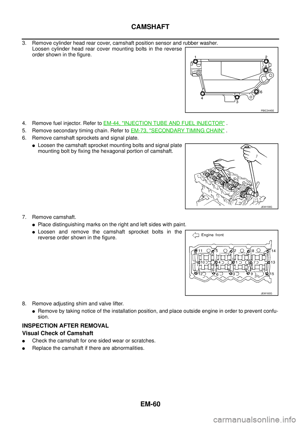
3. Remove cylinder head rear cover, camshaft position sensor and rubber washer.
Loosen cylinder head rear cover mounting bolts in the reverse
order shown in the figure.
4. Remove fuel injector. Refer toEM-44, "
INJECTION TUBE AND FUEL INJECTOR".
5. Remove secondary timing chain. Refer toEM-73, "
SECONDARY TIMING CHAIN".
6. Remove camshaft sprockets and signal plate.
lLoosen the camshaft sprocket mounting bolts and signal plate
mounting bolt by fixing the hexagonal portion of camshaft.
7. Remove camshaft.
lPlace distinguishing marks on the right and left sides with paint.
lLoosen and remove the camshaft sprocket bolts in the
reverse order shown in the figure.
8. Remove adjusting shim and valve lifter.
lRemove by taking notice of the installation position, and place outside engine in order to prevent confu-
sion.
INSPECTION AFTER REMOVAL
Visual Check of Camshaft
lCheck the camshaft for one sided wear or scratches.
lReplace the camshaft if there are abnormalities.
PBIC3445E
JEM159G
JEM160G
Page 1447 of 3171

CAMSHAFT
EM-65
C
D
E
F
G
H
I
J
K
L
MA
EM
7. Apply liquid gasket to cylinder head rear cover as shown in the
figure.
Use Genuine Liquid Gasket or Equivalent.
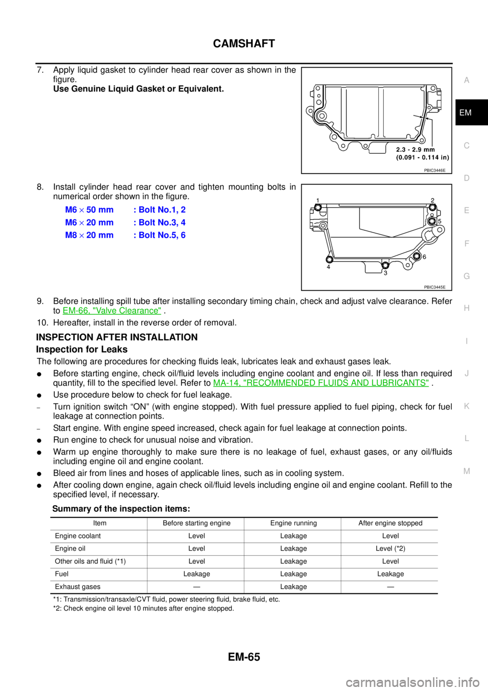
8. Install cylinder head rear cover and tighten mounting bolts in
numerical order shown in the figure.
9. Before installing spill tube after installing secondary timing chain, check and adjust valve clearance. Refer
toEM-66, "
Valve Clearance".
10. Hereafter, install in the reverse order of removal.
INSPECTION AFTER INSTALLATION
Inspection for Leaks
The following are procedures for checking fluids leak, lubricates leak and exhaust gases leak.
lBefore starting engine, check oil/fluid levels including engine coolant and engine oil. If less than required
quantity, fill to the specified level. Refer toMA-14, "
RECOMMENDED FLUIDS AND LUBRICANTS".
lUse procedure below to check for fuel leakage.
–Turn ignition switch “ON” (with engine stopped). With fuel pressure applied to fuel piping, check for fuel
leakage at connection points.
–Start engine. With engine speed increased, check again for fuel leakage at connection points.
lRun engine to check for unusual noise and vibration.
lWarm up engine thoroughly to make sure there is no leakage of fuel, exhaust gases, or any oil/fluids
including engine oil and engine coolant.
lBleed air from lines and hoses of applicable lines, such as in cooling system.
lAfter cooling down engine, again check oil/fluid levels including engine oil and engine coolant. Refill to the
specified level, if necessary.
Summary of the inspection items:
*1: Transmission/transaxle/CVT fluid, power steering fluid, brake fluid, etc.
*2: Check engine oil level 10 minutes after engine stopped.
PBIC3446E
M6´50 mm : Bolt No.1, 2
M6´20 mm : Bolt No.3, 4
M8´20 mm : Bolt No.5, 6
PBIC3445E
Item Before starting engine Engine running After engine stopped
Engine coolant Level Leakage Level
Engine oil Level Leakage Level (*2)
Other oils and fluid (*1) Level Leakage Level
Fuel Leakage Leakage Leakage
Exhaust gases — Leakage —
Page 1453 of 3171
OIL SEAL
EM-71
C
D
E
F
G
H
I
J
K
L
MA
EM
Removal and Installation of Front Oil SealEBS01EK8
REMOVAL
1. Remove the following parts.
lUndercover
lDrive belt; Refer toEM-12, "DRIVE BELTS".
lCrankshaft pulley; Refer toEM-79, "PRIMARY TIMING CHAIN".
2. Remove front oil seal with a suitable tool.
CAUTION:
Be careful not to damage oil pump housing and crankshaft.
INSTALLATION
1. Apply new engine oil to new front oil seal joint surface and seal lip.
2. Install front oil seal so that each seal lip is oriented as shown in
the figure.
lUsing the suitable drift [60 mm (2.36 in) dia.] (A), press fit the
oil seal (2) so that the dimension is as specified in the figure.
CAUTION:
Do not touch lips of oil seal. Make sure seal surfaces are
free of foreign materials.
3. Install in the reverse order of removal.
PBIC4050E
SEM715A
1 : Oil pump
PBIC4051E
Page 1455 of 3171

SECONDARY TIMING CHAIN
EM-73
C
D
E
F
G
H
I
J
K
L
MA
EM
SECONDARY TIMING CHAINPFP:13028
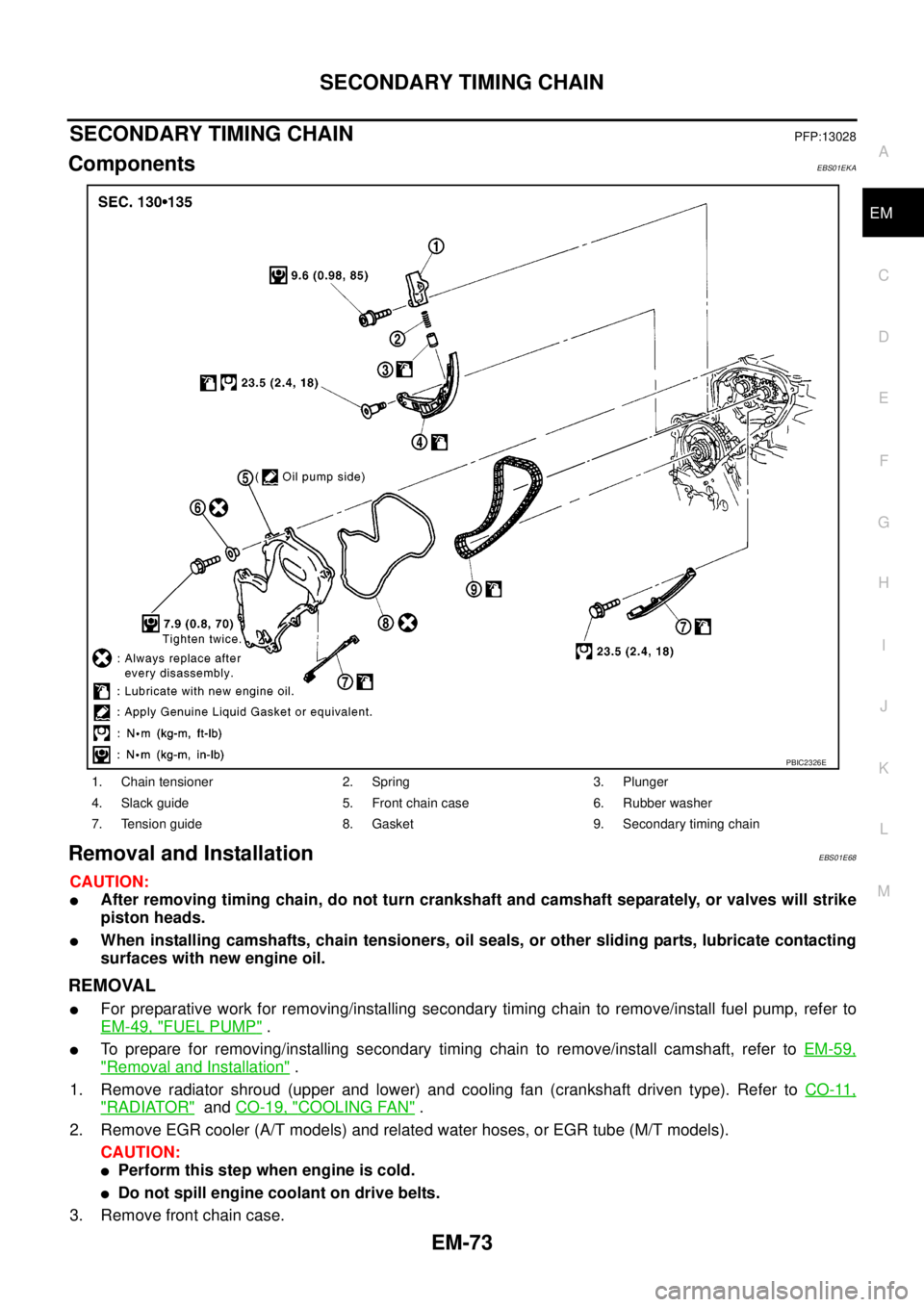
ComponentsEBS01EKA
Removal and InstallationEBS01E68
CAUTION:
lAfter removing timing chain, do not turn crankshaft and camshaft separately, or valves will strike
piston heads.
lWhen installing camshafts, chain tensioners, oil seals, or other sliding parts, lubricate contacting
surfaces with new engine oil.
REMOVAL
lFor preparative work for removing/installing secondary timing chain to remove/install fuel pump, refer to
EM-49, "
FUEL PUMP".
lTo prepare for removing/installing secondary timing chain to remove/install camshaft, refer toEM-59,
"Removal and Installation".
1. Remove radiator shroud (upper and lower) and cooling fan (crankshaft driven type). Refer toCO-11,
"RADIATOR"andCO-19, "COOLING FAN".
2. Remove EGR cooler (A/T models) and related water hoses, or EGR tube (M/T models).
CAUTION:
lPerform this step when engine is cold.
lDo not spill engine coolant on drive belts.
3. Remove front chain case.
1. Chain tensioner 2. Spring 3. Plunger
4. Slack guide 5. Front chain case 6. Rubber washer
7. Tension guide 8. Gasket 9. Secondary timing chain
PBIC2326E
Page 1456 of 3171
EM-74
SECONDARY TIMING CHAIN
lLoosen fixing bolts in reverse order of that shown in the figure
and remove them.
CAUTION:
lWhile front chain case is removed, cover openings to
prevent entry of foreign material into engine.
lDo not remove two mass dampers on the back of
cover.
4. Set the No. 1 piston to TDC on its compression stroke.
lTurn crankshaft pulley clockwise so that the alignment mark
(punched mark) on each camshaft sprocket is positioned as
showninthefigure.
lNo position indicator is provided on crankshaft pulley.
lWhen installing, color coded links on secondary timing
chain can be used as alignment marks. Marking may not
be necessary for removal; however, make alignment
marks as required because the alignment mark on fuel
pump sprocket may not be easy to see.
5. Remove chain tensioner.
a. Push the plunger of chain tensioner and keep it pressed with a
push pin.
JEM121G
SBIA0189E
SEM515G
JEM124G
Page 1457 of 3171
SECONDARY TIMING CHAIN
EM-75
C
D
E
F
G
H
I
J
K
L
MA
EM
b. Using the hexagon wrench [SST], remove bolts to remove chain
tensioner.
6. Remove slack guide.
lUsing the hexagon wrench [SST], remove bolt to remove
slack guide.
7. Remove tension guide.
8. Remove secondary timing chain.
lTiming chain alone can be removed without removing sprock-
ets.
INSPECTION AFTER REMOVAL
Timing Chain
Check for cracks and excessive wear at roller links. Replace
timing chain if necessary.
INSTALLATION
1. Install secondary timing chain.
SBIA0227E
SBIA0228E
JEM127G
SEM984C