Page 668 of 3171

BL-84
POWER DOOR LOCK — SUPER LOCK —
3.CHECK SUPER LOCK ACTUATOR
1. Reconnect BCM connector and front door lock actuator (driver side) connector.
2. Switch with a known-good front door lock actuator (driver side), and check if it operates normally.
OK or NG
OK >> Replace front door lock actuator (driver side).
NG >> Check the condition of the harness and the connector.
Check Super Lock Actuator (Passenger Side)EIS00DXN
1.CHECK SUPER LOCK SET SIGNAL CIRCUIT
1. Turn ignition switch OFF.
2. Disconnect BCM connector and front door lock actuator (pas-
senger side) connector.
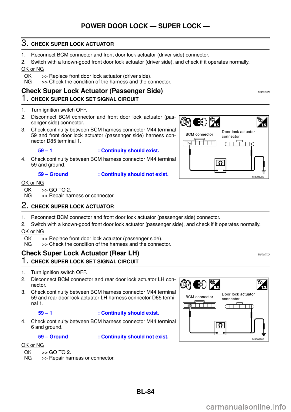
3. Check continuity between BCM harness connector M44 terminal
59 and front door lock actuator (passenger side) harness con-
nector D85 terminal 1.
4. Check continuity between BCM harness connector M44 terminal
59 and ground.
OK or NG
OK >> GO TO 2.
NG >> Repair harness or connector.
2.CHECK SUPER LOCK ACTUATOR
1. Reconnect BCM connector and front door lock actuator (passenger side) connector.
2. Switch with a known-good front door lock actuator (passenger side), and check if it operates normally.
OK or NG
OK >> Replace front door lock actuator (passenger side).
NG >> Check the condition of the harness and the connector.
Check Super Lock Actuator (Rear LH)EIS00DXO
1.CHECK SUPER LOCK SET SIGNAL CIRCUIT
1. Turn ignition switch OFF.
2. Disconnect BCM connector and rear door lock actuator LH con-
nector.
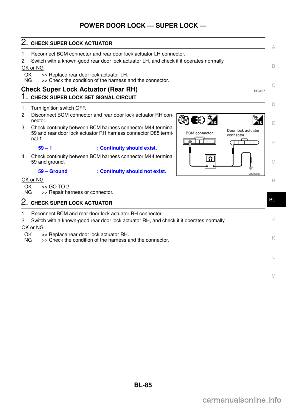
3. Check continuity between BCM harness connector M44 terminal
59 and rear door lock actuator LH harness connector D65 termi-
nal 1.
4. Check continuity between BCM harness connector M44 terminal
6 and ground.
OK or NG
OK >> GO TO 2.
NG >> Repair harness or connector.59 – 1 : Continuity should exist.
59 – Ground : Continuity should not exist.
MIIB0878E
59 – 1 : Continuity should exist.
59 – Ground : Continuity should not exist.
MIIB0878E
Page 669 of 3171

POWER DOOR LOCK — SUPER LOCK —
BL-85
C
D
E
F
G
H
J
K
L
MA
B
BL
2.CHECK SUPER LOCK ACTUATOR
1. Reconnect BCM connector and rear door lock actuator LH connector.
2. Switch with a known-good rear door lock actuator LH, and check if it operates normally.
OK or NG
OK >> Replace rear door lock actuator LH.
NG >> Check the condition of the harness and the connector.
Check Super Lock Actuator (Rear RH)EIS00DXP
1.CHECK SUPER LOCK SET SIGNAL CIRCUIT
1. Turn ignition switch OFF.
2. Disconnect BCM connector and rear door lock actuator RH con-
nector.
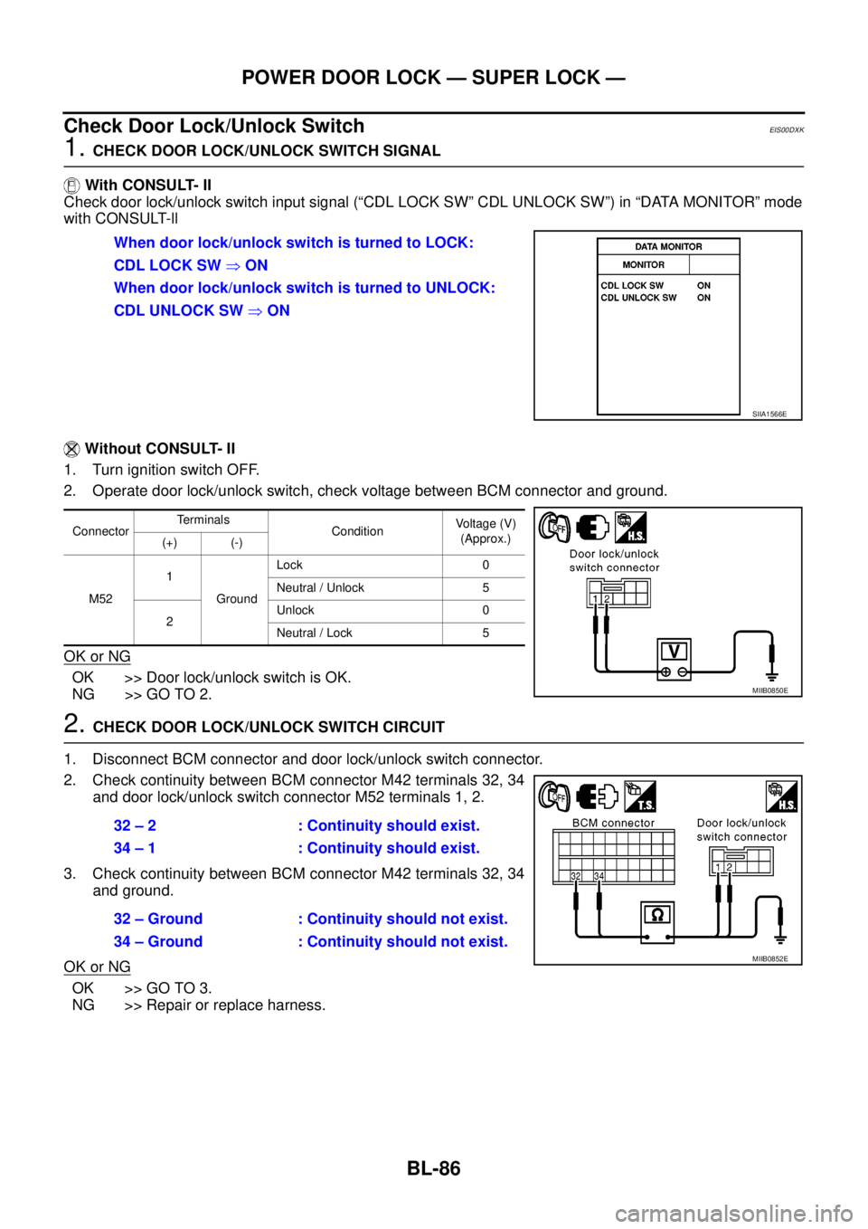
3. Check continuity between BCM harness connector M44 terminal
59 and rear door lock actuator RH harness connector D85 termi-
nal 1.
4. Check continuity between BCM harness connector M44 terminal
59 and ground.
OK or NG
OK >> GO TO 2.
NG >> Repair harness or connector.
2.CHECK SUPER LOCK ACTUATOR
1. Reconnect BCM and rear door lock actuator RH connector.
2. Switch with a known-good rear door lock actuator RH, and check if it operates normally.
OK or NG
OK >> Replace rear door lock actuator RH.
NG >> Check the condition of the harness and the connector.59 – 1 : Continuity should exist.
59 – Ground : Continuity should not exist.
MIIB0802E
Page 670 of 3171

BL-86
POWER DOOR LOCK — SUPER LOCK —
Check Door Lock/Unlock Switch
EIS00DXK
1.CHECK DOOR LOCK/UNLOCK SWITCH SIGNAL
With CONSULT- II
Check door lock/unlock switch input signal (“CDL LOCK SW” CDL UNLOCK SW”) in “DATA MONITOR” mode
with CONSULT-ll
Without CONSULT- II
1. Turn ignition switch OFF.
2. Operate door lock/unlock switch, check voltage between BCM connector and ground.
OK or NG
OK >> Door lock/unlock switch is OK.
NG >> GO TO 2.
2.CHECK DOOR LOCK/UNLOCK SWITCH CIRCUIT
1. Disconnect BCM connector and door lock/unlock switch connector.
2. Check continuity between BCM connector M42 terminals 32, 34
and door lock/unlock switch connector M52 terminals 1, 2.
3. Check continuity between BCM connector M42 terminals 32, 34
and ground.
OK or NG
OK >> GO TO 3.
NG >> Repair or replace harness.When door lock/unlock switch is turned to LOCK:
CDL LOCK SW�ON
When door lock/unlock switch is turned to UNLOCK:
CDL UNLOCK SW�ON
SIIA1566E
ConnectorTerminals
ConditionVoltage (V)
(Approx.)
(+) (-)
M521
GroundLock 0
Neutral / Unlock 5
2Unlock 0
Neutral / Lock 5
MIIB0850E
32 – 2 : Continuity should exist.
34 – 1 : Continuity should exist.
32 – Ground : Continuity should not exist.
34 – Ground : Continuity should not exist.
MIIB0852E
Page 671 of 3171
POWER DOOR LOCK — SUPER LOCK —
BL-87
C
D
E
F
G
H
J
K
L
MA
B
BL
3.CHECK GROUND CIRCUIT
Check continuity between door lock/unlock switch connector M52
terminal 3 and ground.
OK or NG
OK >> GO TO 4.
NG >> Replace harness.
4.CHECK DOOR LOCK/UNLOCK SWITCH
1. Turn ignition switch OFF.
2. Check continuity between door lock/unlock switch terminals 1, 2 and 3.
OK or NG
OK >> Check the condition of harness and connector.
NG >> Replace door lock/unlock switch.
Check Door Lock/Unlock Switch IndicatorEIS00DXL
1.CHECK DOOR LOCK/UNLOCK SWITCH INDICATOR SIGNAL
Operate door lock/unlock switch, check voltage between door lock/
unlock switch connector M52 terminal 5 and ground.
OK or NG
OK >> GO TO 2.
NG >> Replace BCM.3 – Ground : Continuity should exist.
MIIB0854E
Terminals Condition Continuity
1
3Lock YES
Neutral / Unlock NO
2Unlock YES
Neutral / Lock NO
MIIB0967E
5 – Ground : Approx. 5V
MIIB0855E
Page 672 of 3171

BL-88
POWER DOOR LOCK — SUPER LOCK —
2.CHECK DOOR LOCK/UNLOCK SWITCH INDICATOR CIRCUIT
1. Turn ignition switch OFF
2. Disconnect BCM connector and door lock/unlock switch connector.
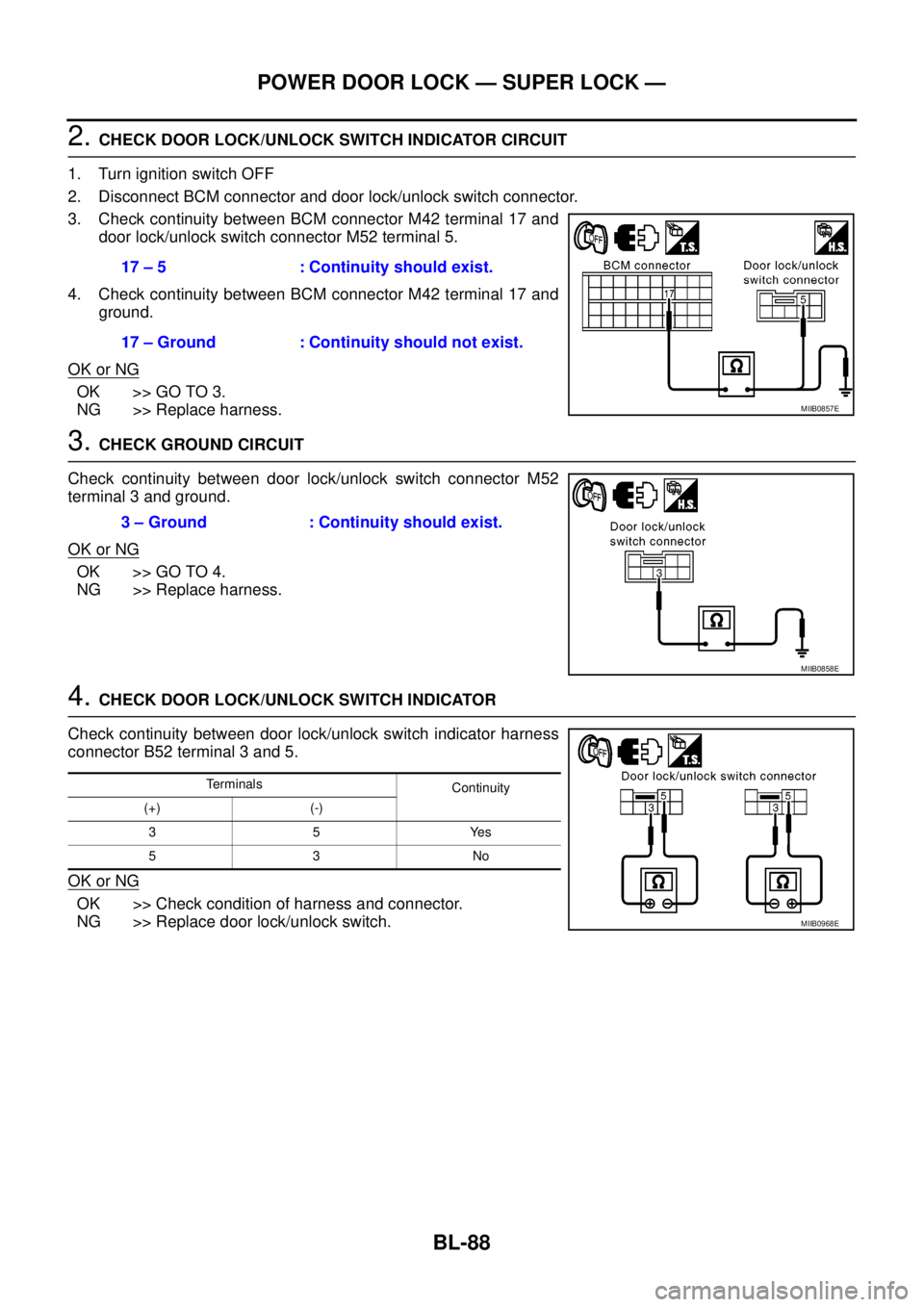
3. Check continuity between BCM connector M42 terminal 17 and
door lock/unlock switch connector M52 terminal 5.
4. Check continuity between BCM connector M42 terminal 17 and
ground.
OK or NG
OK >> GO TO 3.
NG >> Replace harness.
3.CHECK GROUND CIRCUIT
Check continuity between door lock/unlock switch connector M52
terminal 3 and ground.
OK or NG
OK >> GO TO 4.
NG >> Replace harness.
4.CHECK DOOR LOCK/UNLOCK SWITCH INDICATOR
Check continuity between door lock/unlock switch indicator harness
connector B52 terminal 3 and 5.
OK or NG
OK >> Check condition of harness and connector.
NG >> Replace door lock/unlock switch.17 – 5 : Continuity should exist.
17 – Ground : Continuity should not exist.
MIIB0857E
3 – Ground : Continuity should exist.
MIIB0858E
Terminals
Continuity
(+) (-)
35Yes
53No
MIIB0968E
Page 673 of 3171
MULTI-REMOTE CONTROL SYSTEM
BL-89
C
D
E
F
G
H
J
K
L
MA
B
BL
MULTI-REMOTE CONTROL SYSTEMPFP:25362
Component Parts and Harness Connector LocationEIS00DBD
KING CAB
1. Fuse block (J / B) fuse layout 2. Fuse and fusible link box 3. BCM M42, M43, M44
(View with instrument lower panel
LH removed)
4. Front door lock actuator
(Driver side) D745. Rear door switch NO.2 (LH) D72 6. Front door switch (Driver side) D94
7. Rear door switch NO.1 (LH) D71 8. Key switch M35
MIIB1030E
Page 674 of 3171
BL-90
MULTI-REMOTE CONTROL SYSTEM
DOUBLE CAB
1. Fuse block (J / B) fuse layout 2. Fuse and fusible link box 3. BCM M42, M43, M44
(View with instrument lower panel LH
removed)
4. Front door lock actuator
(Driver side) D105. Front door switch (Driver side) B19 6. Rear door lock actuator (LH) D65
7. Rear door switch (LH) B23 8. Key switch M35
MIIB1029E
Page 675 of 3171

MULTI-REMOTE CONTROL SYSTEM
BL-91
C
D
E
F
G
H
J
K
L
MA
B
BL
System DescriptionEIS00DBE
INPUTS
Power is supplied at all times
lto BCM terminal 57
lthrough 50A fusible link (letterG, located in the fuse and fusible link box).
lto BCM terminal 41
lthrough 10A fuse [No. 21, located in the fuse block (J/B)].
When the key switch is ON (key is inserted in ignition key cylinder), power is supplied
lto BCM terminal 5
lthrough key switch terminals 2 and 1
lthrough 10A fuse [No. 22, located in the fuse block (J/B)].
When the ignition switch is ACC or ON, power is supplied
lto BCM terminal 4
lthrough 10A fuse [No. 4, located in the fuse block (J/B)].
When the ignition switch is ON or START, power is supplied
lto BCM terminal 3
lthrough 10A fuse [No. 1, located in the fuse block (J/B)].
When the front door switch (driver side) is ON (door is OPEN), ground is supplied
lto BCM terminal 15
lthrough front door switch (driver side) terminal 2
lto front door switch (driver side) case ground.
When the front door switch (passenger side) is ON (door is OPEN), ground is supplied
lto BCM terminal 14
lthrough front door switch (passenger side) terminal 2
lto front door switch (passenger side) case ground.
When the rear door switch LH is ON (door is OPEN), ground is supplied
lto BCM terminal 16
lthrough rear door switch LH terminal 2
lto rear door switch LH case ground.
When the rear door switch RH is ON (door is OPEN), ground is supplied
lto BCM terminal 12
lthrough rear door switch RH terminal 2
lto rear door switch RH case ground.
The multi-remote control system controls operation of the
lpowerdoorlock
linterior lamp and ignition keyhole illumination
lhazard reminder
lauto door lock operation
OPERATING PROCEDURE
Power Door Lock Operation
BCM receives a LOCK signal from keyfob. BCM locks all doors with input of LOCK signal from keyfob.
When an UNLOCK signal is sent from keyfob once, driver's door is unlocked.
Then, if an UNLOCK signal is sent from keyfob again within 5 seconds, all doors are unlocked.
Hazard Reminder
When the doors are locked or unlocked by keyfob, power is supplied to hazard warning lamp.
Hazard reminder does not operate if any door switches are ON (any doors are OPEN).
How to change hazard and horn reminder mode
Hazard and horn reminder can be changed using “WORK SUPPORT” mode in “MULTI ANSWER BACK SET”.
Refer toBL-102, "
CONSULT-II Function (BCM)".