2005 NISSAN NAVARA headlamp
[x] Cancel search: headlampPage 604 of 3171
BL-20
FRONT FENDER
FRONT FENDER
PFP:63100
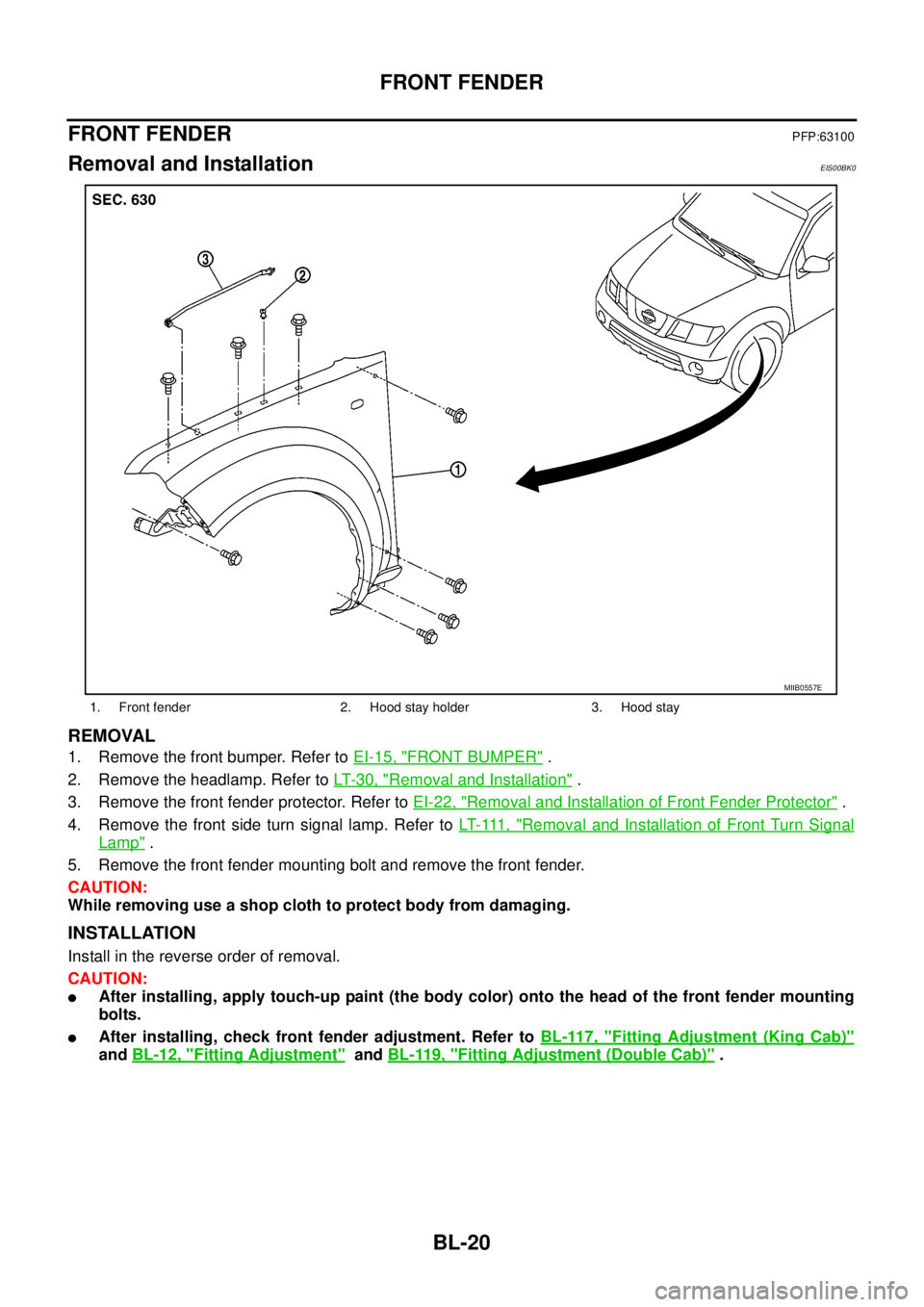
Removal and InstallationEIS00BK0
REMOVAL
1. Remove the front bumper. Refer toEI-15, "FRONT BUMPER".
2. Remove the headlamp. Refer toLT-30, "
Removal and Installation".
3. Remove the front fender protector. Refer toEI-22, "
Removal and Installation of Front Fender Protector".
4. Remove the front side turn signal lamp. Refer toLT- 111 , "
Removal and Installation of Front Turn Signal
Lamp".
5. Remove the front fender mounting bolt and remove the front fender.
CAUTION:
While removing use a shop cloth to protect body from damaging.
INSTALLATION
Install in the reverse order of removal.
CAUTION:
lAfter installing, apply touch-up paint (the body color) onto the head of the front fender mounting
bolts.
lAfter installing, check front fender adjustment. Refer toBL-117, "Fitting Adjustment (King Cab)"
andBL-12, "Fitting Adjustment"andBL-119, "Fitting Adjustment (Double Cab)".
1. Front fender 2. Hood stay holder 3. Hood stay
MIIB0557E
Page 857 of 3171
![NISSAN NAVARA 2005 Repair Workshop Manual TROUBLE DIAGNOSIS
BRC-35
[ABS]
C
D
E
G
H
I
J
K
L
MA
B
BRC
Symptom 4: ABS Function Does Not OperateEFS005UB
CAUTION:
ABS does not operate when speed is 10 km/h (6 MPH) or lower.
1.CHECK ABS WARNING LAM NISSAN NAVARA 2005 Repair Workshop Manual TROUBLE DIAGNOSIS
BRC-35
[ABS]
C
D
E
G
H
I
J
K
L
MA
B
BRC
Symptom 4: ABS Function Does Not OperateEFS005UB
CAUTION:
ABS does not operate when speed is 10 km/h (6 MPH) or lower.
1.CHECK ABS WARNING LAM](/manual-img/5/57362/w960_57362-856.png)
TROUBLE DIAGNOSIS
BRC-35
[ABS]
C
D
E
G
H
I
J
K
L
MA
B
BRC
Symptom 4: ABS Function Does Not OperateEFS005UB
CAUTION:
ABS does not operate when speed is 10 km/h (6 MPH) or lower.
1.CHECK ABS WARNING LAMP DISPLAY
Make sure that the ABS warning lamp is turned off after the ignition switch is turned ON or when driving.
OK or NG
OK >> GO TO procedure 3 “CHECK WHEEL SENSOR AND SENSOR ROTOR” of symptom1. Refer to
BRC-33, "
Symptom 1: Excessive ABS Function Operation Frequency".
NG >> Perform self-diagnosis. Refer toBRC-18, "
Self-Diagnosis".
Symptom 5: Pedal Vibration or ABS Operation Sound OccursEFS005UC
CAUTION:
Under the following conditions, ABS is activated and vibration is felt when brake pedal is lightly
depressed (just place a foot on it). However, this is normal.
lWhen shifting gears
lWhen driving on slippery road
lDuring cornering at high speed
lWhen passing over bumps or grooves [at approximately 50 mm (1.97 in) or more]
lWhen pulling away just after starting engine [at approximately 10 km/h (6 MPH) or more]
1.SYMPTOM CHECK 1
Check if there is pedal vibration or operation noise when the engine is started.
Do symptoms occur?
YES >> GO TO 2.
NO >> Perform self-diagnosis. Refer toBRC-18, "
Self-Diagnosis".
2.SYMPTOM CHECK 2
Check symptoms when electrical component (headlamps, etc.) switches are operated.
Do symptoms occur?
YES >> Check if there is a radio, antenna, antenna lead wire, or wiring close to the control unit. If there is,
move it farther away.
NO >> GO TO procedure 3²CHECK WHEEL SENSOR AND SENSOR ROTOR²of symptom 1. Refer to
BRC-33, "
Symptom 1: Excessive ABS Function Operation Frequency".
Symptom 6: ABS Warning Lamp Indication Is Not NormalEFS005UD
NOTE:
Lighting condition of ABS warning lamp refer toBRC-24, "
BASIC INSPECTION 3 ABS WARNING LAMP AND
BRAKE WARNING LAMP INSPECTION".
1.CHECK COMBINATION METER INDICATION
Check the combination meter indication and operation. Refer toDI-13, "
Self-Diagnosis Mode of Combination
Meter".
OK or NG
OK >> GO TO 2.
NG >> Combination meter is malfunctioning. Check combination meter. Refer toDI-4, "
COMBINATION
METERS".
Page 1018 of 3171
EC-38
TROUBLE DIAGNOSIS
Basic Inspection
EBS01KCV
Precaution:
Perform Basic Inspection without electrical or mechanical loads applied;
lHeadlamp switch is OFF.
lOn vehicles equipped with daytime light systems, set lighting switch to the 1st position to light
only small lamps.
lAir conditioner switch is OFF.
lHeater fan switch is OFF.
lRear defogger switch is OFF.
lHeat up switch is OFF.
lSteering wheel is in the straight-ahead position, etc.
1.INSPECTION START
1. Check service records for any recent repairs that may indicate a related incident.
2. Check the current need for scheduled maintenance, especially for fuel filter and air cleaner filter. Refer to
MA-8, "
PERIODIC MAINTENANCE".
3. Open engine hood and check the following:
–Harness connectors for improper connections
–Vacuum hoses for splits, kinks, or improper connections
–Wiring for improper connections, pinches, or cuts
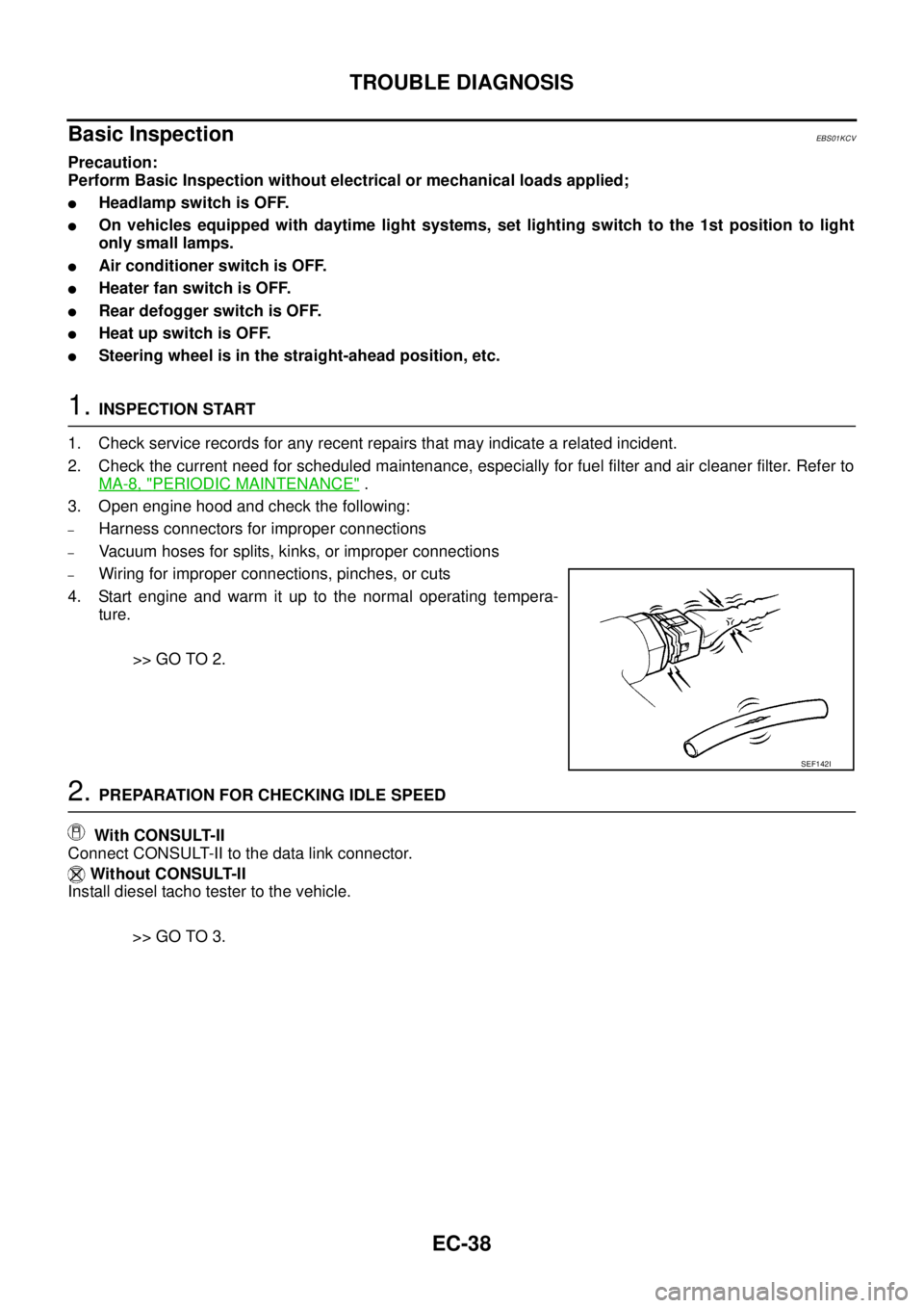
4. Start engine and warm it up to the normal operating tempera-
ture.
>> GO TO 2.
2.PREPARATION FOR CHECKING IDLE SPEED
With CONSULT-II
Connect CONSULT-II to the data link connector.
Without CONSULT-II
Install diesel tacho tester to the vehicle.
>> GO TO 3.
SEF142I
Page 1756 of 3171
IDX-4
ALPHABETICAL INDEX
Engine control system diagram and chart .........EC-15
Engine coolant ....................................................CO-7
Engine coolant temperature sensor (ECTS) ....EC-103
Engine oil .............................................................LU-5
Engine oil filter replacement .............................MA-26
Engine oil precautions ..........................................GI-7
Engine removal ...............................................EM-106
Engine room cover ............................................EM-20
Engine serial number ..........................................GI-58
Evaporator ....................................ATC-149,MTC-129
Exhaust manifold ..............................................EM-34
Exhaust system ...................................................EX-2
Exhaust system inspection ..................................EX-2
Expansion valve ............................ATC-150,MTC-130
F
F/FOG - Wiring diagram .....................................LT-74
F/PUMP - Wiring diagram ..EC-248,EC-254,EC-260,
EC-266
Final drive pre-inspection .................................FFD-18
Final drive removal and installation ..RFD-14,RFD-81
Flow charts .........................................................GI-24
Fluid temperature sensor (A/T) ........................AT-118
Fluids ................................................................MA-14
Fluorescent leak detector .............ATC-150,MTC-131
Flywheel (clutch) ................................................CL-17
Flywheel runout ..............................................EM-134
Fog lamp, front ....................................................LT-71
Foot lamp ..........................................................LT-145
Fork rod (M/T) ....................................................MT-23
Freeze frame data .............................................EC-28
Front brake solenoid valve .................AT-137,AT-139
Front bumper ......................................................EI-15
Front case (Transfer) ..........................TF-114,TF-120
Front combination lamp removal and installationLT-30
Front door ................BL-118,BL-120,BL-126,GW-35
Front Door Trim ..................................................EI-30
Front drive shaft (Transfer) ...TF-114,TF-120,TF-133
Front final drive removal and installation (4WD) ...........
FFD-15
Front fog lamp .....................................................LT-71
Front passenger air bag ..................................SRS-40
Front seat ...........................................................SE-20
Front seat belt ............................................SB-3,SB-5
Front seat belt pre-tensioner ...............SRS-3,SRS-47
Front side air bag ............................................SRS-43
Front washer ......................................................WW-4
Front wiper .........................................................WW-4
FRPS - Wiring diagram ....................................EC-120
FTS - Wiring diagram .......................................EC-115
Fuel cut control (at no load high engine speed) .EC-20
Fuel filler lid ......................................................BL-136
Fuel filter ............................................................EC-23
Fuel filter replacement ..........................................FL-4
Fuel gauge ............................................................DI-4
Fuel injection control system .............................EC-18
Fuel injector ............EC-25,EC-123,EC-125,EC-237
Fuel injector and fuel tube ................................EM-44
Fuel leak ............................................................EC-88
Fuel line inspection ..............................................FL-3
Fuel pumpEC-86,EC-217,EC-245,EC-251,EC-258,
EC-263
Fuel pump(Learning Value Clearing) .................EC-24
Fuel rail pressure sensor .................................EC-118
Fuel system .........................................................FL-3
Fuel tank ..............................................................FL-9
Fuel temperature sensor ..................................EC-113
Fuse ......................................................PG-74,PG-84
Fuse and fusible link box ..................................PG-84
Fusible link ............................................PG-74,PG-84
G
Garage jack and safety stand .............................GI-52
Gauges .................................................................DI-4
Gear components (M/T) ....................................MT-21
Generator ...........................................................SC-14
Generator - See Alternator ................................SC-14
Glass ........................GW-11,GW-35,GW-38,GW-43
Glove box lamp ................................................LT-162
GLOW - Wiring diagram ..................................EC-296
Glow plug ............................................EM-41,EC-295
Glow relay ........................................................EC-295
Grease ..............................................................MA-14
Ground distribution ...........................................PG-27
H
H/AIM - Wiring diagram .....................................LT-66
Harness connector ............................................PG-75
Harness layout ..................................................PG-38
Hazard warning lamp .........................................LT-97
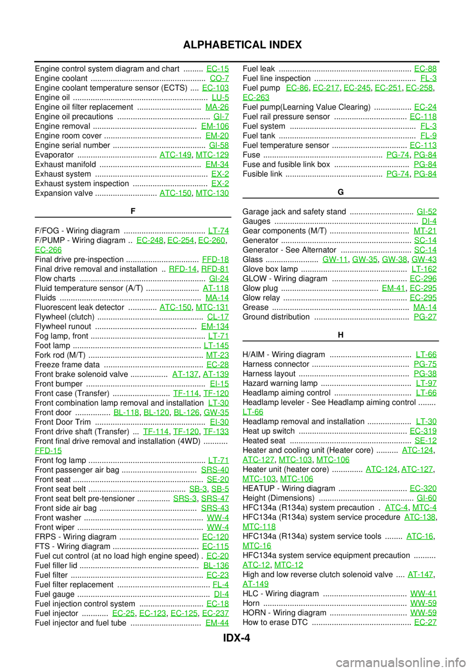
Headlamp aiming control ...................................LT-66
Headlamp leveler - See Headlamp aiming control ........
LT-66
Headlamp removal and installation ....................LT-30
Heat up switch .................................................EC-319
Heated seat .......................................................SE-12
Heater and cooling unit (Heater core) ..........ATC-124,
ATC-127
,MTC-103,MTC-106
Heater unit (heater core) ..............ATC-124,ATC-127,
MTC-103
,MTC-106
HEATUP - Wiring diagram ...............................EC-320
Height (Dimensions) ...........................................GI-60
HFC134a (R134a) system precaution .ATC-4,MTC-4
HFC134a (R134a) system service procedureATC-138,
MTC-118
HFC134a (R134a) system service tools ........ATC-16,
MTC-16
HFC134a system service equipment precaution ..........
ATC-12
,MTC-12
High and low reverse clutch solenoid valve ....AT-147,
AT-149
HLC - Wiring diagram ......................................WW-41
Horn .................................................................WW-59
HORN - Wiring diagram ...................................WW-59
How to erase DTC .............................................EC-27
Page 2084 of 3171
LT-1
LIGHTING SYSTEM
K ELECTRICAL
CONTENTS
C
D
E
F
G
H
I
J
L
M
SECTIONLT
A
B
LT
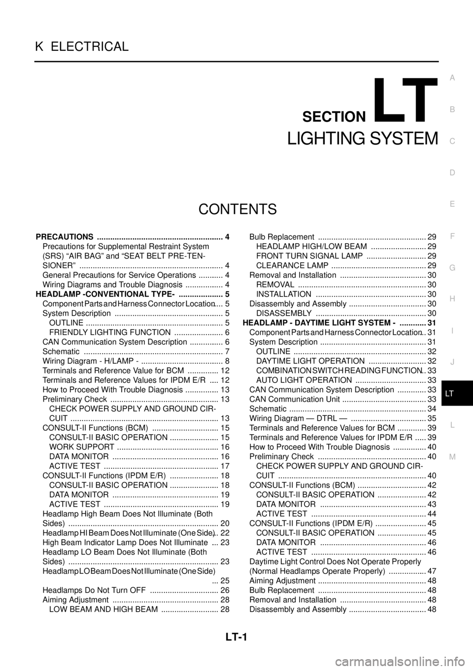
LIGHTING SYSTEM
PRECAUTIONS .......................................................... 4
Precautions for Supplemental Restraint System
(SRS)“AIRBAG”and“SEATBELTPRE-TEN-
SIONER” .................................................................. 4
General Precautions for Service Operations ............ 4
Wiring Diagrams and Trouble Diagnosis .................. 4
HEADLAMP -CONVENTIONAL TYPE- ..................... 5
Component Parts and Harness Connector Location..... 5
System Description .................................................. 5
OUTLINE ............................................................... 5
FRIENDLY LIGHTING FUNCTION ....................... 6
CAN Communication System Description ................ 6
Schematic ................................................................ 7
Wiring Diagram - H/LAMP - ...................................... 8
Terminals and Reference Value for BCM ............... 12
Terminals and Reference Values for IPDM E/R ..... 12
How to Proceed With Trouble Diagnosis ................ 13
Preliminary Check .................................................. 13
CHECK POWER SUPPLY AND GROUND CIR-
CUIT .................................................................... 13
CONSULT-II Functions (BCM) ............................... 15
CONSULT-II BASIC OPERATION ....................... 15
WORK SUPPORT ............................................... 16
DATA MONITOR ................................................. 16
ACTIVE TEST ..................................................... 17
CONSULT-II Functions (IPDM E/R) ....................... 18
CONSULT-II BASIC OPERATION ....................... 18
DATA MONITOR ................................................. 19
ACTIVE TEST ..................................................... 19
Headlamp High Beam Does Not Illuminate (Both
Sides) ..................................................................... 20
Headlamp HI Beam Does Not Illuminate (One Side)... 22
High Beam Indicator Lamp Does Not Illuminate .... 23
Headlamp LO Beam Does Not Illuminate (Both
Sides) ..................................................................... 23
Headlamp LO Beam Does Not Illuminate (One Side)
... 25
Headlamps Do Not Turn OFF ................................ 26
Aiming Adjustment ................................................. 28
LOW BEAM AND HIGH BEAM ........................... 28Bulb Replacement .................................................. 29
HEADLAMP HIGH/LOW BEAM .......................... 29
FRONT TURN SIGNAL LAMP ............................ 29
CLEARANCE LAMP ............................................ 29
Removal and Installation ........................................ 30
REMOVAL ........................................................... 30
INSTALLATION ................................................... 30
Disassembly and Assembly .................................... 30
DISASSEMBLY ................................................... 30
HEADLAMP - DAYTIME LIGHT SYSTEM - ............. 31
Component Parts and Harness Connector Location... 31
System Description ................................................. 31
OUTLINE ............................................................. 32
DAYTIME LIGHT OPERATION ........................... 32
COMBINATION SWITCH READING FUNCTION... 33
AUTO LIGHT OPERATION ................................. 33
CAN Communication System Description .............. 33
CAN Communication Unit ....................................... 33
Schematic ............................................................... 34
Wiring Diagram — DTRL — ................................... 35
Terminals and Reference Values for BCM .............. 39
Terminals and Reference Values for IPDM E/R ...... 39
How to Proceed With Trouble Diagnosis ................ 40
Preliminary Check .................................................. 40
CHECK POWER SUPPLY AND GROUND CIR-
CUIT .................................................................... 40
CONSULT-II Functions (BCM) ................................ 42
CONSULT-II BASIC OPERATION ....................... 42
DATA MONITOR ................................................. 43
ACTIVE TEST ..................................................... 44
CONSULT-II Functions (IPDM E/R) ........................ 45
CONSULT-II BASIC OPERATION ....................... 45
DATA MONITOR ................................................. 46
ACTIVE TEST ..................................................... 46
Daytime Light Control Does Not Operate Properly
(Normal Headlamps Operate Properly) .................. 47
Aiming Adjustment .................................................. 48
Bulb Replacement .................................................. 48
Removal and Installation ........................................ 48
Disassembly and Assembly .................................... 48
Page 2085 of 3171

LT-2
AUTO LIGHT SYSTEM ............................................. 49
Component Parts and Harness Connector Location... 49
System Description ................................................. 49
OUTLINE ............................................................. 49
COMBINATION SWITCH READING FUNCTION... 50
CAN Communication System Description .............. 50
Major Components and Functions .......................... 50
Schematic ............................................................... 51
Wiring Diagram — AUTO/L — ................................ 52
Terminals and Reference Values for BCM .............. 56
Terminals and Reference Values for IPDM E/R ...... 57
How to Proceed With Trouble Diagnosis ................ 57
Preliminary Check .................................................. 58
SETTING CHANGE FUNCTIONS ....................... 58
CHECK POWER SUPPLY AND GROUND CIR-
CUIT .................................................................... 58
CONSULT-II Function (BCM) .................................. 59
CONSULT-II OPERATION ................................... 59
WORK SUPPORT ............................................... 60
DATA MONITOR .................................................. 60
ACTIVE TEST ..................................................... 61
Trouble Diagnosis Chart by Symptom .................... 62
Lighting Switch Inspection ...................................... 62
Light and Rain Sensor System Inspection .............. 63
Removal and Installation of Light and Rain Sensor... 65
REMOVAL ........................................................... 65
INSTALLATION .................................................... 65
HEADLAMP AIMING CONTROL (MANUAL) ........... 66
Schematic ............................................................... 66
Wiring Diagram — H/AIM — ................................... 67
Removal and Installation ........................................ 70
Switch Circuit Inspection ........................................ 70
FRONT FOG LAMP .................................................. 71
Component Parts and Harness Connector Location... 71
System Description ................................................. 71
OUTLINE ............................................................. 71
COMBINATION SWITCH READING FUNCTION... 72
CAN Communication System Description .............. 72
Schematic ............................................................... 73
Wiring Diagram — F/FOG — .................................. 74
Terminals and Reference Values for BCM .............. 77
Terminals and Reference Values for IPDM E/R ...... 77
How to Proceed With Trouble Diagnosis ................ 78
Preliminary Check .................................................. 78
CHECK POWER SUPPLY AND GROUND CIR-
CUIT .................................................................... 78
CONSULT-II Functions (BCM) ................................ 79
CONSULT-II Functions (IPDM E/R) ........................ 79
Front Fog Lamps Do Not Illuminate (Both Sides) ... 80
Front Fog Lamp Does Not Illuminate (One Side) ... 82
Front Fog Lamp Indicator Lamp Does Not Illuminate... 83
Front Fog Lamps Do Not Turn OFF ........................ 84
Aiming Adjustment .................................................. 85
Bulb Replacement .................................................. 86
Removal and Installation of Front Fog Lamp .......... 86
REMOVAL ........................................................... 86
INSTALLATION .................................................... 86
REAR FOG LAMP ..................................................... 87
Component Parts and Harness Connector Location... 87System Description ................................................. 87
OUTLINE ............................................................. 87
COMBINATION SWITCH READING FUNCTION... 88
CAN Communication System Description .............. 88
CAN Communication Unit ....................................... 88
Wiring Diagram — R/FOG — .................................. 89
Terminals and Reference Values for BCM .............. 91
How to Proceed With Trouble Diagnosis ................ 91
Preliminary Check ................................................... 92
CHECK POWER SUPPLY AND GROUND CIR-
CUIT ..................................................................... 92
CONSULT-II Functions (BCM) ................................ 93
Rear Fog Lamp Does Not Operate ......................... 93
Rear Fog Lamp Indicator Lamp Does Not Illuminate... 95
Rear Fog Lamp Does Not Turn OFF ....................... 96
Bulb Replacement ................................................... 96
Removal and Installation ......................................... 96
TURN SIGNAL AND HAZARD WARNING LAMPS... 97
Component Parts and Harness Connector Location... 97
System Description ................................................. 97
OUTLINE ............................................................. 97
TURN SIGNAL OPERATION ............................... 97
HAZARD LAMP OPERATION ............................. 98
REMOTE KEYLESS ENTRY SYSTEM OPERA-
TION .................................................................... 99
COMBINATION SWITCH READING FUNCTION... 99
CAN Communication System Description .............. 99
Wiring Diagram — TURN — .................................100
Terminals and Reference Values for BCM ............102
How to Proceed With Trouble Diagnosis ..............103
Preliminary Check .................................................103
CHECK POWER SUPPLY AND GROUND CIR-
CUIT ...................................................................103
CONSULT-II Function (BCM) ................................105
CONSULT-II OPERATION .................................105
DATA MONITOR ................................................106
ACTIVE TEST ....................................................106
Turn Signal Lamp Does Not Operate ....................107
Hazard Warning Lamp Does Not Operate But Turn
Signal Lamps Operate ..........................................109
Turn Signal Indicator Lamp Does Not Operate .....110
Bulb Replacement (Front Turn Signal Lamp) ........ 111
Bulb Replacement (Rear Turn Signal Lamp) ........ 111
Bulb Replacement (Side Turn Signal Lamp) ......... 111
Removal and Installation of Front Turn Signal Lamp. 111
Removal and Installation of Rear Turn Signal Lamp. 111
Removal and Installation of Side Turn Signal Lamp. 111
REMOVAL .......................................................... 111
INSTALLATION .................................................. 111
LIGHTING AND TURN SIGNAL SWITCH ..............112
Removal and Installation .......................................112
REMOVAL ..........................................................112
INSTALLATION ..................................................112
HAZARD SWITCH ...................................................113
Removal and Installation .......................................113
REMOVAL ..........................................................113
INSTALLATION ..................................................113
COMBINATION SWITCH ........................................114
Wiring Diagram — COMBSW — ..........................114
Page 2086 of 3171
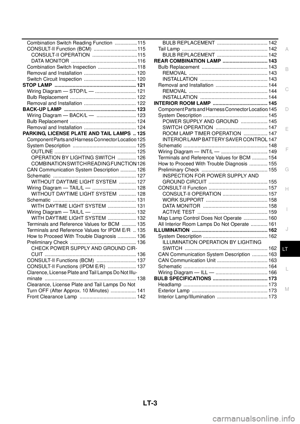
LT-3
C
D
E
F
G
H
I
J
L
MA
B
LT Combination Switch Reading Function ................. 115
CONSULT-II Function (BCM) ................................ 115
CONSULT-II OPERATION ................................. 115
DATA MONITOR ................................................ 116
Combination Switch Inspection ............................. 118
Removal and Installation ...................................... 120
Switch Circuit Inspection ...................................... 120
STOP LAMP ........................................................... 121
Wiring Diagram — STOP/L — .............................. 121
Bulb Replacement ................................................ 122
Removal and Installation ...................................... 122
BACK-UP LAMP .................................................... 123
Wiring Diagram — BACK/L — ............................. 123
Bulb Replacement ................................................ 124
Removal and Installation ...................................... 124
PARKING, LICENSE PLATE AND TAIL LAMPS ... 125
Component Parts and Harness Connector Location. 125
System Description .............................................. 125
OUTLINE ........................................................... 125
OPERATION BY LIGHTING SWITCH .............. 126
COMBINATION SWITCH READING FUNCTION. 126
CAN Communication System Description ............ 126
Schematic ............................................................ 127
WITHOUT DAYTIME LIGHT SYSTEM ............. 127
Wiring Diagram — TAIL/L — ................................ 128
WITHOUT DAYTIME LIGHT SYSTEM ............. 128
Schematic ............................................................ 131
WITH DAYTIME LIGHT SYSTEM ..................... 131
Wiring Diagram — TAIL/L — ................................ 132
WITH DAYTIME LIGHT SYSTEM ..................... 132
Terminals and Reference Values for BCM ........... 135
Terminals and Reference Values for IPDM E/R ... 135
How to Proceed With Trouble Diagnosis .............. 136
Preliminary Check ................................................ 136
CHECK POWER SUPPLY AND GROUND CIR-
CUIT .................................................................. 136
CONSULT-II Functions (BCM) ............................. 137
CONSULT-II Functions (IPDM E/R) ..................... 137
Clarence, License Plate and Tail Lamps Do Not Illu-
minate .................................................................. 138
Clearance, License Plate and Tail Lamps Do Not
Turn OFF (After Approx. 10 Minutes) ................... 141
Front Clearance Lamp ......................................... 142BULB REPLACEMENT .....................................142
Tail Lamp ..............................................................142
BULB REPLACEMENT .....................................142
REAR COMBINATION LAMP .................................143
Bulb Replacement ................................................143
REMOVAL .........................................................143
INSTALLATION .................................................143
Removal and Installation ......................................144
REMOVAL .........................................................144
INSTALLATION .................................................144
INTERIOR ROOM LAMP ........................................145
Component Parts and Harness Connector Location.145
System Description ...............................................145
POWER SUPPLY AND GROUND ....................145
SWITCH OPERATION ......................................147
ROOM LAMP TIMER OPERATION ..................147
INTERIOR LAMP BATTERY SAVER CONTROL.147
Schematic .............................................................148
Wiring Diagram — INT/L — ..................................149
Terminals and Reference Values for BCM ............154
How to Proceed With Trouble Diagnosis ..............155
Preliminary Check ................................................155
INSPECTION FOR POWER SUPPLY AND
GROUND CIRCUIT ...........................................155
CONSULT-II Function ...........................................157
CONSULT-II OPERATION .................................157
WORK SUPPORT .............................................158
DATA MONITOR ...............................................158
ACTIVE TEST ...................................................159
Map Lamp Control Does Not Operate ..................160
All Interior Room Lamps Do Not Operate .............161
ILLUMINATION .......................................................162
System Description ...............................................162
ILLUMINATION OPERATION BY LIGHTING
SWITCH ............................................................162
CAN Communication System Description ............163
CAN Communication Unit .....................................163
Schematic .............................................................164
Wiring Diagram — ILL — ......................................166
BULB SPECIFICATIONS ........................................173
Headlamp .............................................................173
Exterior Lamp .......................................................173
Interior Lamp/Illumination .....................................173
Page 2087 of 3171
LT-4
PRECAUTIONS
PRECAUTIONS
PFP:00011
Precautions for Supplemental Restraint System (SRS) “AIR BAG” and “SEAT
BELT PRE-TENSIONER”
EKS00N1L
The Supplemental Restraint System such as “AIR BAG” and “SEAT BELT PRE-TENSIONER”, used along
with a front seat belt, helps to reduce the risk or severity of injury to the driver and front passenger for certain
types of collision. Information necessary to service the system safely is included in the SRS and SB section of
this Service Manual.
WARNING:
lTo avoid rendering the SRS inoperative, which could increase the risk of personal injury or death
in the event of a collision which would result in air bag inflation, all maintenance must be per-
formed by an authorized NISSAN/INFINITI dealer.
lImproper maintenance, including incorrect removal and installation of the SRS, can lead to per-
sonal injury caused by unintentional activation of the system. For removal of Spiral Cable and Air
Bag Module, see the SRS section.
lDo not use electrical test equipment on any circuit related to the SRS unless instructed to in this
Service Manual. SRS wiring harnesses can be identified by yellow and/or orange harnesses or
harness connectors.
General Precautions for Service OperationsEKS00L4H
lNever work with wet hands.
lTurn the lighting switch OFF before disconnecting and connecting the connector.
lWhen checking the headlamp on/off operation, check it on vehicle and with the power connected to the
vehicle-side connector.
lDo not touch the headlamp bulb glass surface with bare hands or allow oil or grease to get on it. Do not
touch the headlamp bulb just after the headlamp is turned off, because it is very hot.
lWhen the bulb has burned out, wrap it in a thick vinyl bag and discard. Do not break the bulb.
lLeaving the bulb removed from the headlamp housing for a long period of time can deteriorate the perfor-
mance of the lens and reflector (dirt, clouding). Always prepare a new bulb and have it on hand when
replacing the bulb.
lDo not use organic solvent (paint thinner or gasoline) to clean lamps and to remove old sealant.
Wiring Diagrams and Trouble DiagnosisEKS00L4I
When you read wiring diagrams, refer to the following:
lRefer toGI-15, "How to Read Wiring Diagrams".
lRefer toPG-4, "POWER SUPPLY ROUTING CIRCUIT".
When you perform trouble diagnosis, refer to the following:
lRefer toGI-11, "HOW TO FOLLOW TEST GROUPS IN TROUBLE DIAGNOSES".
lRefer toGI-24, "How to Perform Efficient Diagnosis for an Electrical Incident".