Page 820 of 3171
BR-34
REAR DRUM BRAKE
Removal and Installation of Wheel Cylinder
EFS006AH
REMOVAL
1. Drain brake fluid. Refer toBR-10, "Drain and Refill".
2. Remove rear brake shoe assembly.
3. Remove brake tube from the wheel cylinder.
4. Remove bolts on the wheel cylinder, and then remove wheel cylinder from the back plate.
INSTALLATION
lInstallation is the reverse order of removal. Tighten bolts to the specified torque. Refer toBR-30, "Compo-
nents".
lRefill with new brake fluid and bleed air. Refer toBR-11, "Bleeding Brake System".
Disassembly and Assembly of Wheel CylinderEFS006AI
DISASSEMBLY
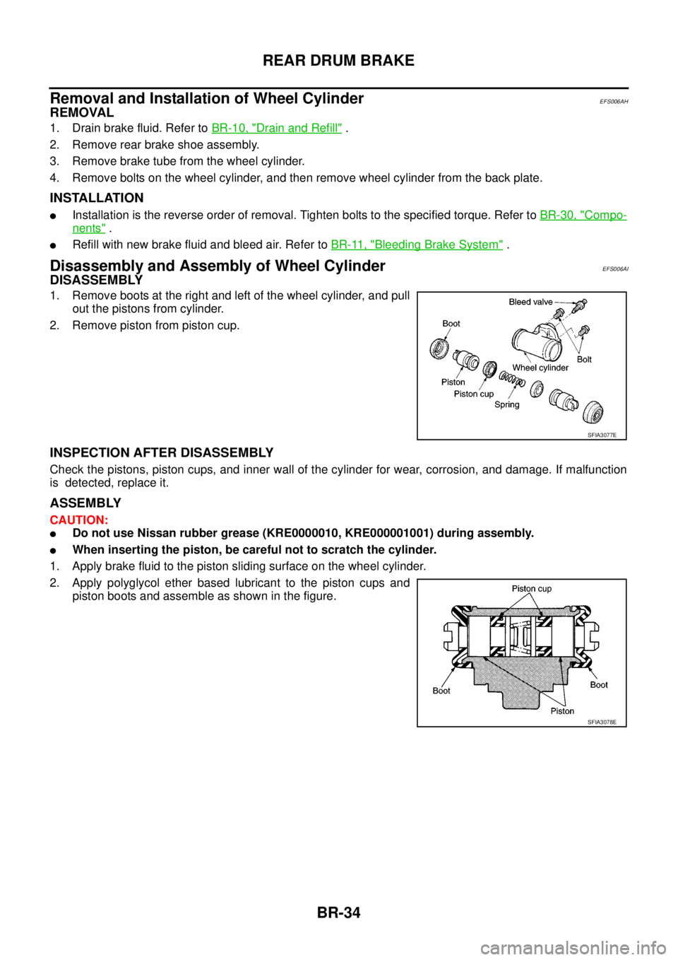
1. Remove boots at the right and left of the wheel cylinder, and pull
out the pistons from cylinder.
2. Remove piston from piston cup.
INSPECTION AFTER DISASSEMBLY
Check the pistons, piston cups, and inner wall of the cylinder for wear, corrosion, and damage. If malfunction
is detected, replace it.
ASSEMBLY
CAUTION:
lDo not use Nissan rubber grease (KRE0000010, KRE000001001) during assembly.
lWhen inserting the piston, be careful not to scratch the cylinder.
1. Apply brake fluid to the piston sliding surface on the wheel cylinder.
2. Apply polyglycol ether based lubricant to the piston cups and
piston boots and assemble as shown in the figure.
SFIA3077E
SFIA3078E
Page 1535 of 3171
PREPARATION
FAX-3
C
E
F
G
H
I
J
K
L
MA
B
FA X
PREPARATIONPFP:00002
Special Service ToolsEDS003I4
Commercial Service ToolsEDS003I5
Tool number
Tool nameDescription
ST29020001
Gear arm pullerRemoving ball joint for steering knuckle
a: 34 mm (1.34 in)
b: 6.5 mm (0.256 in)
c: 61.5 mm (2.421 in)
KV38105500
ProtectorInstalling drive shaft
a: 40 mm (1.57 in) dia
KV40107300
BootbandcrimpingtoolInstalling boot bands
NT694
ZZA0835D
ZZA1229D
Tool nameDescription
PullerRemoving drive shaft
NT077
Page 1539 of 3171
DRIVE SHAFT
FAX-7
C
E
F
G
H
I
J
K
L
MA
B
FA X
DRIVE SHAFTPFP:39100
Removal and InstallationEDS003I9
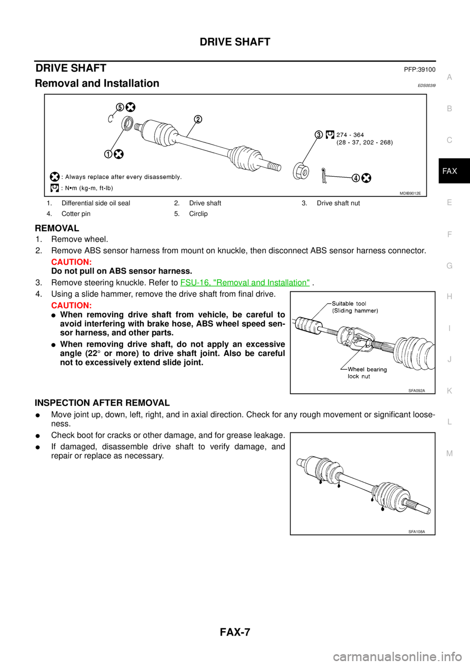
REMOVAL
1. Remove wheel.
2. Remove ABS sensor harness from mount on knuckle, then disconnect ABS sensor harness connector.
CAUTION:
Do not pull on ABS sensor harness.
3. Remove steering knuckle. Refer toFSU-16, "
Removal and Installation".
4. Using a slide hammer, remove the drive shaft from final drive.
CAUTION:
lWhen removing drive shaft from vehicle, be careful to
avoid interfering with brake hose, ABS wheel speed sen-
sor harness, and other parts.
lWhen removing drive shaft, do not apply an excessive
angle (22°or more) to drive shaft joint. Also be careful
not to excessively extend slide joint.
INSPECTION AFTER REMOVAL
lMove joint up, down, left, right, and in axial direction. Check for any rough movement or significant loose-
ness.
lCheck boot for cracks or other damage, and for grease leakage.
lIf damaged, disassemble drive shaft to verify damage, and
repair or replace as necessary.
1. Differential side oil seal 2. Drive shaft 3. Drive shaft nut
4. Cotter pin 5. Circlip
MDIB9012E
SFA092A
SFA108A
Page 1540 of 3171
FAX-8
DRIVE SHAFT
INSTALLATION
Installation is in the reverse order of removal.
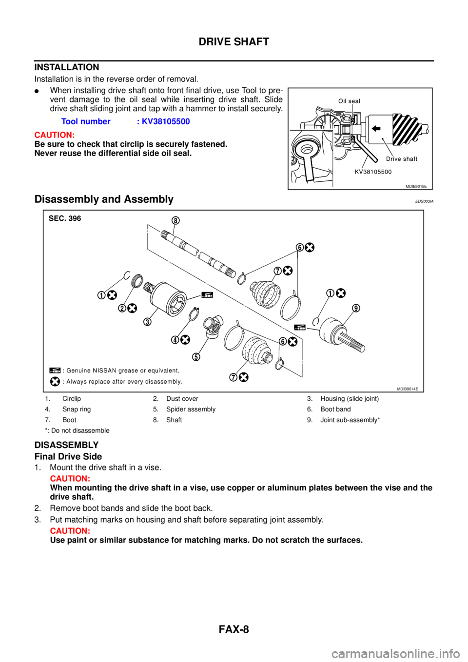
lWhen installing drive shaft onto front final drive, use Tool to pre-
vent damage to the oil seal while inserting drive shaft. Slide
drive shaft sliding joint and tap with a hammer to install securely.
CAUTION:
Be sure to check that circlip is securely fastened.
Never reuse the differential side oil seal.
Disassembly and AssemblyEDS003IA
DISASSEMBLY
Final Drive Side
1. Mount the drive shaft in a vise.
CAUTION:
When mounting the drive shaft in a vise, use copper or aluminum plates between the vise and the
drive shaft.
2. Remove boot bands and slide the boot back.
3. Put matching marks on housing and shaft before separating joint assembly.
CAUTION:
Use paint or similar substance for matching marks. Do not scratch the surfaces.Tool number : KV38105500
MDIB9015E
1. Circlip 2. Dust cover 3. Housing (slide joint)
4. Snap ring 5. Spider assembly 6. Boot band
7. Boot 8. Shaft 9. Joint sub-assembly*
*: Do not disassemble
MDIB9014E
Page 1541 of 3171
DRIVE SHAFT
FAX-9
C
E
F
G
H
I
J
K
L
MA
B
FA X
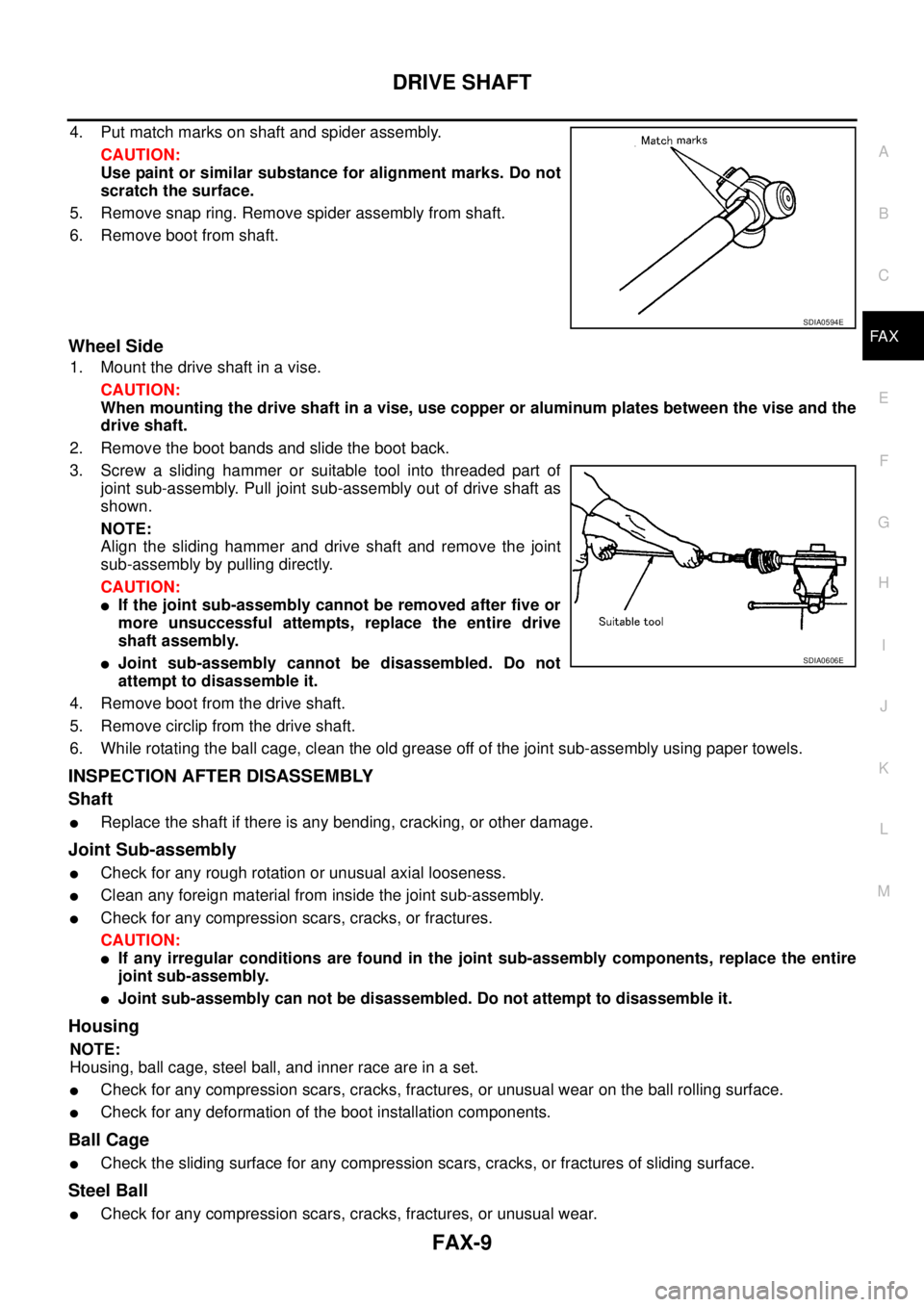
4. Put match marks on shaft and spider assembly.
CAUTION:
Use paint or similar substance for alignment marks. Do not
scratch the surface.
5. Remove snap ring. Remove spider assembly from shaft.
6. Remove boot from shaft.
Wheel Side
1. Mount the drive shaft in a vise.
CAUTION:
When mounting the drive shaft in a vise, use copper or aluminum plates between the vise and the
drive shaft.
2. Remove the boot bands and slide the boot back.
3. Screw a sliding hammer or suitable tool into threaded part of
joint sub-assembly. Pull joint sub-assembly out of drive shaft as
shown.
NOTE:
Align the sliding hammer and drive shaft and remove the joint
sub-assembly by pulling directly.
CAUTION:
lIf the joint sub-assembly cannot be removed after five or
more unsuccessful attempts, replace the entire drive
shaft assembly.
lJoint sub-assembly cannot be disassembled. Do not
attempt to disassemble it.
4. Remove boot from the drive shaft.
5. Remove circlip from the drive shaft.
6. While rotating the ball cage, clean the old grease off of the joint sub-assembly using paper towels.
INSPECTION AFTER DISASSEMBLY
Shaft
lReplace the shaft if there is any bending, cracking, or other damage.
Joint Sub-assembly
lCheck for any rough rotation or unusual axial looseness.
lClean any foreign material from inside the joint sub-assembly.
lCheck for any compression scars, cracks, or fractures.
CAUTION:
lIf any irregular conditions are found in the joint sub-assembly components, replace the entire
joint sub-assembly.
lJoint sub-assembly can not be disassembled. Do not attempt to disassemble it.
Housing
NOTE:
Housing, ball cage, steel ball, and inner race are in a set.
lCheck for any compression scars, cracks, fractures, or unusual wear on the ball rolling surface.
lCheck for any deformation of the boot installation components.
Ball Cage
lCheck the sliding surface for any compression scars, cracks, or fractures of sliding surface.
Steel Ball
lCheck for any compression scars, cracks, fractures, or unusual wear.
SDIA0594E
SDIA0606E
Page 1542 of 3171
FAX-10
DRIVE SHAFT
Inner Race
lCheck the ball sliding surface for any compression scars, cracks, or fractures.
lCheck for any damage to the serrated part.
ASSEMBLY
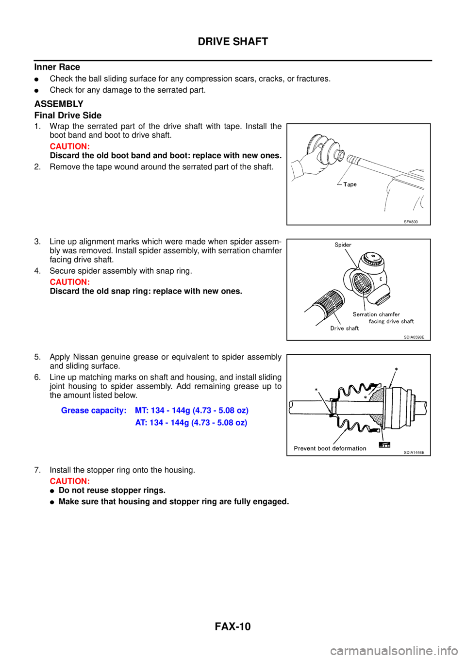
Final Drive Side
1. Wrap the serrated part of the drive shaft with tape. Install the
boot band and boot to drive shaft.
CAUTION:
Discard the old boot band and boot: replace with new ones.
2. Remove the tape wound around the serrated part of the shaft.
3. Line up alignment marks which were made when spider assem-
bly was removed. Install spider assembly, with serration chamfer
facing drive shaft.
4. Secure spider assembly with snap ring.
CAUTION:
Discard the old snap ring: replace with new ones.
5. Apply Nissan genuine grease or equivalent to spider assembly
and sliding surface.
6. Line up matching marks on shaft and housing, and install sliding
joint housing to spider assembly. Add remaining grease up to
the amount listed below.
7. Install the stopper ring onto the housing.
CAUTION:
lDo not reuse stopper rings.
lMake sure that housing and stopper ring are fully engaged.
SFA800
SDIA0598E
Grease capacity: MT: 134 - 144g (4.73 - 5.08 oz)
AT: 134 - 144g (4.73 - 5.08 oz)
SDIA1446E
Page 1543 of 3171
DRIVE SHAFT
FAX-11
C
E
F
G
H
I
J
K
L
MA
B
FA X
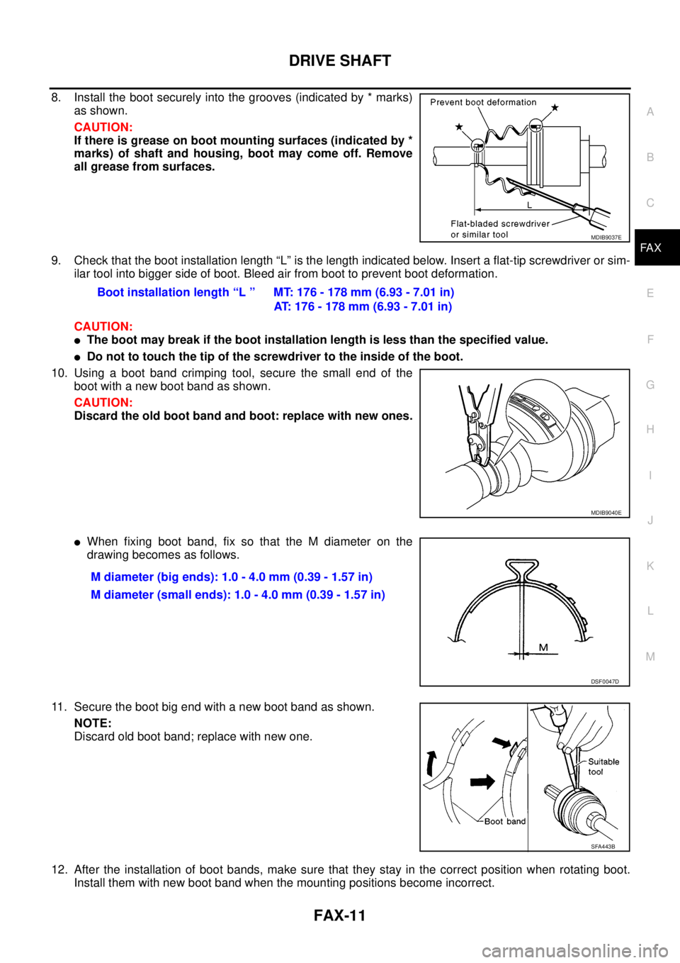
8. Install the boot securely into the grooves (indicated by * marks)
as shown.
CAUTION:
If there is grease on boot mounting surfaces (indicated by *
marks) of shaft and housing, boot may come off. Remove
all grease from surfaces.
9. Check that the boot installation length “L” is the length indicated below. Insert a flat-tip screwdriver or sim-
ilar tool into bigger side of boot. Bleed air from boot to prevent boot deformation.
CAUTION:
lThe boot may break if the boot installation length is less than the specified value.
lDo not to touch the tip of the screwdriver to the inside of the boot.
10. Usingabootbandcrimpingtool,securethesmallendofthe
boot with a new boot band as shown.
CAUTION:
Discard the old boot band and boot: replace with new ones.
lWhen fixing boot band, fix so that the M diameter on the
drawing becomes as follows.
11. Secure the boot big end with a new boot band as shown.
NOTE:
Discard old boot band; replace with new one.
12. After the installation of boot bands, make sure that they stay in the correct position when rotating boot.
Install them with new boot band when the mounting positions become incorrect.
MDIB9037E
Boot installation length “L ” MT: 176 - 178 mm (6.93 - 7.01 in)
AT: 176 - 178 mm (6.93 - 7.01 in)
MDIB9040E
M diameter (big ends): 1.0 - 4.0 mm (0.39 - 1.57 in)
M diameter (small ends): 1.0 - 4.0 mm (0.39 - 1.57 in)
DSF0047D
SFA443B
Page 1544 of 3171
FAX-12
DRIVE SHAFT
13. Install circlip and dust cover to housing.
NOTE:
Do not reuse circlip and dust cover.
Wheel Side
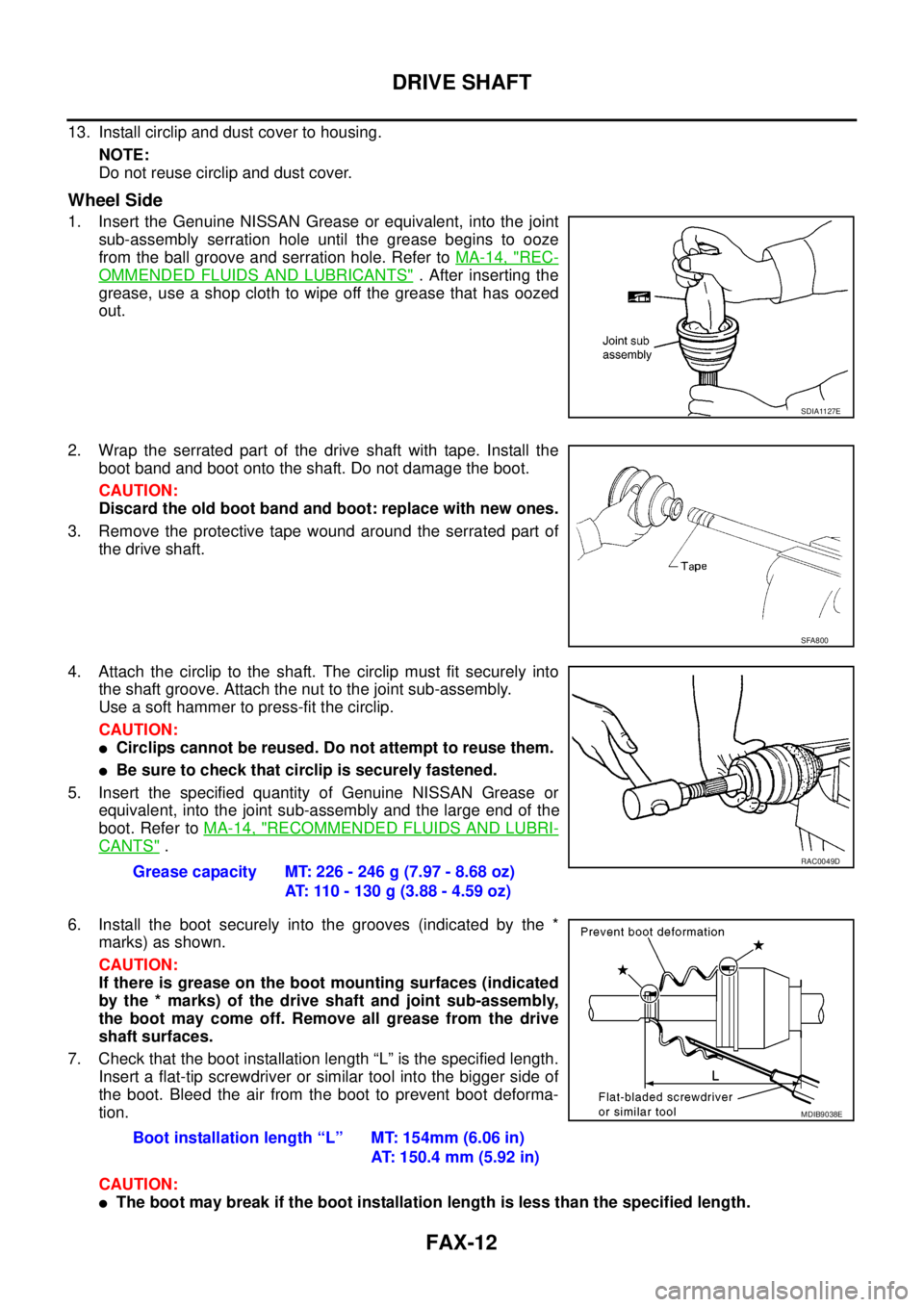
1. Insert the Genuine NISSAN Grease or equivalent, into the joint
sub-assembly serration hole until the grease begins to ooze
from the ball groove and serration hole. Refer toMA-14, "
REC-
OMMENDED FLUIDS AND LUBRICANTS". After inserting the
grease, use a shop cloth to wipe off the grease that has oozed
out.
2. Wrap the serrated part of the drive shaft with tape. Install the
boot band and boot onto the shaft. Do not damage the boot.
CAUTION:
Discard the old boot band and boot: replace with new ones.
3. Remove the protective tape wound around the serrated part of
the drive shaft.
4. Attach the circlip to the shaft. The circlip must fit securely into
the shaft groove. Attach the nut to the joint sub-assembly.
Useasofthammertopress-fitthecirclip.
CAUTION:
lCirclips cannot be reused. Do not attempt to reuse them.
lBe sure to check that circlip is securely fastened.
5. Insert the specified quantity of Genuine NISSAN Grease or
equivalent, into the joint sub-assembly and the large end of the
boot. Refer toMA-14, "
RECOMMENDED FLUIDS AND LUBRI-
CANTS".
6. Install the boot securely into the grooves (indicated by the *
marks) as shown.
CAUTION:
If there is grease on the boot mounting surfaces (indicated
by the * marks) of the drive shaft and joint sub-assembly,
the boot may come off. Remove all grease from the drive
shaft surfaces.
7. Check that the boot installation length “L” is the specified length.
Insert a flat-tip screwdriver or similar tool into the bigger side of
the boot. Bleed the air from the boot to prevent boot deforma-
tion.
CAUTION:
lThe boot may break if the boot installation length is less than the specified length.
SDIA1127E
SFA800
Grease capacity MT: 226 - 246 g (7.97 - 8.68 oz)
AT: 110 - 130 g (3.88 - 4.59 oz)RAC0049D
Boot installation length “L” MT: 154mm (6.06 in)
AT: 150.4 mm (5.92 in)
MDIB9038E