Page 1545 of 3171
DRIVE SHAFT
FAX-13
C
E
F
G
H
I
J
K
L
MA
B
FA X
lDo not contact inside surface of boot with the tip of the screwdriver.
8. Secure small end of the boot using a new boot band and a boot
band crimping tool as shown.
CAUTION:
Discard the old boot band and boot: replace with new ones.
lWhen fixing boot band, fix so that the M diameter on the
drawing becomes as follows.
9. Secure the boot big end with a new boot band as shown.
NOTE:
Discard old boot band; replace with new one.
10. After the installation of boot bands, rotate the boot to check that
it is positioned correctly. If the boot is not positioned correctly,
remove the old boot bands then reposition the boot and secure
the boot with new boot bands.Tool number : KV40107300
MDIB9040E
M diameter (big ends): 1.0 - 4.0 mm (0.39 - 1.57 in)
M diameter (small ends): 1.0 - 4.0 mm (0.39 - 1.57 in)
DSF0047D
SFA443B
Page 1546 of 3171
FAX-14
SERVICE DATA AND SPECIFICATIONS (SDS)
SERVICE DATA AND SPECIFICATIONS (SDS)
PFP:00030
Wheel BearingEDS003IB
Drive ShaftEDS003IC
Wheel bearing axial end play 0.05 mm (0.002 in) or less
Wheel Side Final Drive Side
Applied modelEngine YD25, VQ40
Transaxle MT AT
Drive shaft joint type Final drive side AAR3300I AAR3300I
Wheel side UF3700I AC3300I
GreaseQuality Nissan genuine grease or equivalent
Capacity g (oz)Final drive side 134 - 144 (4.73 - 5.08) 134 - 144 (4.73 - 5.08)
Wheel side 226 - 246 (7.97 - 8.68) 110 - 130 (3.88 - 4.59)
Boot length “L” mm (in)Final drive side 176 - 178 (6.93 - 7.01) 176 - 178 (6.93 - 7.01)
Wheel side 154 (6.06) 150.4 (5.92)
MDIB9038EMDIB9037E
Page 1617 of 3171

KNUCKLE
FSU-17
C
D
F
G
H
I
J
K
L
MA
B
FSU
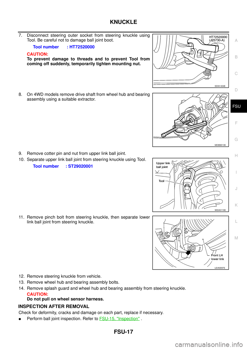
7. Disconnect steering outer socket from steering knuckle using
Tool. Be careful not to damage ball joint boot.
CAUTION:
To prevent damage to threads and to prevent Tool from
coming off suddenly, temporarily tighten mounting nut.
8. On 4WD models remove drive shaft from wheel hub and bearing
assembly using a suitable extractor.
9. Remove cotter pin and nut from upper link ball joint.
10. Separate upper link ball joint from steering knuckle using Tool.
11. Remove pinch bolt from steering knuckle, then separate lower
link ball joint from steering knuckle.
12. Remove steering knuckle from vehicle.
13. Remove wheel hub and bearing assembly bolts.
14. Remove splash guard and wheel hub and bearing assembly from steering knuckle.
CAUTION:
Do not pull on wheel sensor harness.
INSPECTION AFTER REMOVAL
Check for deformity, cracks and damage on each part, replace if necessary.
lPerform ball joint inspection. Refer toFSU-15, "Inspection". Tool number : HT72520000
SDIA1434E
MDIB9013E
Tool number : ST29020001
WEIA0119E
LEIA0097E
Page 1632 of 3171

GI-10
HOW TO USE THIS MANUAL
Components
EAS001GW
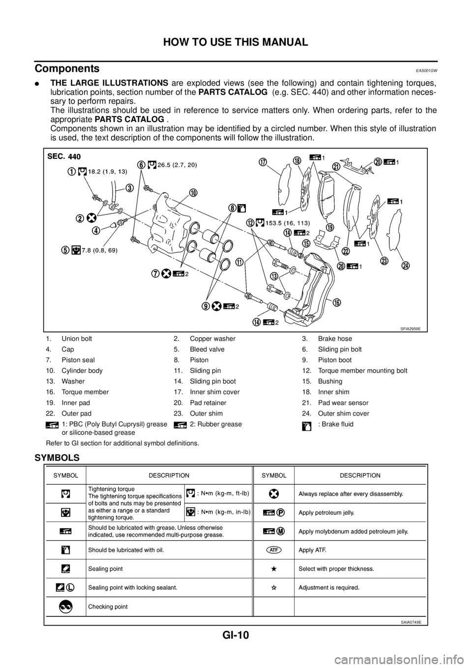
lTHE LARGE ILLUSTRATIONSare exploded views (see the following) and contain tightening torques,
lubrication points, section number of thePARTS CATALOG(e.g. SEC. 440) and other information neces-
sary to perform repairs.
The illustrations should be used in reference to service matters only. When ordering parts, refer to the
appropriatePARTS CATALOG.
Components shown in an illustration may be identified by a circled number. When this style of illustration
is used, the text description of the components will follow the illustration.
SYMBOLS
1. Union bolt 2. Copper washer 3. Brake hose
4. Cap 5. Bleed valve 6. Sliding pin bolt
7. Piston seal 8. Piston 9. Piston boot
10. Cylinder body 11. Sliding pin 12. Torque member mounting bolt
13. Washer 14. Sliding pin boot 15. Bushing
16. Torque member 17. Inner shim cover 18. Inner shim
19. Inner pad 20. Pad retainer 21. Pad wear sensor
22. Outer pad 23. Outer shim 24. Outer shim cover
1: PBC (Poly Butyl Cuprysil) grease
or silicone-based grease2: Rubber grease : Brake fluid
Refer to GI section for additional symbol definitions.
SFIA2959E
SAIA0749E
Page 1760 of 3171

IP-1
INSTRUMENT PANEL
IBODY
CONTENTS
C
D
E
F
G
H
J
K
L
M
SECTIONIP
A
B
IP
INSTRUMENT PANEL
PRECAUTIONS .......................................................... 2
Precautions for Supplemental Restraint System
(SRS)“AIRBAG”and“SEATBELTPRE-TEN-
SIONER” .................................................................. 2
Precautions for SRS “AIR BAG” and “SEAT BELT
PRE-TENSIONER” Service ..................................... 2
PREPARATION ........................................................... 3
Commercial Service Tools ........................................ 3
SQUEAK AND RATTLE TROUBLE DIAGNOSES..... 4
Work Flow ................................................................ 4
CUSTOMER INTERVIEW ..................................... 4
DUPLICATE THE NOISE AND TEST DRIVE ....... 5
CHECK RELATED SERVICE BULLETINS ........... 5
LOCATE THE NOISE AND IDENTIFY THE
ROOT CAUSE ...................................................... 5
REPAIR THE CAUSE ........................................... 5
CONFIRM THE REPAIR ....................................... 5
Generic Squeak and Rattle Troubleshooting ........... 6
INSTRUMENT PANEL .......................................... 6
CENTER CONSOLE ............................................. 6
DOORS ................................................................. 6TRUNK .................................................................. 6
SUNROOF/HEADLINING ..................................... 7
OVERHEAD CONSOLE (FRONT AND REAR)..... 7
SEATS ................................................................... 7
UNDERHOOD ....................................................... 7
Diagnostic Worksheet ............................................... 8
INSTRUMENT PANEL ASSEMBLY ......................... 10
Removal and Installation ........................................ 10
INSTRUMENT PANEL ........................................ 10
CLUSTER LID C ................................................. 11
CLUSTER LID D ................................................. 12
LOWER INSTRUMENT PANEL LH ..................... 13
COMBINATION METER ...................................... 13
A/T CONTROL FINISHER (A/T) .......................... 14
CONSOLE BOOT M/T ........................................ 14
LOWER INSTRUMENT PANEL RH AND GLOVE
BOX ..................................................................... 15
CENTER CONSOLE ........................................... 16
Disassembly and Assembly .................................... 17
CENTER CONSOLE ........................................... 17
Page 1771 of 3171
IP-12
INSTRUMENT PANEL ASSEMBLY
Removal - with NAVI
1. Remove A/T control finisher, or console boot M/T. Refer toIP-14, "A/T CONTROL FINISHER (A/T)",or
Refer toIP-14, "
CONSOLE BOOT M/T".
2. Pull cluster lid C rearward to release clips.
3. Disconnect electrical connectors and remove cluster lid C.
Installation - with NAVI
Installation is in the reverse order of removal.
CLUSTER LID D
Removal
1. Remove center console. Refer toIP-16, "CENTER CONSOLE".
2. Remove lower instrument panel LH. Refer toIP-13, "
LOWER INSTRUMENT PANEL LH".
3. Remove glove box lower. Refer toIP-15, "
LOWER INSTRUMENT PANEL RH AND GLOVE BOX".
4. Disconnect the electrical connectors and remove cluster lid D.
Installation
Installation is in the reverse order of removal.
1. Instrument panel 2. Cluster lid C
MIIB9079E
WIIA0564E
1. Cluster lid D 2. Screws
Page 1773 of 3171
IP-14
INSTRUMENT PANEL ASSEMBLY
A/T CONTROL FINISHER (A/T)
1. Remove cup holder finisher.
2. Remove finisher, from A/T control finisher.
3. Pull up to release clips and remove the A/T finisher.
Installation
Installation is in the reverse order of removal.
CONSOLE BOOT M/T
1. Remove cup holder finisher.
2. Remove M/T finisher bezel.
3. Pull up to release clips and remove the M/T finisher.
Installation
Installation is in the reverse order of removal.
LIIA1941E
LIIA1942E
Page 2313 of 3171
MA-38
CHASSIS AND BODY MAINTENANCE
Checking Axle and Suspension Parts
ELS001J5
FRONT AND REAR AXLE AND SUSPENSION PARTS
Check front and rear axle and suspension parts for excessive play, cracks, wear or other damage.
lShake each wheel to check for excessive play.
lRotate each wheel to check for abnormal noise.
lCheck axle and suspension nuts and bolts for looseness.
lCheck the strut and shock absorber for oil leakage or other damage.
lCheck suspension ball joints for grease leakage and ball joint dust cover for cracks or other damage.
FRONT DRIVE SHAFT
Check the boots and drive shaft for cracks, wear, damage, and
grease leakage.
SMA525A
SFA901