Page 501 of 3171
SYSTEM DESCRIPTION
AV-13
C
D
E
F
G
H
I
J
L
MA
B
AV
Wiring Diagram — AUDIO — / With 1CD Player TypeEKS00Q62
MKWA3600E
Page 504 of 3171
AV-16
SYSTEM DESCRIPTION
Schematic — AUDIO — / With 6CD Player Type
EKS00Q63
MKWA3603E
Page 505 of 3171
SYSTEM DESCRIPTION
AV-17
C
D
E
F
G
H
I
J
L
MA
B
AV
Wiring Diagram — AUDIO — / With 6CD Player TypeEKS00Q64
MKWA3604E
Page 522 of 3171
AV-34
TERMINALS AND REFERENCE VALUE FOR CONTROL UNIT
TERMINALS AND REFERENCE VALUE FOR CONTROL UNIT
PFP:00000
Audio Unit (1CD Player Type)EKS00Q6B
Te r m i n a l
(Wire color)
ItemSignal
input/
outputCondition
Reference value
+-Ignition
switchOperation
2
(O)Ground Illumination signal Input ONLighting switch is ON. Approx. 12 V
Lighting switch is OFF. Approx. 0 V
3
(Y)Ground Battery power supply Input ON – Battery voltage
4
(Y)–TELmute – – – –
6
(V)Ground ACC power supply Input ACC – Battery voltage
7
(BR)5
(L)Audio signal front LH Output ON Sound output
8
(W)GroundVehicle speed signal
(2-pulse)Input ONWhen vehicle speed is
approx. 40 km/h (25
MPH).
9
(L)10
(V)Audio signal rear LH Output ON Sound output
12
(SB)– Immobilizer – – – –
13
(LG)11
(V)Audio signal front RH Output ON Sound output
15
(GR)16
(V)Audio signal rear RH Output ON Sound output
19
(W)–TELin(-) – – – –
SKIB1990E
ELF1080D
SKIB1990E
SKIB1990E
SKIB1990E
Page 523 of 3171

TERMINALS AND REFERENCE VALUE FOR CONTROL UNIT
AV-35
C
D
E
F
G
H
I
J
L
MA
B
AV
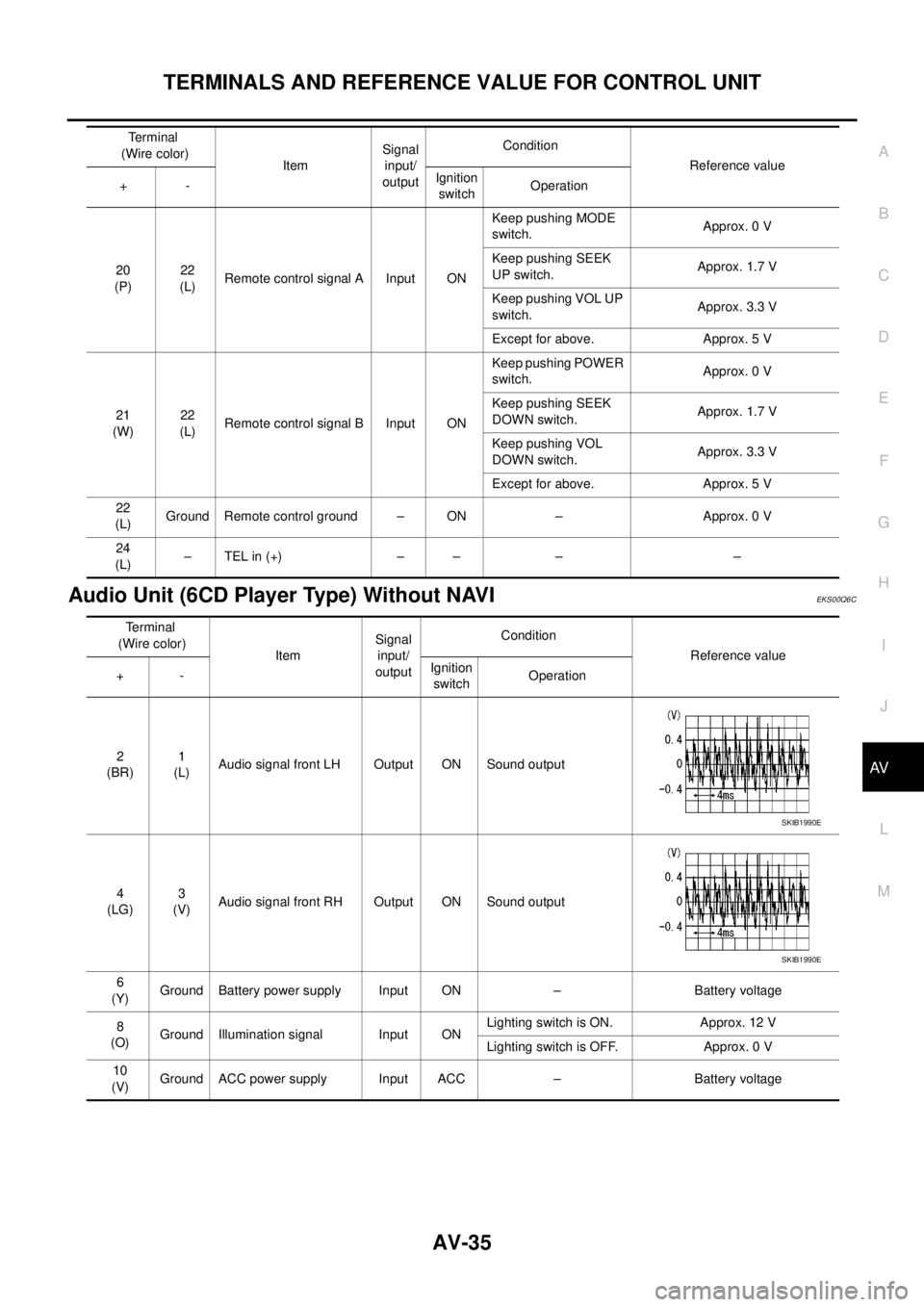
Audio Unit (6CD Player Type) Without NAVIEKS00Q6C
20
(P)22
(L)Remote control signal A Input ONKeep pushing MODE
switch.Approx. 0 V
Keep pushing SEEK
UP switch.Approx. 1.7 V
Keep pushing VOL UP
switch.Approx. 3.3 V
Except for above. Approx. 5 V
21
(W)22
(L)Remote control signal B Input ONKeep pushing POWER
switch.Approx. 0 V
Keep pushing SEEK
DOWN switch.Approx. 1.7 V
Keep pushing VOL
DOWN switch.Approx. 3.3 V
Except for above. Approx. 5 V
22
(L)Ground Remote control ground – ON – Approx. 0 V
24
(L)–TELin(+) – – – – Terminal
(Wire color)
ItemSignal
input/
outputCondition
Reference value
+-Ignition
switchOperation
Terminal
(Wire color)
ItemSignal
input/
outputCondition
Reference value
+-Ignition
switchOperation
2
(BR)1
(L)Audio signal front LH Output ON Sound output
4
(LG)3
(V)Audio signal front RH Output ON Sound output
6
(Y)Ground Battery power supply Input ON – Battery voltage
8
(O)Ground Illumination signal Input ONLighting switch is ON. Approx. 12 V
Lighting switch is OFF. Approx. 0 V
10
(V)Ground ACC power supply Input ACC – Battery voltage
SKIB1990E
SKIB1990E
Page 524 of 3171
AV-36
TERMINALS AND REFERENCE VALUE FOR CONTROL UNIT
14
(L)13
(V)Audio signal rear LH Output ON Sound output
16
(GR)15
(V)Audio signal rear RH Output ON Sound output
18
(W)GroundVehicle speed signal
(2-pulse)Input ONWhen vehicle speed is
approx. 40 km/h (25
MPH).
20
(SB)– Immobilizer – – – –
22
(P)25
(L)Remote control signal A Input ONKeep pushing MODE
switch.Approx. 0 V
Keep pushing SEEK UP
switch.Approx. 1.7 V
Keep pushing VOL UP
switch.Approx. 3.3 V
Except for above. Approx. 5 V
23
(W)25
(L)Remote control signal B Input ONKeep pushing POWER
switch.Approx. 0 V
Keep pushing SEEK
DOWN switch.Approx. 1.7 V
Keep pushing VOL
DOWN switch.Approx. 3.3 V
Except for above. Approx. 5V
25
(L)Ground Remote control ground – ON – Approx. 0 V
26
(W)–TELin(–) – – – –
27
(L)–TELin(+) – – – –
28
(Y)–TELmute – – – – Terminal
(Wire color)
ItemSignal
input/
outputCondition
Reference value
+-Ignition
switchOperation
SKIB1990E
SKIB1990E
ELF1080D
Page 525 of 3171

TERMINALS AND REFERENCE VALUE FOR CONTROL UNIT
AV-37
C
D
E
F
G
H
I
J
L
MA
B
AV
Audio Unit (With NAVI)EKS00Q6D
Terminal
(Wire color)
ItemSignal
input/
outputCondition
Reference value
+-Ignition
switchOperation
3
(Y)–Communication
signal (H)Input/
output–– –
4
(R)–Communication
signal (L)Input/
output–– –
10
(W)11
(O)TEL voice signal Input ON TEL voice output
12
(O)13
(W)Voice guidance signal Input ON Voice guidance output
17 Ground Shield (TEL voice) – ON – Approx. 0 V
18 Ground Shield (Guide voice) – ON – Approx. 0 V
22
(BR)23
(L)Audio signal front LH Output ON Sound output
24
(L)25
(V)Audio signal rear LH Output ON Sound output
26
(P)35
(L)Remote control signal A Input ONKeep pushing SOURCE
switch.approx. 0 V
Keep pushing MENU
UP switch.Approx. 1.2 V
Keep pushing MENU
DOWN switch.Approx. 2.5 V
Keep pushing ENTER
switch.Approx. 3.7 V
Except for above. Approx. 5 V
27
(V)Ground ACC power supply Input ACC – Battery voltage
28
(B)GroundIllumination control sig-
nalInput ONIllumination control
switch is operated by
lighting switch in ON
positionChanges between approx. 0 V
and approx. 12 V
SKIB1990E
SKIB1990E
SKIB1990E
SKIB1990E
Page 526 of 3171

AV-38
TERMINALS AND REFERENCE VALUE FOR CONTROL UNIT
NAVI Control Unit
EKS00Q6E
29
(O)Ground Illumination signal Input ONLighting switch is ON. Approx. 12 V
Lighting switch is OFF. Approx. 0 V
31
(LG)32
(V)Audio signal front RH Output ON Sound output
33
(GR)34
(V)Audio signal rear RH Output ON Sound output
36
(W)35
(L)Remote control signal B Input ONKeep pushing VOL
DOWN switch.Approx. 0 V
Keep pushing VOL UP
switch.Approx. 1.2 V
Keep pushing TEL, PTT
switch.Approx. 2.5 V
Keep pushing BACK
switch.Approx. 3.7 V
Except for above. Approx. 5 V
39
(Y)Ground Battery power supply Input ON – Battery voltage Terminal
(Wire color)
ItemSignal
input/
outputCondition
Reference value
+-Ignition
switchOperation
SKIB1990E
SKIB1990E
Terminal
(Wire color)
ItemSignal
input/
outputCondition
Reference value
+-Ignition
switchOperation
1
(B)Ground Ground – ON – Approx. 0 V
2
(Y)Ground Battery power supply Input ON – Battery voltage
5
(V)Ground ACC power supply Input ACC – Battery voltage
6
(B)Ground MIC. power supply Output ON – Approx. 5 V
7 Ground Shield (MIC.) – ON – Approx. 0 V
8
(W)Ground MIC. signal Input ON Sounds
9 Ground Shield (TEL voice) – ON – Approx. 0 V
PKIB5037J