2005 NISSAN NAVARA audio
[x] Cancel search: audioPage 549 of 3171

TROUBLE DIAGNOSIS
AV-61
C
D
E
F
G
H
I
J
L
MA
B
AV
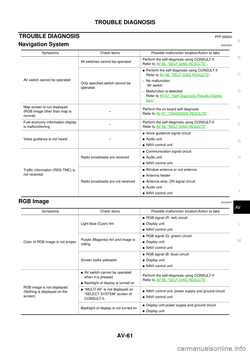
TROUBLE DIAGNOSISPFP:00004
Navigation SystemEKS00Q6O
RGB ImageEKS00Q6P
Symptoms Check items Possible malfunction location/Action to take
AV switch cannot be operatedAll switches cannot be operatedPerform the self-diagnosis using CONSULT-II
Refer toAV-56, "
SELF-DIAG RESULTS".
Only specified switch cannot be
operated
lPerform the self-diagnosis using CONSULT-II
Refer toAV-56, "
SELF-DIAG RESULTS".
–No malfunction
AV switch
–Malfunction is detected
Refer toAV-57, "
Self-Diagnostic Results Display
Item".
Map screen is not displayed
(RGB image other than map is
normal)–Perform the on board self-diagnosis
Refer toAV-47, "
DIAGNOSIS RESULTS".
Fuel economy information display
is malfunctioning–Perform the self-diagnosis using CONSULT-II
Refer toAV-56, "
SELF-DIAG RESULTS".
Voice guidance is not heard. –
lVoice guidance signal circuit
lAudio unit
lNAVI control unit
Traffic information (RDS-TMC) is
not receivedRadio broadcasts are received
lCommunication signal circuit
lAudio unit
lNAVI control unit
Radio broadcasts are not received
lWindow antenna or rod antenna
lAntenna feeder
lAntenna amp. ON signal circuit
lAudio unit
lNAVI control unit
Symptoms Check items Possible malfunction location/Action to take
Color of RGB image is not proper.Light blue (Cyan) tint
lRGB signal (R: red) circuit
lDisplay unit
lNAVI control unit
Purple (Magenta) tint and image is
rolling
lRGB signal (G: green) circuit
lDisplay unit
lNAVI control unit
Screen looks yellowish
lRGB signal (B: blue) circuit
lDisplay unit
lNAVI control unit
RGB image is not displayed
(Nothing is displayed on the
screen)
lAV switch cannot be operated
when it is pressed
lBacklight of display is turned onPerform the self-diagnosis using CONSULT-II
Refer toAV-56, "SELF-DIAG RESULTS".
l“MULTI AV” is not displayed on
“SELECT SYSTEM” screen of
CONSULT-II.lNAVI control unit power supply and ground circuit
lNAVI control unit
Backlight of display is not turned on
lDisplay unit power supply and ground circuit
lDisplay unit
Page 550 of 3171

AV-62
TROUBLE DIAGNOSIS
Voice Activated Control System
EKS00Q6Q
Symptoms Check items Probable malfunction location
The voice cannot be controlled
even if the voice control screen is
displayedVoice sounds at “Speaker Test” and
“Voice Microphone Test” of Confir-
mation/Adjustment modeNAVI control unit
Voice does not sound at “Speaker
Test” and “Voice Microphone Test” of
Confirmation/Adjustment mode
lMIC. power supply circuit
lShield (MIC.) circuit
lMIC. signal circuit
lMicrophone
lNAVI control unit
The voice cannot be controlled
(Voice control screen is not dis-
played)TEL operation screen is displayed by
pressing and holding “TEL/PPT”
switch of steering wheel switchNAVI control unit
lTEL operation screen is not dis-
played by pressing and holding
“TEL/PPT” switch of steering
wheel switch
lOther steering wheel switches are
normalSteering wheel switch
“BACK”, “VOL UP”, “VOL DOWN”,
and “TEL/PPT” switches of steering
wheel switch are not operated
lRemote control signal B circuit
lSteering wheel switch
lAudio unit
All steering wheel switches are not
operated
lRemote control signal ground circuit
lSteering wheel switch
lAudio unit
Page 551 of 3171

TROUBLE DIAGNOSIS
AV-63
C
D
E
F
G
H
I
J
L
MA
B
AV
Steering Wheel SwitchEKS00Q6R
Without NAVI
With NAVI
Component Parts InspectionEKS00Q6S
STEERING WHEEL SWITCH UNIT INSPECTION
lCheck continuity between combination switch harness connector M302 terminal 15 and terminal 16.
lCheck continuity between combination switch harness connector M302 terminal 14 and terminal 16.
Symptoms Probable malfunction location
All steering wheel switches are not operated
lRemote control signal ground circuit
lSteering wheel switch
lAudio unit
Only specified switch cannot be operated Steering wheel switch
“MODE”, “SEEK UP”, and “VOL UP” switches are not oper-
ated
lRemote control signal A circuit
lSteering wheel switch
lAudio unit
“SEEK DOWN”, and “VOL DOWN” switches are not oper-
ated
lRemote control signal B circuit
lSteering wheel switch
lAudio unit
Symptoms Probable malfunction location
All steering wheel switches are not operated
lRemote control signal ground circuit
lSteering wheel switch
lAudio unit
Only specified switch cannot be operated Steering wheel switch
“ENTER”, “MENU UP”, “MENU DOWN”, and “SOURCE”
switches are not operated
lRemote control signal A circuit
lSteering wheel switch
lAudio unit
“BACK”, “TEL /PPT”, “VOL UP”, and “VOL DOWN” switches
are not operated
lRemote control signal B circuit
lSteering wheel switch
lAudio unit
Page 561 of 3171

REMOVAL AND INSTALLATION
AV-73
C
D
E
F
G
H
I
J
L
MA
B
AV
REMOVAL AND INSTALLATIONPFP:00000
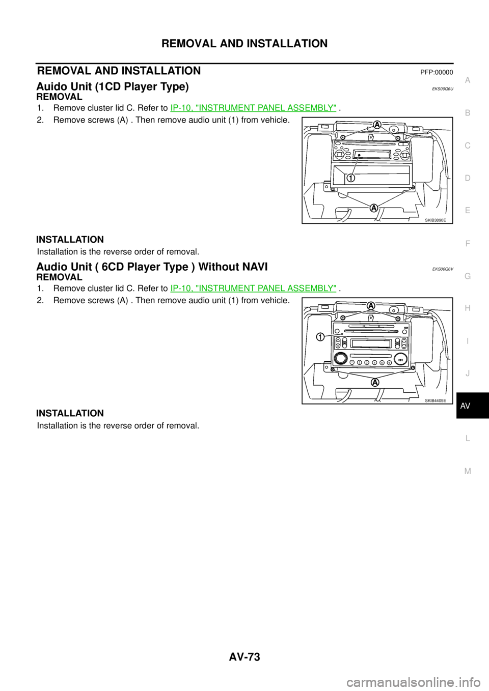
Auido Unit (1CD Player Type)EKS00Q6U
REMOVAL
1. Remove cluster lid C. Refer toIP-10, "INSTRUMENT PANEL ASSEMBLY".
2. Remove screws (A) . Then remove audio unit (1) from vehicle.
INSTALLATION
Installation is the reverse order of removal.
Audio Unit ( 6CD Player Type ) Without NAVIEKS00Q6V
REMOVAL
1. Remove cluster lid C. Refer toIP-10, "INSTRUMENT PANEL ASSEMBLY".
2. Remove screws (A) . Then remove audio unit (1) from vehicle.
INSTALLATION
Installation is the reverse order of removal.
SKIB3890E
SKIB4405E
Page 562 of 3171

AV-74
REMOVAL AND INSTALLATION
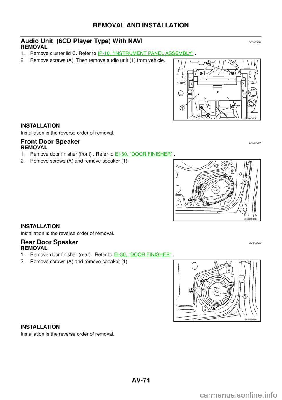
Audio Unit (6CD Player Type) With NAVI
EKS00Q6W
REMOVAL
1. Remove cluster lid C. Refer toIP-10, "INSTRUMENT PANEL ASSEMBLY".
2. Remove screws (A). Then remove audio unit (1) from vehicle.
INSTALLATION
Installation is the reverse order of removal.
Front Door SpeakerEKS00Q6X
REMOVAL
1. Remove door finisher (front) . Refer toEI-30, "DOOR FINISHER".
2. Remove screws (A) and remove speaker (1).
INSTALLATION
Installation is the reverse order of removal.
Rear Door SpeakerEKS00Q6Y
REMOVAL
1. Remove door finisher (rear) . Refer toEI-30, "DOOR FINISHER".
2. Remove screws (A) and remove speaker (1).
INSTALLATION
Installation is the reverse order of removal.
SKIB4580E
SKIB3905E
SKIB3906E
Page 564 of 3171

AV-76
REMOVAL AND INSTALLATION
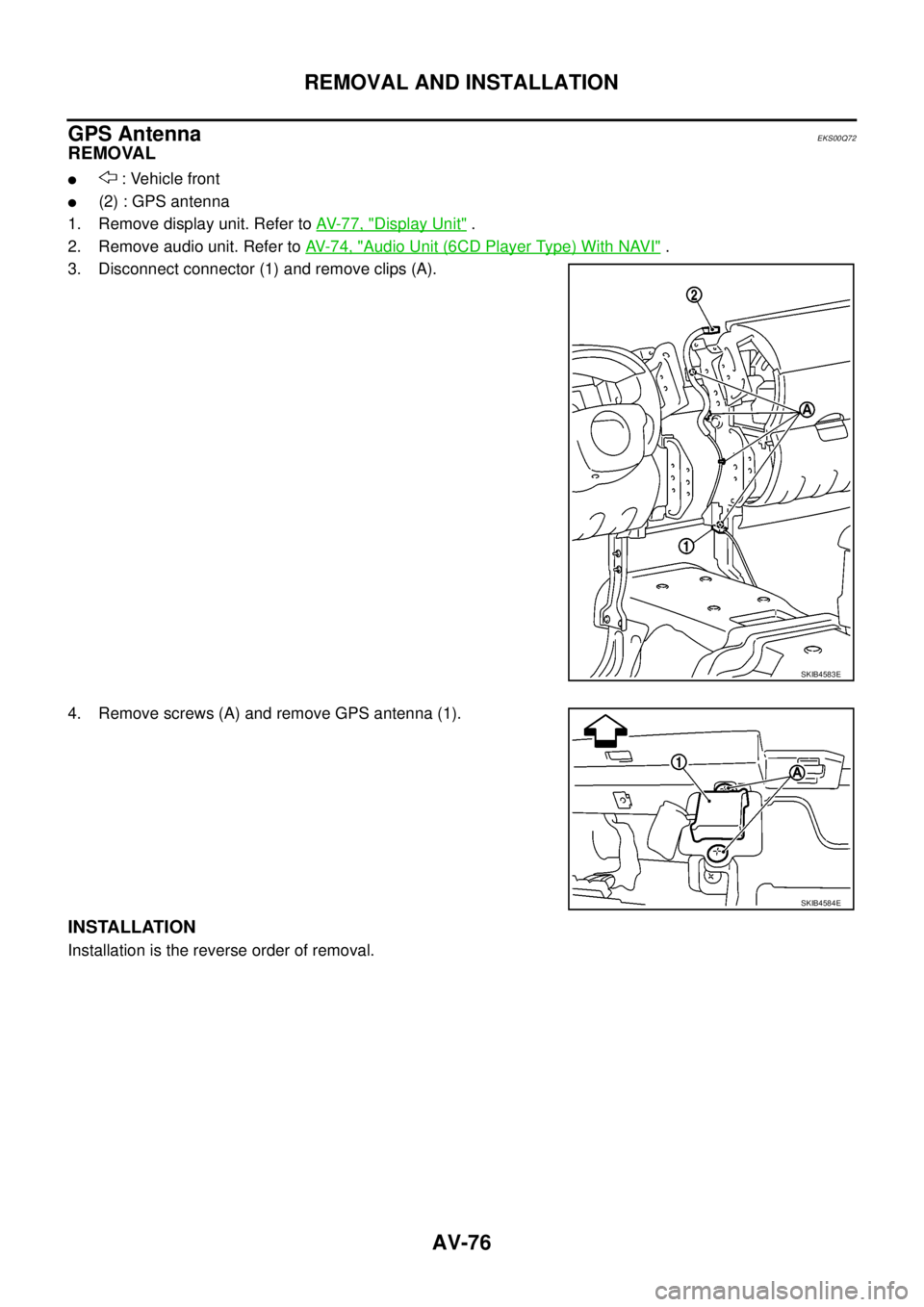
GPS Antenna
EKS00Q72
REMOVAL
l: Vehicle front
l(2) : GPS antenna
1. Remove display unit. Refer toAV-77, "
Display Unit".
2. Remove audio unit. Refer toAV-74, "
Audio Unit (6CD Player Type) With NAVI".
3. Disconnect connector (1) and remove clips (A).
4. Remove screws (A) and remove GPS antenna (1).
INSTALLATION
Installation is the reverse order of removal.
SKIB4583E
SKIB4584E
Page 592 of 3171

BL-8
SQUEAK AND RATTLE TROUBLE DIAGNOSES
FELT CLOTHTAPE
Used to insulate where movement does not occur. Ideal for instrument panel applications.
68370-4B000: 15´25 mm (0.59´0.98 in) pad/68239-13E00: 5 mm (0.20 in) wide tape roll
The following materials, not available through NISSAN Parts Department, can also be used to repair squeaks
and rattles.
UHMW(TEFLON) TAPE
Insulates where slight movement is present. Ideal for instrument panel applications.
SILICONE GREASE
Used in place of UHMW tape that will be visible or not fit.
Note: Will only last a few months.
SILICONE SPRAY
Use when grease cannot be applied.
DUCT TAPE
Use to eliminate movement.
CONFIRM THE REPAIR
Confirm that the cause of a noise is repaired by test driving the vehicle. Operate the vehicle under the same
conditions as when the noise originally occurred. Refer to the notes on the Diagnostic Worksheet.
Generic Squeak and Rattle TroubleshootingEIS00DI3
Refer to Table of Contents for specific component removal and installation information.
INSTRUMENT PANEL
Most incidents are caused by contact and movement between:
1. Cluster lid A and instrument panel
2. Acrylic lens and combination meter housing
3. Instrument panel to front pillar garnish
4. Instrument panel to windshield
5. Instrument panel mounting pins
6. Wiring harnesses behind the combination meter
7. A/C defroster duct and duct joint
These incidents can usually be located by tapping or moving the components to duplicate the noise or by
pressing on the components while driving to stop the noise. Most of these incidents can be repaired by apply-
ing felt cloth tape or silicon spray (in hard to reach areas). Urethane pads can be used to insulate wiring har-
ness.
CAUTION:
Do not use silicone spray to isolate a squeak or rattle. If you saturate the area with silicone, you will
not be able to recheck the repair.
CENTER CONSOLE
Components to pay attention to include:
1. Shifter assembly cover to finisher
2. A/C control unit and cluster lid C
3. Wiring harnesses behind audio and A/C control unit
The instrument panel repair and isolation procedures also apply to the center console.
DOORS
Pay attention to the:
1. Finisher and inner panel making a slapping noise
2. Inside handle escutcheon to door finisher
3. Wiring harnesses tapping
4. Door striker out of alignment causing a popping noise on starts and stops
Tapping or moving the components or pressing on them while driving to duplicate the conditions can isolate
many of these incidents. You can usually insulate the areas with felt cloth tape or insulator foam blocks to
repair the noise.
Page 1346 of 3171

EI-8
SQUEAK AND RATTLE TROUBLE DIAGNOSES
3. Instrument panel to front pillar garnish
4. Instrument panel to windshield
5. Instrument panel mounting pins
6. Wiring harnesses behind the combination meter
7. A/C defroster duct and duct joint
These incidents can usually be located by tapping or moving the components to duplicate the noise or by
pressing on the components while driving to stop the noise. Most of these incidents can be repaired by apply-
ing felt cloth tape or silicone spray (in hard to reach areas). Urethane pads can be used to insulate wiring har-
ness.
CAUTION:
Do not use silicone spray to isolate a squeak or rattle. If you saturate the area with silicone, you will
not be able to recheck the repair.
CENTER CONSOLE
Components to pay attention to include:
1. Shifter assembly cover to finisher
2. A/C control unit and cluster lid C
3. Wiring harnesses behind audio and A/C control unit
The instrument panel repair and isolation procedures also apply to the center console.
DOORS
Pay attention to the:
1. Finisher and inner panel making a slapping noise
2. Inside handle escutcheon to door finisher
3. Wiring harnesses tapping
4. Door striker out of alignment causing a popping noise on starts and stops
Tapping or moving the components or pressing on them while driving to duplicate the conditions can isolate
many of these incidents.
TRUNK
Trunk noises are often caused by a loose jack or loose items put into the trunk by the owner.
In addition look for:
1. Trunk lid bumpers out of adjustment
2. Trunk lid striker out of adjustment
3. The trunk lid torsion bars knocking together
4. A loose license plate or bracket
Most of these incidents can be repaired by adjusting, securing or insulating the item(s) or component(s) caus-
ing the noise.
SUNROOF/HEADLINING
Noises in the sunroof/headlining area can often be traced to one of the following:
1. Sunroof lid, rail, linkage or seals making a rattle or light knocking noise
2. Sun visor shaft shaking in the holder
3. Front or rear windshield touching headliner and squeaking
Again, pressing on the components to stop the noise while duplicating the conditions can isolate most of these
incidents. Repairs usually consist of insulating with felt cloth tape.
OVERHEAD CONSOLE (FRONT AND REAR)
Overhead console noises are often caused by the console panel clips not being engaged correctly. Most of
these incidents are repaired by pushing up on the console at the clip locations until the clips engage.
In addition look for:
1. Loose harness or harness connectors.
2. Front console map/reading lamp lens loose.
3. Loose screws at console attachment points.