Page 1054 of 3171
EC-74
POWER SUPPLY AND GROUND CIRCUIT
4.CHECK GROUND CONNECTIONS-I
1. Turn ignition switch OFF.
2. Loosen and retighten three ground screws on the body.
Refer toEC-78, "
Ground Inspection".
OK or NG
OK >> GO TO 5.
NG >> Repair or replace ground connections.
5.CHECK ECM GROUND CIRCUIT FOR OPEN AND SHORT-I
1. Disconnect ECM harness connector.
2. Check harness continuity between ECM terminals 1, 2, 3, 114 and ground.
Refer to Wiring Diagram.
3. Also check harness for short to power.
OK or NG
OK >> GO TO 7.
NG >> GO TO 6.
6.DETECT MALFUNCTIONING PART
Check the following.
lHarness connectors F4, E9
lHarness for open or short between ECM and ground
>> Repair open circuit or short to power in harness or connectors.
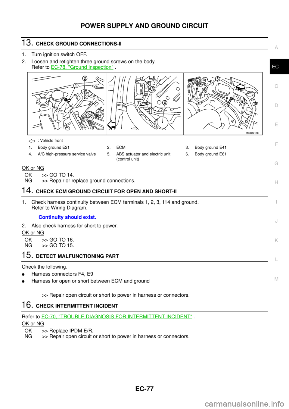
: Vehicle front
1. Body ground E21 2. ECM 3. Body ground E41
4. A/C high-pressure service valve 5. ABS actuator and electric unit
(control unit)6. Body ground E61
MBIB1218E
Continuity should exist.
Page 1057 of 3171

POWER SUPPLY AND GROUND CIRCUIT
EC-77
C
D
E
F
G
H
I
J
K
L
MA
EC
13.CHECK GROUND CONNECTIONS-II
1. Turn ignition switch OFF.
2. Loosen and retighten three ground screws on the body.
Refer toEC-78, "
Ground Inspection".
OK or NG
OK >> GO TO 14.
NG >> Repair or replace ground connections.
14.CHECK ECM GROUND CIRCUIT FOR OPEN AND SHORT-II
1. Check harness continuity between ECM terminals 1, 2, 3, 114 and ground.
Refer to Wiring Diagram.
2. Also check harness for short to power.
OK or NG
OK >> GO TO 16.
NG >> GO TO 15.
15.DETECT MALFUNCTIONING PART
Check the following.
lHarness connectors F4, E9
lHarness for open or short between ECM and ground
>> Repair open circuit or short to power in harness or connectors.
16.CHECK INTERMITTENT INCIDENT
Refer toEC-70, "
TROUBLE DIAGNOSIS FOR INTERMITTENT INCIDENT".
OK or NG
OK >> Replace IPDM E/R.
NG >> Repair open circuit or short to power in harness or connectors.
: Vehicle front
1. Body ground E21 2. ECM 3. Body ground E41
4. A/C high-pressure service valve 5. ABS actuator and electric unit
(control unit)6. Body ground E61
MBIB1218E
Continuity should exist.
Page 1059 of 3171

DTC U1000 CAN COMMUNICATION LINE
EC-79
C
D
E
F
G
H
I
J
K
L
MA
EC
DTC U1000 CAN COMMUNICATION LINEPFP:23710
DescriptionEBS01KDA
CAN (Controller Area Network) is a serial communication line for real time application. It is an on-vehicle mul-
tiplex communication line with high data communication speed and excellent error detection ability. Many elec-
tronic control units are equipped onto a vehicle, and each control unit shares information and links with other
control units during operation (not independent). In CAN communication, control units are connected with 2
communication lines (CAN H line, CAN L line) allowing a high rate of information transmission with less wiring.
Each control unit transmits/receives data but selectively reads required data only.
On Board Diagnosis LogicEBS01KDB
The MI will not light up for this self-diagnosis.
DTC Confirmation ProcedureEBS01KDC
NOTE:
If DTC Confirmation Procedure has been previously conducted, always turn ignition switch OFF and wait at
least 10 seconds before conducting the next test.
WITH CONSULT-II
1. Turn ignition switch ON and wait at least 3 seconds.
2. Select “DATA MONITOR” mode with CONSULT-II.
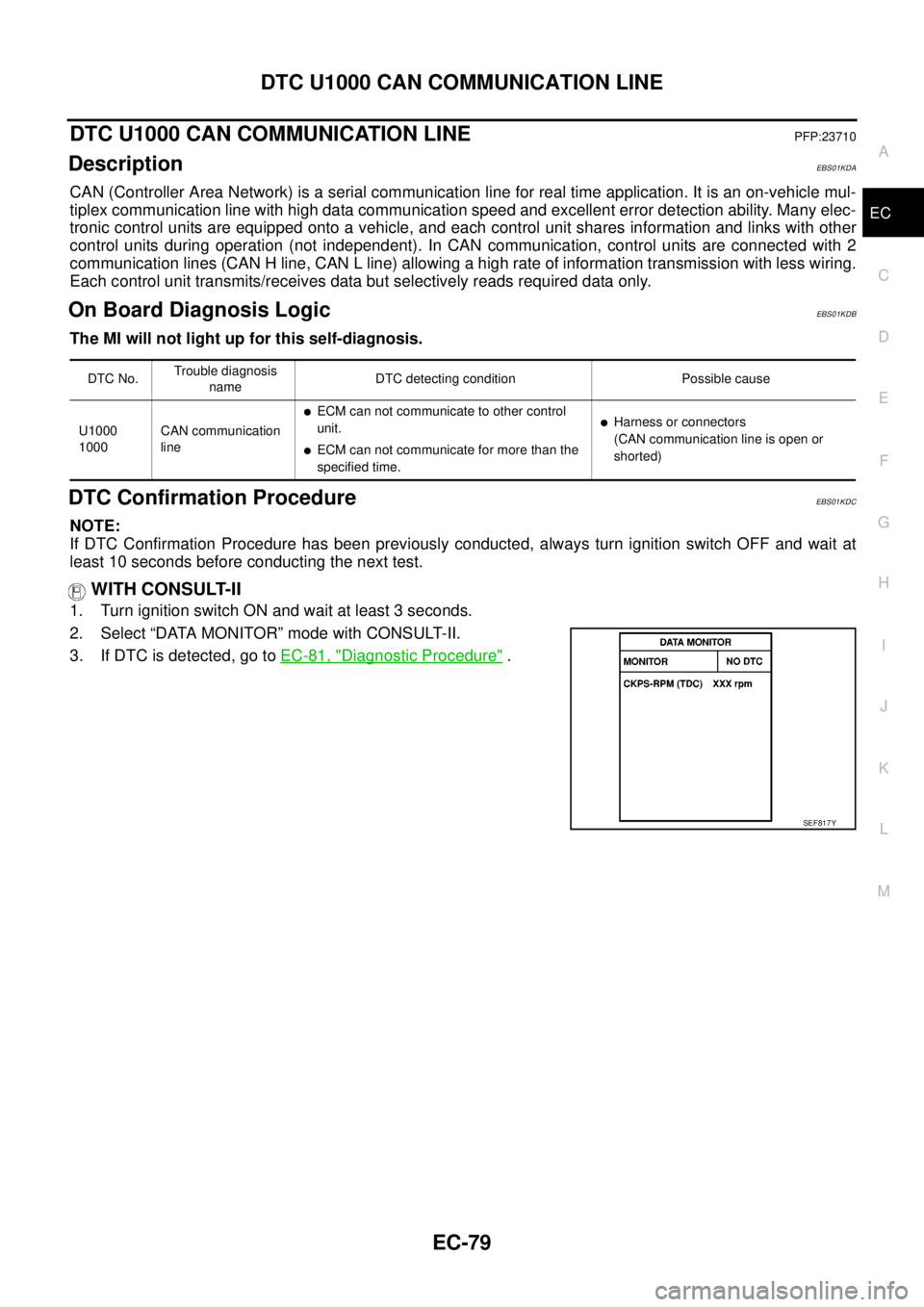
3. If DTC is detected, go toEC-81, "
Diagnostic Procedure".
DTC No.Trouble diagnosis
nameDTC detecting condition Possible cause
U1000
1000CAN communication
line
lECM can not communicate to other control
unit.
lECM can not communicate for more than the
specified time.
lHarness or connectors
(CAN communication line is open or
shorted)
SEF817Y
Page 1075 of 3171
DTC P0102, P0103 MAF SENSOR
EC-95
C
D
E
F
G
H
I
J
K
L
MA
EC
Diagnostic ProcedureEBS01KE1
1.CHECK GROUND CONNECTIONS
1. Turn ignition switch OFF.
2. Loosen and retighten three ground screws on the body.
Refer toEC-78, "
Ground Inspection".
OK or NG
OK >> GO TO 2.
NG >> Repair or replace ground connections.
2.CHECK MAFS POWER SUPPLY CIRCUIT
1. Disconnect mass air flow (MAF) sensor (1) harness connector.
–: Vehicle front
2. Turn ignition switch ON.
3. Check voltage between MAF sensor terminal 5 and ground with
CONSULT-II or tester.
OK or NG
OK >> GO TO 4.
NG >> GO TO 3.
: Vehicle front
1. Body ground E21 2. ECM 3. Body ground E41
4. A/C high-pressure service valve 5. ABS actuator and electric unit
(control unit)6. Body ground E61
MBIB1218E
MBIB1200E
Voltage: Battery voltage
PBIB1597E
Page 1081 of 3171
DTC P0112, P0113 IAT SENSOR
EC-101
C
D
E
F
G
H
I
J
K
L
MA
EC
Diagnostic ProcedureEBS01KE8
1.CHECK GROUND CONNECTIONS
1. Turn ignition switch OFF.
2. Loosen and retighten three ground screws on the body.
Refer toEC-78, "
Ground Inspection".
OK or NG
OK >> GO TO 2.
NG >> Repair or replace ground connections.
2.CHECK INTAKE AIR TEMPERATURE SENSOR POWER SUPPLY CIRCUIT
1. Disconnect mass air flow sensor (intake air temperature sensor
is built-into) (1) harness connector.
–: Vehicle front
2. Turn ignition switch ON.
3. Check voltage between MAF sensor terminal 2 and ground with
CONSULT-II or tester.
OK or NG
OK >> GO TO 3.
NG >> Repair harness or connectors.
: Vehicle front
1. Body ground E21 2. ECM 3. Body ground E41
4. A/C high-pressure service valve 5. ABS actuator and electric unit
(control unit)6. Body ground E61
MBIB1218E
MBIB1200E
Voltage: Approximately 5.3V
PBIB2176E
Page 1086 of 3171
EC-106
DTC P0117, P0118 ECT SENSOR
Diagnostic Procedure
EBS01KEF
1.CHECK GROUND CONNECTIONS
1. Turn ignition switch OFF.
2. Loosen and retighten three ground screws on the body.
Refer toEC-78, "
Ground Inspection".
OK or NG
OK >> GO TO 2.
NG >> Repair or replace ground connections.
2.CHECK ECT SENSOR POWER SUPPLY CIRCUIT
1. Disconnect engine coolant temperature sensor (1) harness con-
nector.
–: Vehicle front
–EGR volume control valve (2)
2. Turn ignition switch ON.
3. Check voltage between ECT sensor terminal 1 and ground with
CONSULT-II or tester.
OK or NG
OK >> GO TO 3.
NG >> Repair harness or connectors.
: Vehicle front
1. Body ground E21 2. ECM 3. Body ground E41
4. A/C high-pressure service valve 5. ABS actuator and electric unit
(control unit)6. Body ground E61
MBIB1218E
MBIB1230E
Voltage: Approximately 5.3V
SEF193Z
Page 1091 of 3171
DTC P0122, P0123 APP SENSOR
EC-111
C
D
E
F
G
H
I
J
K
L
MA
EC
Diagnostic ProcedureEBS01KEO
1.CHECK GROUND CONNECTIONS
1. Turn ignition switch OFF.
2. Loosen and retighten three ground screws on the body.
Refer toEC-78, "
Ground Inspection".
OK or NG
OK >> GO TO 2.
NG >> Repair or replace ground connections.
2.CHECK APP SENSOR 1 POWER SUPPLY CIRCUIT
1. Disconnect accelerator pedal position (APP) sensor (1) harness
connector.
2. Turn ignition switch ON.
3. Check voltage between APP sensor terminal 2 and ground with
CONSULT-II or tester.
OK or NG
OK >> GO TO 3.
NG >> Repair open circuit or short to ground or short to power
in harness or connectors.
: Vehicle front
1. Body ground E21 2. ECM 3. Body ground E41
4. A/C high-pressure service valve 5. ABS actuator and electric unit
(control unit)6. Body ground E61
MBIB1218E
MBIB1201E
Voltage: Approximately 5.3V
PBIB2608E
Page 1096 of 3171
EC-116
DTC P0182, P0183 FUEL PUMP TEMPERATURE SENSOR
Diagnostic Procedure
EBS01KEX
1.CHECK GROUND CONNECTIONS
1. Turn ignition switch OFF.
2. Loosen and retighten three ground screws on the body.
Refer toEC-78, "
Ground Inspection".
OK or NG
OK >> GO TO 2.
NG >> Repair or replace ground connections.
2.CHECK FUEL PUMP TEMPERATURE SENSOR POWER SUPPLY CIRCUIT
1. Disconnect fuel pump temperature sensor (1) harness connec-
tor.
–Fuel pump (2)
2. Turn ignition switch ON.
3. Check voltage between fuel pump temperature sensor terminal
1 and ground with CONSULT-II or tester.
OK or NG
OK >> GO TO 3.
NG >> Repair harness or connectors.
: Vehicle front
1. Body ground E21 2. ECM 3. Body ground E41
4. A/C high-pressure service valve 5. ABS actuator and electric unit
(control unit)6. Body ground E61
MBIB1218E
MBIB1389E
Voltage: Approximately 5.3V
PBIB2651E