Page 930 of 3171

DI-20
COMBINATION METERS
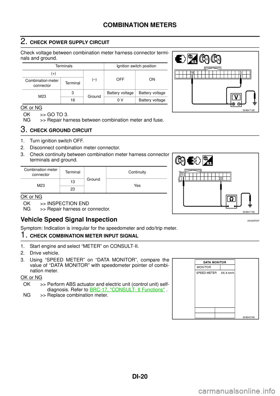
2.CHECK POWER SUPPLY CIRCUIT
Check voltage between combination meter harness connector termi-
nals and ground.
OK or NG
OK >> GO TO 3.
NG >> Repair harness between combination meter and fuse.
3.CHECK GROUND CIRCUIT
1. Turn ignition switch OFF.
2. Disconnect combination meter connector.
3. Check continuity between combination meter harness connector
terminals and ground.
OK or NG
OK >> INSPECTION END
NG >> Repair harness or connector.
Vehicle Speed Signal InspectionEKS00PDF
Symptom: Indication is irregular for the speedometer and odo/trip meter.
1.CHECK COMBINATION METER INPUT SIGNAL
1. Start engine and select “METER” on CONSULT-II.
2. Drive vehicle.
3. Using “SPEED METER” on “DATA MONITOR”, compare the
value of “DATA MONITOR” with speedometer pointer of combi-
nation meter.
OK or NG
OK >> Perform ABS actuator and electric unit (control unit) self-
diagnosis. Refer toBRC-17, "
CONSULT- II Functions".
NG >> Replace combination meter.
Terminals Ignition switch position
(+)
(–) OFF ON
Combination meter
connectorTerminal
M233
GroundBattery voltage Battery voltage
16 0 V Battery voltage
SKIB4718E
Combination meter
connectorTe r m i n a l
GroundContinuity
M2313
Ye s
23
SKIB4719E
SKIB4578E
Page 936 of 3171
DI-26
COMBINATION METERS
4.QUESTION 4
During driving, does the fuel gauge pointer move gradually toward EMPTY position?
YES >> Check the fuel level sensor unit. Refer toDI-27, "FUEL LEVEL SENSOR UNIT CHECK".
NO >> The float arm may interfere or bind with any of the components in the fuel tank.
DTC [U1000] CAN Communication CircuitEKS00L8X
Symptom: Displays “CAN COMM CIRC [U1000]” at the self-diagnosis result for combination meter.
1.CHECK CAN COMMUNICATION
1. Select “SELF-DIAG RESULTS” mode for “METER” with CONSULT-II.
2. Print out CONSULT-II screen.
>> Go to “LAN SYSTEM”. Refer toLAN-3, "
Precautions When Using CONSULT-II".
DTC [B2205] Vehicle Speed CircuitEKS00L8Y
Symptom: Displays “VEHICLE SPEED CIRC [B2205]” at the self-diagnosis result for combination meter.
Perform the ABS actuator and electric unit (control unit) self-diagnosis, and repair or replace malfunctioning
parts. Refer toBRC-17, "
CONSULT- II Functions".
Page 962 of 3171
DI-52
WARNING CHIME
SEAT BELT WARNING CHIME
Seat belt warning chime sound for approximately 90 seconds, when vehicle speed becomes more than 25 km/
h (16 MPH) with driver seat belt unfastened.
When driver seat belt is unfastened, ground is supplied as signal
lto combination meter terminal 24
lthrough seat belt buckle switch (driver side) terminals 1 and 2
lthrough grounds B9 and B25 (LHD models), B106 and B121 (RHD models).
ABS actuator and electric unit (control unit) provides a vehicle speed signal to the combination meter.
Combination meter detects that driver seat belt is unfastened (seat belt buckle switch ON) and vehicle speed
more than 25 km/h (16 MPH). And then it sounds seat belt warning chime for 90 seconds.
NOTE:
Warning chime should be turned off under the following conditions.
lDriver seat belt is fastened (seat belt buckle switch OFF)
l90 seconds elapsed since warning chime start
Component Parts and Harness Connector LocationEKS00L9C
PKIC2510E
Page 968 of 3171

DI-58
WARNING CHIME
CONSULT-II Function (BCM)
EKS00L9K
CONSULT-II can display each diagnostic item using the diagnostic test modes shown following.
DIAGNOSTIC ITEMS DESCRIPTION
CONSULT-II BASIC OPERATION PROCEDURE
CAUTION:
If CONSULT-II is used with no connection of CONSULT-II CONVERTER, malfunctions might be
detected in self-diagnosis depending on control unit which carry out CAN communication.
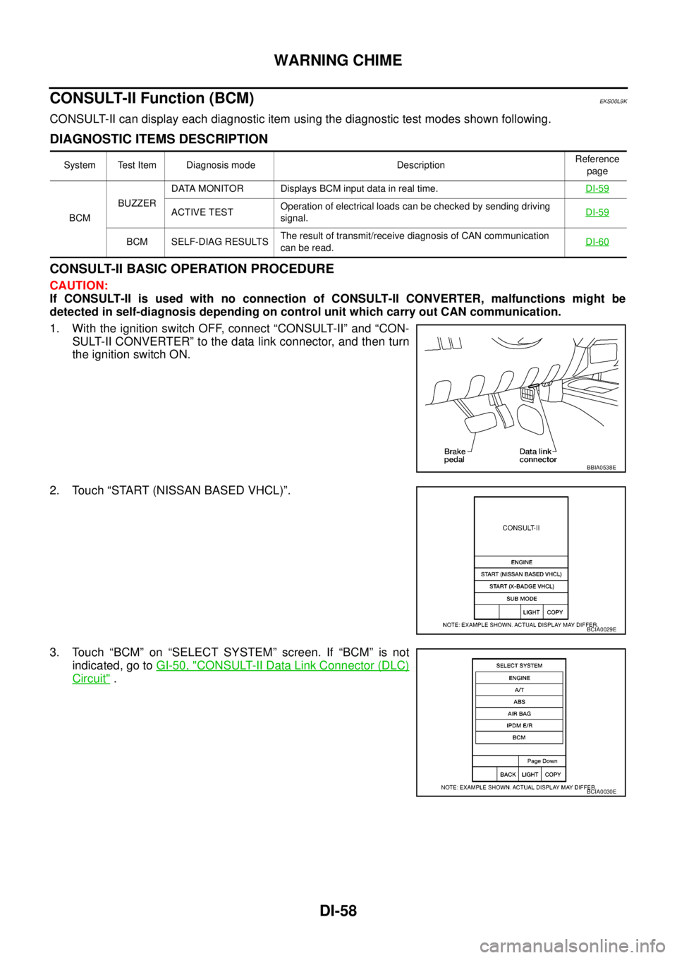
1. With the ignition switch OFF, connect “CONSULT-II” and “CON-
SULT-II CONVERTER” to the data link connector, and then turn
the ignition switch ON.
2. Touch “START (NISSAN BASED VHCL)”.
3. Touch “BCM” on “SELECT SYSTEM” screen. If “BCM” is not
indicated, go toGI-50, "
CONSULT-II Data Link Connector (DLC)
Circuit".
System Test Item Diagnosis mode DescriptionReference
page
BCMBUZZERDATA MONITOR Displays BCM input data in real time.DI-59
ACTIVE TESTOperation of electrical loads can be checked by sending driving
signal.DI-59
BCM SELF-DIAG RESULTSThe result of transmit/receive diagnosis of CAN communication
canberead.DI-60
BBIA0538E
BCIA0029E
BCIA0030E
Page 975 of 3171
CAN COMMUNICATION
DI-65
C
D
E
F
G
H
I
J
L
MA
B
DI
CAN COMMUNICATIONPFP:23710
System DescriptionEKS00MHE
CAN (Controller Area Network) is a serial communication line for real time application. It is an on-vehicle mul-
tiplex communication line with high data communication speed and excellent error detection ability. Many elec-
tronic control units are equipped onto a vehicle, and each control unit shares information and links with other
control units during operation (not independent). In CAN communication, control units are connected with 2
communication lines (CAN H line, CAN L line) allowing a high rate of information transmission with less wiring.
Each control unit transmits/receives data but selectively reads required data only.
CAN Communication UnitEKS00MHF
Refer toLAN-30, "CAN Communication Unit"in “LAN SYSTEM”.
Page 992 of 3171

EC-12
PRECAUTIONS
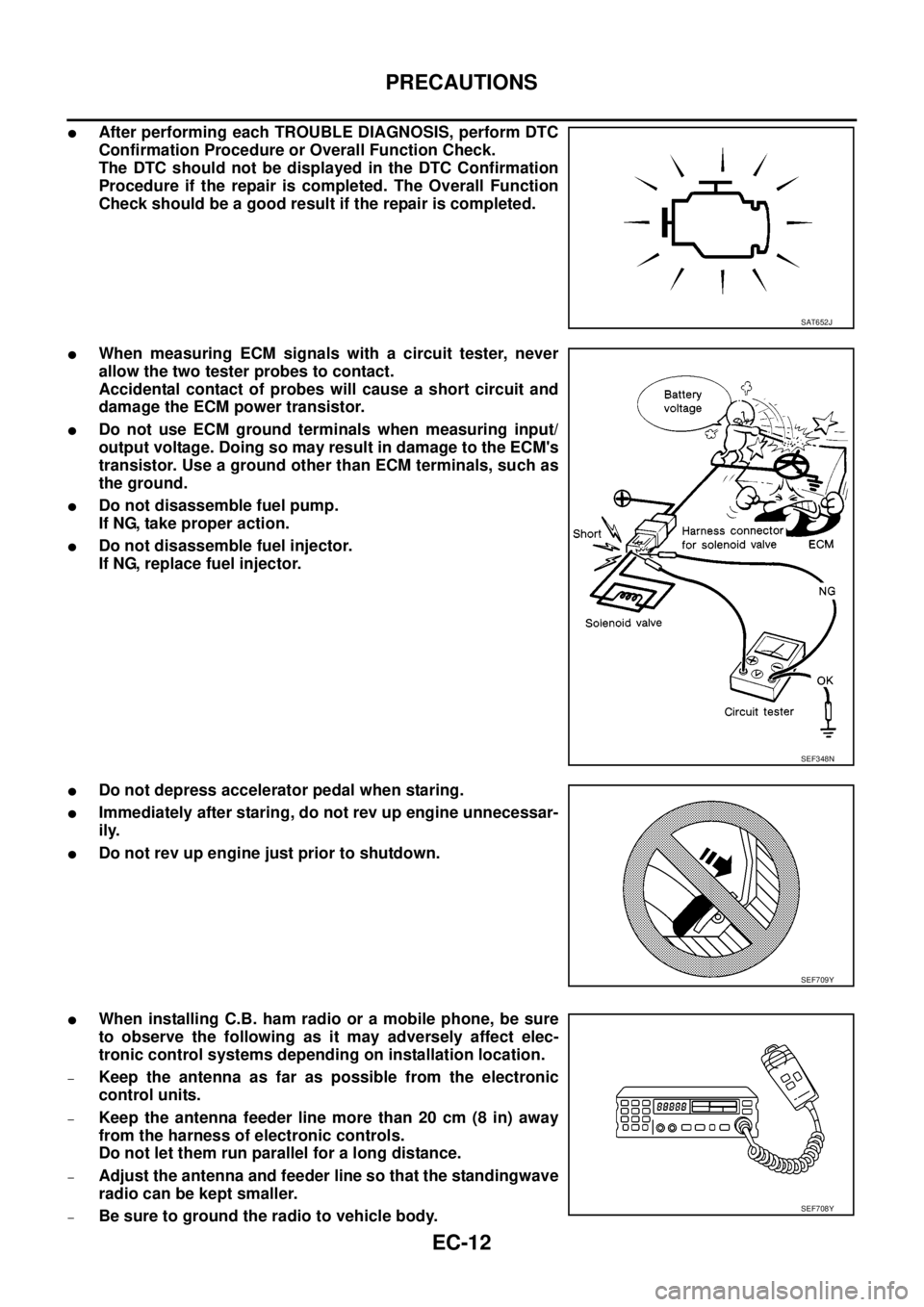
lAfter performing each TROUBLE DIAGNOSIS, perform DTC
Confirmation Procedure or Overall Function Check.
The DTC should not be displayed in the DTC Confirmation
Procedure if the repair is completed. The Overall Function
Check should be a good result if the repair is completed.
lWhen measuring ECM signals with a circuit tester, never
allow the two tester probes to contact.
Accidental contact of probes will cause a short circuit and
damage the ECM power transistor.
lDo not use ECM ground terminals when measuring input/
output voltage. Doing so may result in damage to the ECM's
transistor. Use a ground other than ECM terminals, such as
the ground.
lDo not disassemble fuel pump.
If NG, take proper action.
lDo not disassemble fuel injector.
If NG, replace fuel injector.
lDo not depress accelerator pedal when staring.
lImmediately after staring, do not rev up engine unnecessar-
ily.
lDo not rev up engine just prior to shutdown.
lWhen installing C.B. ham radio or a mobile phone, be sure
to observe the following as it may adversely affect elec-
tronic control systems depending on installation location.
–Keep the antenna as far as possible from the electronic
control units.
–Keep the antenna feeder line more than 20 cm (8 in) away
from the harness of electronic controls.
Do not let them run parallel for a long distance.
–Adjust the antenna and feeder line so that the standingwave
radio can be kept smaller.
–Be sure to ground the radio to vehicle body.
SAT652J
SEF348N
SEF709Y
SEF708Y
Page 1002 of 3171
EC-22
ENGINE CONTROL SYSTEM
CAN Communication
EBS01KCJ
SYSTEM DESCRIPTION
CAN (Controller Area Network) is a serial communication line for real time application. It is an on-vehicle mul-
tiplex communication line with high data communication speed and excellent error detection ability. Many elec-
tronic control units are equipped onto a vehicle, and each control unit shares information and links with other
control units during operation (not independent). In CAN communication, control units are connected with 2
communication lines (CAN H line, CAN L line) allowing a high rate of information transmission with less wiring.
Each control unit transmits/receives data but selectively reads required data only.
Refer toLAN-30, "
CAN Communication Unit", about CAN communication for detail.
Page 1041 of 3171
TROUBLE DIAGNOSIS
EC-61
C
D
E
F
G
H
I
J
K
L
MA
EC
INSPECTION PROCEDURE
CAUTION:
If CONSULT-II is used with no connection of CONSULT-II CONVERTER, malfunctions might be
detected in self-diagnosis depending on control unit which carry out CAN communication.
1. Turn ignition switch OFF.
2. Connect CONSULT-II and CONSULT-II CONVERTER to data
link connector, which is located under LH dash panel near the
hood opener handle.
3. Turn ignition switch ON.
4. Touch “START (NISSAN BASED VHCL)”.
5. Touch “ENGINE”.
If “ENGINE” is not indicated, go toGI-50, "
CONSULT-II Data
Link Connector (DLC) Circuit".
6. Perform each diagnostic test mode according to each service
procedure.
For further information, see the CONSULT-II Operation Manual.
BBIA0538E
BCIA0029E
BCIA0030E
BCIA0031E